
Subscribe to Our Youtube Channel
Related Manuals for Campbell CS475


Summary of Contents for Campbell CS475
- Page 1 CS475, CS476 and C477 Radar Water Level Sensor Revision: 1/10 C o p y r i g h t © 2 0 0 9 - 2 0 1 0 C a m p b e l l S c i e n t i f i c ,...
- Page 2 Warranty and Assistance The CS475, CS476, and CS477 RADAR WATER LEVEL SENSOR is warranted by CAMPBELL SCIENTIFIC, INC. to be free from defects in materials and workmanship under normal use and service for twelve (12) months from date of shipment unless specified otherwise. Batteries have no warranty.
-
Page 3: Table Of Contents
CS475, CS476, CS477 Table of Contents PDF viewers note: These page numbers refer to the printed version of this document. Use the Adobe Acrobat® bookmarks tab for links to specific sections. 1. Overview...............1 2. Specifications ..............2 3. Installation..............4 3.1 General Safety Instructions...............4 3.2 Unpacking Equipment ................4... - Page 4 List of Tables 3-1. Description of Components and Hardware Labels ......... 5 3-2. Radiation Beam Spread for CS475 (10° Beam Angle)......7 3-3. Radiation Beam Spread for CS476/CS477 (8° Beam Angle)....7 3-4. Description of Polarization Markings Labels ......... 8 4-1.
-
Page 5: Overview
Three sensor models are available that differ in their measurement range and accuracy. The CS475 can measure distances up to 65 feet with an accuracy of ±0.2 inches; the CS476 can measure up to 98 feet with an accuracy of ±0.1 inches;... -
Page 6: Specifications
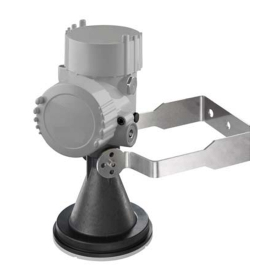
CS475, CS476, and CS477 Radar Water Level Sensor FIGURE 1-1. CS475, CS476, and CS477 2. Specifications Measurement Range CS475: 2 inch to 65 ft (50 mm to 20 m) CS476: 2 inch to 98 ft (50 mm to 30 m) - Page 7 CS475, CS476, and CS477 Radar Water Level Sensor Radar Unit Frequency: ~26 GHz Electromagnetic Compatibility: Emission to EN 61326; Electrical Equipment Class B Pulse Energy: 1 mW maximum Beam angle CS475: 10° (3-in dia horn) CS476, CS477: 8° (4-in dia horn)
-
Page 8: Installation
CS475, CS476, and CS477 Radar Water Level Sensor 3. Installation 3.1 General Safety Instructions Observe standard regulations and guidelines while installing and operating the radar sensors. You should follow country-specific installation standards, prevailing safety regulations, accident prevention rules, and this manual’s safety instructions. -
Page 9: Components And Hardware
CS475, CS476, and CS477 Radar Water Level Sensor FIGURE 3-1. Components and Hardware (see Table 3-1 for description of labels) TABLE 3-1. Description of Components and Hardware Labels CS475 CS476 or CS477 Optional Mounting Base Optional Protective Shield Mounting Loop... -
Page 10: Installation Recommendations
Obstructions to be aware of include excessive waves, splashing, pipes, wires, and logs. Note that the radiation beam spreads as it leaves the sensor (see Tables 3-2 and 3-3). NOTE Usually the beam path is 10° for the CS475, and 8° for the CS476/CS477. -
Page 11: Sensor Mounting
CS475, CS476, and CS477 Radar Water Level Sensor TABLE 3-2. Radiation Beam Spread for CS475 (10° Beam Angle) Distance in Diameter of Footprint in Meters Meters 0.18 0.87 1.76 2.64 3.53 TABLE 3-3. Radiation Beam Spread for CS476/CS477 (8° Beam Angle) -
Page 12: Instrument Housing Adjustment
CS475, CS476, and CS477 Radar Water Level Sensor hex nut indicate which direction the lobes extend the least. Orient the sensor such that one of the marks is aligned towards the wall or pier (see Figure 3-2 and Table 3-4). -
Page 13: Wiring
CS475, CS476, and CS477 Radar Water Level Sensor 4. Wiring 4.1 Datalogger Connection As shipped from Campbell Scientific, the sensor is fitted with a cable for connection with the datalogger. Appendix A describes replacing this cable. Connections to Campbell Scientific dataloggers are given in Table 4-1. When Short Cut is used to create the datalogger program, the sensor should be wired to the channels shown on the wiring diagram created by Short Cut. -
Page 14: Configuration
CS475, CS476, and CS477 Radar Water Level Sensor 5. Configuration 5.1 Default Settings In most circumstances, the default settings (see Table 5-1) should be used. Refer to Appendix B for other setting options and SDI-12 commands. TABLE 5-1. Default Settings... -
Page 15: Set Water Stage
CS475, CS476, and CS477 Radar Water Level Sensor radar sensor then emits the short microwave pulses. Any echo occurring 0.5 m (1.6 ft) short of the distance you entered will be considered noise. To start false echo learn, do the aXSFEL+nnn.nnn! command (where nnn.nnn = the actual distance to the water) followed by the aD0! (Send Data) command. -
Page 16: Programming
6. Programming This section is for users who write their own datalogger programs. A datalogger program to measure this sensor can be created using Campbell Scientific’s Short Cut Program Builder software. You do not need to read this section to use Short Cut. -
Page 17: Example Program
CS475, CS476, and CS477 Radar Water Level Sensor The SDI12Recorder instruction has the following parameters: Dest The Dest parameter is a variable in which to store the results of the measurement. Dest must have enough elements to store all the data that is returned by the sensor or a 'variable out of range' error will result during the execution of the instruction. -
Page 18: Edlog
CS475, CS476, and CS477 Radar Water Level Sensor ‘Define a data table for 60 minute maximum and minimums DataTable (Hourly,True,-1) DataInterval(0,60,Min,10) Maximum(1,Distance,FP2,0,0) Minimum(1,Distance,FP2,0,0) Average(1,Distance,FP2,False) StdDev(1,Distance,FP2,False) Maximum(1,Stage,FP2,0,0) Minimum(1,Stage,FP2,0,0) Average(1,Stage,FP2,False) StdDev(1,Stage,FPs,False) Sample (1,Error_Code,UINT2) EndTable ‘Read sensor every 60 seconds BeginProg Scan(60,sec,1,0) ‘Code for SDI-12 measurements: SDI12Recorder(CS475,1,0,”M!”,1,0) -
Page 19: Example Program
CS475, CS476, and CS477 Radar Water Level Sensor NOTE Edlog allocates only one of the input locations needed for this instruction. Three input locations are required for this sensor. The additional input locations must be inserted manually using the Input Location Editor. For information on manually inserting input locations, refer to Manually Inserting Input Locations in the Edlog help. -
Page 20: Diagnostics, Repair, And Maintenance
CS475, CS476, and CS477 Radar Water Level Sensor 7. Diagnostics, Repair, and Maintenance 7.1 Testing Procedure The test procedures for the sensor require the following steps: 1. Double check all wiring connections. 2. Connect the sensor to your datalogger and apply +12V power. -
Page 21: Check Unit Response
CS475, CS476, and CS477 Radar Water Level Sensor • Distance--the distance between the sensor and water surface. This value will be reported in either meters or feet, depending on the Units setting. • Diagnostic Values—an error code. For example, Code 0 = OK, Code 13 = error E013 (see Section 7.2). -
Page 22: Cyclic Redundancy Check (Crc)
CS475, CS476, and CS477 Radar Water Level Sensor • Manufacturer’s Model Number: PS61 (CS475), PS62 (CS476), or PS63 (CS477) • Three Digit Firmware Version Number. • Eight Digit Serial Number of Sensor. TABLE 7-3. Send Identification Command Initial Command Response a13VEGAbbbbPS6233212345678<cr><If>... -
Page 23: Get Units
CS475, CS476, and CS477 Radar Water Level Sensor Table 7-4 shows an example of checking the CRC. TABLE 7-4. Checking CRC Example Initial Command Response 00013<cr><If> where 0=the sensor’s address Where (from left to right), 0—sensor’s address; 001—the amount of time (in seconds) that you must wait before sending the send data command;... -
Page 24: Diagnostics And Repair
• Exchange the electronics module (see Section 7.2.2.1) • Return the equipment for repair (an RMA is required) 7.2.2.1 Exchange Electronics Module If you do not have an electronics module onsite, order one from Campbell Scientific. - Page 25 CS475, CS476, and CS477 Radar Water Level Sensor The electronics module is replaced by doing the following steps (see Figure 7- 1 and Table 7-5): 1. Unscrew the housing cap (cap is not shown in Figure 7-1). 2. Remove all wires that are attached or plugged into the electronics and note their location for reassembly.
-
Page 26: Description Of Changing The Electronics Labels
CS475, CS476, and CS477 Radar Water Level Sensor FIGURE 7-1. Changing the Electronics (see Table 7-5 for label descriptions) TABLE 7-5. Description of Changing the Electronics Labels Description Red Wire Housing Top View Screws to Secure Electronics to Housing Electronics... -
Page 27: Maintenance
CS475, CS476, and CS477 Radar Water Level Sensor 7.3 Maintenance The sensors are maintenance free under normal operation. - Page 28 CS475, CS476, and CS477 Radar Water Level Sensor...
- Page 29 Appendix A. Replacing the Cable The sensor is fitted with a cable for connection to the dataogger. The following procedure is for replacing the original cable (see Figure A-1 and Table A-1). 1. Unscrew the housing side compartment screw cap. 2.
-
Page 30: A-1. Description Of Instrument Housing Labels
Appendix A. Replacing the Cable FIGURE A-1. Connecting the Instrument Housing (see Table A-1 for description of labels) TABLE A-1. Description of Instrument Housing Labels Connections Description Side Chamber SDI-12 Wiring Top Chamber Inner Housing Connections Typical SDI-12 Network Configuration DIS61 (Optional) (Reference V-2799S0) Inner Housing Connections (Modular Plug Mounted in Dual Chamber Housing), Plugs into Back of SDI-12 Board... - Page 31 Appendix B. Entering SDI-12 Commands/Changing Settings The SDI-12 commands are entered using the 25616 Adjustment/Display Module or the terminal emulator in LoggerNet or PC400. These commands are also used in CRBasic or Edlog programming (see Section 6). During normal communication, the datalogger sends the address, together with a command, to the sensor.
-
Page 32: B-1. Sdi-12 Commands
Appendix B. Entering SDI-12 Commands/Changing Settings TABLE B-1. SDI-12 Commands Function SDI-12 Command Address Query Send Identification Acknowledge Active Change Address aAb! Where a is the current address and b is the new address Start Verification Start Measurement Start Measurement and aMC! Request CRC Send Data... -
Page 33: Changing Settings
Appendix B. Entering SDI-12 Commands/Changing Settings B.1 Changing Settings B.1.1 Query/Set the Address Valid addresses are 0 to 9; A through Z; and a through z. The factory default address is set to 0. The address can be verified by sending the sensor the Address Query command (see Table B-2). -
Page 34: Set Water Conditions
Appendix B. Entering SDI-12 Commands/Changing Settings B.1.3 Set Water Conditions The Set Water Conditions command adapts the sensor to different water conditions. There are four different settings: • 0 (custom setting) • 1 (smooth--typical peak to trough of wave < 4”) •... -
Page 35: B-6. Example For Setting Power Operation Mode
Appendix B. Entering SDI-12 Commands/Changing Settings • 0 (OFF—this mode is typically not recommended; sensor is completely off until a new set power command is received) CAUTION The OFF power mode should only be used by advanced users who want to turn the sensor off for extended time periods. In this mode the sensor is completely off and only responds to a new set power command. - Page 36 Appendix B. Entering SDI-12 Commands/Changing Settings...
- Page 37 Appendix C. FCC/IC Equipment Authorization (USA/Canada only) The CS475, CS476, and CS477 are FCC approved. Modifications to the sensors must have express agreement from Campbell Scientific. Any modifications not approved by Campbell Scientific will cause the expiration of the operating license issued by the FCC/IC. The radar sensor is in conformity with Part 15 of the FCC directives and fulfills the RSS-210 regulations.
- Page 40 Campbell Scientific Companies Campbell Scientific, Inc. (CSI) 815 West 1800 North Logan, Utah 84321 UNITED STATES www.campbellsci.com • info@campbellsci.com Campbell Scientific Africa Pty. Ltd. (CSAf) PO Box 2450 Somerset West 7129 SOUTH AFRICA www.csafrica.co.za • cleroux@csafrica.co.za Campbell Scientific Australia Pty. Ltd. (CSA)
Need help?
Do you have a question about the CS475 and is the answer not in the manual?
Questions and answers