Table of Contents
Advertisement
Quick Links
Advertisement
Table of Contents

Subscribe to Our Youtube Channel
Related Manuals for Fermax MEET KIN 1445


Summary of Contents for Fermax MEET KIN 1445
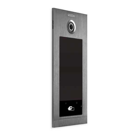
- Page 1 REF. 1445 KIN PANEL INSTALLER MANUAL INSTALLER MANUAL...
- Page 2 Technical publication for information purposes edited by FERMAX ELECTRÓNICA S.A.U. FERMAX ELECTRÓNICA applies a continuous improvement policy, therefore it reserves the right to modify the contents of this document, as well as the product features hereof at any time and without prior notice. Any modification will be reflected in subsequent editions of this document.
-
Page 3: Table Of Contents
INDEX 1 DESCRIPTION ..........................4 2 WEB BROWSER PROGRAMMING ....................5 2.1 DEVICE .............................. 6 2.2 GENERAL ............................7 2.3 NETWORK CONFIGURATION ......................10 2.4 ACCESS ............................11 2.5 FACE RECOGNITION........................13 2.6 IP CAMERA............................14 2.7 SIP ..............................15 2.8 SIP TRUNK ............................ -
Page 4: Description
Residents can access to their corresponding entrance by passing their authorized Mifare identifier. The door will open and release the lock. The Mifare identifier data must be added through FERMAX MEET MANAGEMENT software. Maximum 100.000 identifiers. By means of their WIEGAND connection (output) it is possible to integrate this Mifare reader in third party Access Control Systems. -
Page 5: Web Browser Programming
2 WEB BROWSER PROGRAMMING For programming of the KIN panel, access is required through a PC via a web browser. Preferably use Chrome browser. The PC must be connected to the same LAN as the panel and configured with an IP address in the same range. -
Page 6: Device
2.1 DEVICE The section DEVICE provides technical information regarding the equipment, as a reference. FERMAX KIN PANEL: Device type FIRMWARE: Version of the installed firmware DEVICE: Type and panel number MAC: Panel MAC number IP: IP address assigned to the panel... -
Page 7: General
2.2 GENERAL The section GENERAL allows the configuration of the identification parameters of the KIN panel within the installation. It allows time-date configuration. Button for saving options above of it Button for saving date/time options only. TYPE: Select the identification parameters of the panel. There are some other parameters related, depending on TYPE selection: GENERAL ENTRANCE PANEL Panel installed in one of the main entrances to a condominium... - Page 8 In the case of ALPHANUMERIC call, the available characters are A to H. The panel will convert character A to 1, B to 2, etc. For example, dialling 80C, the called is 803. BLOCK PANEL ENTRANCE Panel installed in a single building or in a block of a condominium •...
- Page 9 LANGUAGE: Select the desired language in the dropdown options. Default option is ENGLISH. Refresh the webpage after changing the language PANEL VOLUME: Select the desired value between 1 and 5. Default option is 4 The conversation volume is common for uplink and downlink. ...
-
Page 10: Network Configuration
If the installation has no FERMAX MANAGEMENT SOFTWARE the installer can set date, time and time zone manually. Do not use the GMT (TIME ZONE) adjustment in this case. GMT is usable only when the time is automatically taken from internet or FERMAX MANAGEMENT SOFTWARE. -
Page 11: Access
SOFTWARE PIN: PIN ACCESS code for the Management Software control. The default setting is 123456. Indicate the corresponding parameters and click SAVE to confirm. NOTE: The MEET system uses static IP addressing. This ensures that each device has a unique IP address in the same installation. - Page 12 If there are not more cards to program, after two minutes the panel will exit program mode. There is not possible to deregister cards programmed by this method. Use the FERMAX MEET MANAGEMENT SOFTWARE for full operational possibilities.
-
Page 13: Face Recognition
2.5 FACE RECOGNITION Use this setting to enable or disable the FACE RECONGNITION function of the panel. The FERMAX MANAGEMENT SOFTVARE V01.05 is required for programming and managing the photos of the authorized faces. System supports up to 6.000 faces ... -
Page 14: Ip Camera
2.6 IP CAMERA The monitor can switch to IP CCTV camera video during a conversation. This function allows to configure IP CCTV cameras using RTSP protocol to be displayed as an auxiliary camera to provide different view angles from the door or related areas ... -
Page 15: Sip
This option allows to configure KIN panel to use SIP functionalities, such us smartphone divert using the FERMAX MEET ME APP or allows the panel to operate with a third party SIP systems or terminals using SIP protocol instead of FERMAX MEET protocol. - Page 16 Configuration for SIP server integration Configure the SIP parameters as explained below, for the cases where the KIN panel works as an extension of a SIP server. Contact with the SIP server administrator to get some of the information required in this section. ...
-
Page 17: Sip Trunk
2.8 SIP TRUNK When there is a VoIP gateway installed on the network connected to a PSTN line or cloud SIP TRUNK SERVER. The panel call can be diverted to user's mobile phone or land line telephone through a voice gateway. ENABLE SIP TRUNK: Enable or disable SIP trunk function. -
Page 18: Sip Call
This option allows to generate calls to smartphone devices in the cases where it is not a MEET monitor associated in the installation. A FERMAX MEET ME licence Ref. 1496 is required for each apartment The call can be received, simultaneously, in 8 smartphones in the same apartment. - Page 19 • Apartment 170 generates a call to the monitor IP 192.168.1.190 in the same installation. • Apartment 171 generates a call to the smartphone with FERMAX MEET ME licence 0103283. • Apartment 645 generates a call to the monitor IP 192.168.1.195 in the same installation.
-
Page 20: Advanced
IP 192.168.1.195 in the installation. • Apartment 183 generates a call to the SIP device 1234 of the SIP server with IP 192.168.1.170 and to the monitor IP 192.168.1.197 in the installation and to the smartphone with FERMAX MEET ME licence 0103283. - Page 21 Use Microsoft Excel to open the created file. It will have a look like that The first cell (A1) has the content: APARTMENT, NAME, Do not change it. Use the following cells (A2, A3, A4, etc.) to fill in the data of apartment name ad user’s name, with the format “Apartment number”, “Name”, Once the table has been finished, save it and import to the panel.
- Page 22 EXAMPLE NOTE: In the case of non-Latin alphabets (for example: Chinese, Russian / Cyrillic, Arabic, Hebrew etc.), the procedure is as follows: 1. From the web server of the panel, export the empty .CSV file. 2. Open with Windows Notepad and copy the directory list of the CSV file in the notepad with the desired alphabet (Latin, Chinese, Russian / Cyrillic, Arabic, ...).
-
Page 23: Pincode
Make a note of the new PIN at your convenience. If you lose or forget your PIN, you should contact FERMAX's Technical Department to receive instructions regarding its recovery. All settings programmed into the monitor will be lost after recovery. -
Page 24: Restore
2.13 RESTORE Use this functionality to remotely reset the KIN panel, or to return it to factory settings. In both cases it will ask for confirmation. RESTORE FACTORY SETTINGS: The panel will automatically turn off and start up with the factory settings. -
Page 25: Log Out
2.14 LOG OUT Use this functionality if you want to end your working session with this panel The panel will request access credentials again in the case of new access via web server... -
Page 26: Operation
3 OPERATION The screen of the KIN PANEL is interactive, so its performance depends on the call process or selected function. When someone stands in front of the panel or touches anywhere in the screen, a standby interface is shown. This standby interface can be a keypad for calling or HELP information, depending on the programming settings. - Page 27 ALPHANUMERICAL KEYPAD It is possible to call the apartments using letters and numbers. To call an apartment, dial apartment number and/or letters and press the telephone icon. Then follow instructions on screen. Available letters are A to H. The panel converts these letters to numbers: A to 1, B to 2, etc. For example, dialling 80C, the called monitor is 803.
- Page 28 ON SCREEN INFORMATION It is possible to get basic information on the equipment configuration through the screen 1. Dial 9999, The screen will display information followed by the telephone about panel settings: icon. • Firmware version • General settings • Serial number •...
-
Page 29: Icon Functions
3.1 Icon functions Depending on the programming and capabilities of the installation, some icon functions will available on the bottom of the screen. Up to 5 icons will appear on the screen. If there are more than 5 functions available, use the horizontal scroll over the icons to make visible the hidden ones. - Page 30 Users should stay for a few seconds in front of the panel. If the user´s face has been programmed and the system recognises him, the door will open. NOTE: Face recognition requires previous programming by means of the FERMAX MEET MANAGEMENT Software. DIRECTORY icon...
- Page 31 It allows to use a directory for selecting and calling an apartment searching the owner´s name. It is possible to make a scroll in the list or select the letter of the right side to filter the names which their first letter matches. A programming is required.
- Page 32 ACCESS PIN icon This option allows users open the door by means of entering an ACCESS PIN code. Length of ACCESS PIN could be between 4 to 6 digits. The panel admits up to 8 different ACCESS PIN, that must be programmed by the installer. See WEB BROWSER PROGRAMMING section for further details.
-
Page 33: Installation
4 INSTALLATION 4.1 Flush box installation 4.2 Installation Guide Diagram Base flush box depth The upper part of the Flush box install. adjustment hook. panel is stuck in, then move the panel to the flush box. Move the slider of the panel and fix the two screws. -
Page 34: Connectors
4.3 Connectors The KIN panel is connected to the installation by means of connectors: Ethernet for LAN connection and MOLEX type connectors for other connections (power supply, RS-485, etc.). A bag containing the corresponding female connectors with their cables comes with the panel. POWER INPUT: 12 Vdc power supply for the cases where no LAN PoE is available. -
Page 35: Basic Diagrams
The panel has an internal tamper button. If the panel is separated from the wall, an alarm is triggered in the panel, concierge and FERMAX MANAGENEMN SYSTEM (if exists). 4.4 Basic diagrams Basic diagram using PoE Switch. Use a power supply adapted electric lock voltage &... -
Page 36: Diagram Installation Of The Guest Code Module Ref. 1494
NOTE: The 1491 module need be connected to the PANEL No.1 in the block. The decoder RS485 address need be set to number 2 (factory defaults is 2). 4.6 Diagram installation of the GUEST CODE Module Ref. 1494 4.7 Diagram installation of the lift control system Ref. 9545 This installation has to be performed in the PANEL nº... -
Page 37: Technical Specifications
5 TECHNICAL SPECIFICATIONS Power supply: 12 Vdc or PoE (*) Standby current: 250 mA. With heating resistance ON: 750mA (**) Working current: 1000 mA. With heating resistance ON: 1500mA (**) (*) In cold places below -20ºC use a 12 Vdc 2A power supply instead of PoE. (**) An internal heating resistor is connected automatically when temperature is below -20ºC •... -
Page 38: Annex
FERMAX's Technical Department periodically informs (through Communications, Technical Bulletins, etc.) about the release of a new firmware update, as well as the improvements incorporated. Contact the FERMAX Technical Department if you wish to receive the corresponding update file. The firmware update is performed via the The procedure for updating the firmware with the corresponding update file is as follows. -
Page 39: Regulations
6.2 Regulations RADIO FREQUENCY MODULE. EC DECLARATION OF CONFORMITY: FERMAX ELECTRÓNICA, S.A.U. declares that this product complies with the requirements in the RED 2014/53/EU Directive “Radio frequency equipment”. https://www.fermax.com/intl/en/pro/documents/technical-documentation/DT-13-declarations-of- conformity.html Radio frequency module: • Frequency: / Maximum Power: 2,45mW. 13.56MHz This device, pursuant to Part 15 of the FCC Rules.
Need help?
Do you have a question about the MEET KIN 1445 and is the answer not in the manual?
Questions and answers