
Subscribe to Our Youtube Channel
Related Manuals for Fermax MEET 1W


Summary of Contents for Fermax MEET 1W
- Page 1 MEET 1W Panel INSTALLER'S MANUAL ENGLISH Version Cod. 970137Ic V11_19 This manual corresponds to MEET 1W Panel version V10.202...
- Page 2 FERMAX ELECTRÓNICA S.A.U. http://www.fermax.com MEET 1W Panel manual available at https://www.fermax.com/qr/meet/ Copyright Notice Fermax and Fermax MEET panel are trademarks of Fermax Electronica S.A.U. registered in the European Union and other countries. © FERMAX ELECTRÓNICA S.A.U., 2018. Page 2...
-
Page 3: Table Of Contents
INDEX Product Introduction ....................... 4 Overview ........................ 4 Functions Introduction ....................5 Call Apartment ....................... 5 Mifare Reader (Only panel with proximity reader) ..........5 Configuration via Web Server ..................6 Device Information ....................6 General Settings ....................7 Network Settings ....................8 ACC ........................ -
Page 4: Product Introduction
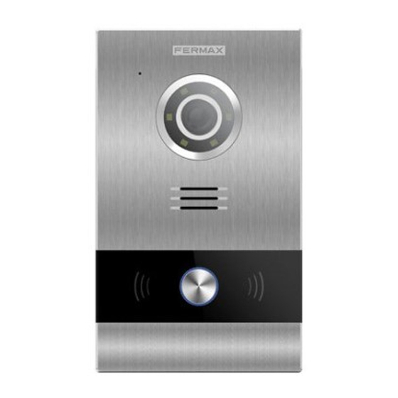
1 Product Introduction 1.1 Overview Microphone 1 Mpx High definition camera Lighting for night vision with LEDs Speaker Pushbutton for calling Mifare reader (Only for panel with Slider Page 4... -
Page 5: Functions Introduction
2 Functions Introduction Call apartment Open door, relay delay settings Connect exit button Speech message for release lock Door opened alarm Tamper alarm Alarm management by access control (only panel with proximity reader) 2.1 Call Apartment Visitor push the pushbutton for calling in the 1W Panel, the ring back tone will be sent, meanwhile the monitor will ring. -
Page 6: Configuration Via Web Server
3 Configuration via Web Server The 1W panel has an integrated web server, which allows to configure the parameters. This web server is accessed via the panel’s IP address. The browser opens with the configured IP address of the panel. A screen opens requesting a username and password. -
Page 7: General Settings
3.2 General Settings BLOCK: Block number the 1W panel, between 001 and 999 (default option 1). APARTMENT: Apartment number communicates with 1W panel, between 0001 and 9899 (default option 101). DEVICE NO.: Panel Number, between 1 and 9 (default option 1). TYPE: 1W PANEL. -
Page 8: Network Settings
3.3 Network Settings MEET allows to the installer to define the IP range according to the project needs and make the network management easier. MEET panel network mode is static mode. Ensure that each device has a unique IP address in same installation. The devices (digital panel, monitor and guard unit) will show IP conflict if there same IP is used on the same LAN. -
Page 9: Acc
3.4 ACC DOOR RELAY TIME: Time that the lock-release relay remains active (1-9s optional). OPEN DOOR DELAY: Time delay between door lock command is sent, and door lock relay is activated. The delay time is useful when the lock is not close to the panel (0-9s optional). ADMIN CARD: Master card registered to enroll additional prox cards. -
Page 10: Sip Settings
3.5 SIP Settings ENABLE SIP: Enable or disable sip function. SIP SERVER: SIP server IP address. DOMAIN: Sip server domain. OUTBOUND: Some servers are used when NAT is active on the router. STUN IP: Audio and video NAT traversing public network server IP. STUN PORT: The port of audio and video NAT traversing public network server. -
Page 11: Advanced Settings
3.6 Advanced Settings Quick dial is associated a MIO monitor, guard unit or sip terminal. QUICK DIAL: Enable or disable quick dial function. NOTE: The panel type do not be used 1W panel if you enable quick dial. URL: if call device of MEET system, URL: sip: sip account @ IP address of MEET device, the sip account is optional. -
Page 12: Log Out
3.8 Log Out Log out the web server Page 12... -
Page 13: Installation
4 Installation 4.1 Installation height Page 13... -
Page 14: Installation Step Diagram
4.2 Installation Step Diagram ○ ○ ○ ,1Flush box install. ,2Base flush box depth adjustment hook. ,3The upper part of the panel is stuck in, then move the panel to the flush box. 1.7CM 1.7CM ○ ,4Move the slider of the panel and fix the two screws, when installing, pay attention to the reservation of the 1.7CM space around the door to move the slide cover. -
Page 15: Connectors
4.3 Connectors 10/100Mbps RJ45 Port +12V,—: 12Vdc Power Input NC C,NO: Relay contacts for release lock EXIT,—: Exit button —, DS: Door-open sensor 485+, 485-: RS485 port Page 15... -
Page 16: Technical Parameters
Maximum number of per home: 9 Operating temperature: -20~70℃ Relative humidity: 20%~93%, without condensation RADIO FREQUENCY MODULE. EC DECLARATION OF CONFORMITY: FERMAX ELECTRÓNICA, S.A.U. declares that this product complies with the requirements in the RED 2014/53/EU Directive “Radio frequency equipment”. https://www.fermax.com/intl/en/pro/documents/technical-documentation/DT-13-declarations- of-conformity.html Radio frequency module: Frequency: 13.56MHz / Maximum Power:...
Need help?
Do you have a question about the MEET 1W and is the answer not in the manual?
Questions and answers