Advertisement
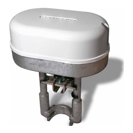
Globe Valves Actuators
with Emergency Fail Safe Function
Force
Model
Power supply
[N]
MVE206R
600
230Vac
MVE210R
1000
230Vac
MVE215R
1500
230Vac
MVE206SR
600
230Vac
MVE210SR
1000
230Vac
MVE215SR
1500
230Vac
APPLICATION AND USE
MVER is a flexible electro-mechanical actuator equipped with elec-
tronic fail safe function device for the control of two-way and three-
way globe valves in:
•
Heating and cooling systems;
•
Air Handling Units;
•
District heating plants;
•
Industrial temperature control systems.
The actuator is endowed with an electronic emergency return func-
tion which operates through the use of ultracapacitors whose life is
about 10 years if the actuator operates within the operation limits
declared in this data sheet.
The emergency position (retracted or extended stem) is set through
the use of a jumper which can be easily reached (look at paragraph
"DIP switches and jumper settings").
The actuator is supplied with totally discharged ultracapacitors and
at its first start a pre-charge phase of 130s max will be necessary.
N.B.: in this condition during the first 20-30s no LED signal on the ult-
racapacitors upper control board will be revealed; when this inter-
val has elapsed the RED LED will power on (ultracapacitors charging
phase, look at table on page 7).
During this phase all the functions of the actuator are inhibited and
the charge status of the ultracapacitors is signalled through 2 LEDs
(look at paragraph "Standard LEDs").
MVE.R can be controlled either by a proportional (modulating) sig-
nal or by an increase/decrease (floating) signal.
Controlli S.p.A.
16010 Sant'Olcese (GE)
Tel. 010 73 06 1
Fax. 010 73 06 870/871
www.controlli.eu
Description
long yoke, modulating/
floating control with position
emergency return with
totally open or closed valve
selectable through jumper
long yoke, modulating/
floating control with position
emergency return with
totally open or closed valve
selectable through jumper
long yoke, modulating/
floating control with position
emergency return with
totally open or closed valve
selectable through jumper
short yoke, modulating/
floating control with position
emergency return with
totally open or closed valve
selectable through jumper
short yoke, modulating/
floating control with position
emergency return with
totally open or closed valve
selectable through jumper
short yoke, modulating/
floating control with position
emergency return with
totally open or closed valve
selectable through jumper
1
Issue rev. b
st
It is easy to mount and connect the actuator. Direct mounting is pos-
sible to any CONTROLLI flanged valve. Linkage kits are available for
CONTROLLI threaded valves as well as for valves of other manufac-
turers. The actuator has a fine resolution (500 steps on the full stroke
range) for accurate fluid control and it is able to self-calibrate on a
different stroke without the need of any user action (this function is
DIP switch selectable on the field).
MVE.R has intelligent behaviour and alarm functionality in case of
unexpected operation, feedback of alarms to the user is provided
by LEDs (GREEN and RED) on the actuator inferior control board.
N.B.: do not use the actuator if not coupled with its relating valve.
OPERATION
The actuator is endowed with an emergency fail safe function which,
in case of power failure, allows to close (or to open) the valve and to
go back to the set position through the jumper.
The actuator commutes the control signal (modulating or 3-point
floating) from the controller into a valve position. A modern brushless
DC motor in the actuator drives a gear train and a worm gear –
screw jack mechanism convert the motor revolutions into accurate
and repeatable linear movements.
Control Signal
MVE.R can be controlled by one of 2 main control types.
•
3-point floating ;
•
modulating (or proportional) signal with filed selectable
range (e.g., 0-10Vdc, 2-10Vdc, 0-5/2-6Vdc, 5-10/6-10Vdc and
4-20mA).
Manual Override
There is a manual operation handle on the actuator. When it is low-
ered (manual override ON), the power supply to the motor power
stage circuitry is cut and the motor stops. The actuator can be oper-
ated manually and the valve positioned accordingly.
The manual override lever stays in position until it is raised again, then
board and motor will be powered again. At the end of this opera-
tion, the actuator moves to initial position (on the basis of DIP n. 1 set-
ting), then it follows the control signal. When the manual override is
engaged the GREEN and the RED LED on the lower electronic board
are ON.
04/2016
DBL462e
MVE2xxR
Page 1
Advertisement
Table of Contents

Related Manuals for Controlli MVE2R Series


Summary of Contents for Controlli MVE2R Series
- Page 1 It is easy to mount and connect the actuator. Direct mounting is pos- short yoke, modulating/ sible to any CONTROLLI flanged valve. Linkage kits are available for floating control with position CONTROLLI threaded valves as well as for valves of other manufac-...
-
Page 2: Technical Characteristics
They are free contacts with 24V AC/DC, 4A max voltage on terminals. End point switches can be utilized to indicate valve stroke Modulating with Controlli valves stroke 16,5mm end positions and for relay control of additional plant equipment. -
Page 3: Maintenance
When the fluid temperature exceeds 120°C the actuator shall be mounted leaning 45°. (not 2TGB.F/3TGB.F PN16 required) T fluid MAX 120°C Controlli valves with threaded M40 T fluid ≥ 120°C T fluid ≥ 120°C AG51 connections (except for VSB/VMB/VSBF/VMBF PN16) - Page 4 TERMINAL BLOCK SAFETY PRESCRIPTIONS 230 V products • Install on the power supply line a protecting device to avoid M Y1 Y2 short circuits (fuse or magneto-thermic) according to the spec- ifications in force; • in case of accidental removal of the cover to make sure that power is disconnected before working on the actuator or near it;...
-
Page 5: Dip Switches And Jumper Settings
DIP SWITCHES AND JUMPER SETTINGS Set the DIP switches according to the tables here below. In order to be sure that any modification has been accepted by the actuator, power down and power it up again or act on the manual operation handle. Factory settings Jumper for emergency re- turn position selection (open... - Page 6 DIAGNOSTIC - ALARM FUNCTIONS LEDs Typical trouble shooting Reset N° Error Actuator use Actuator behaviour behaviour condition procedure Automatic calibration Manual calibration (DIP N. 7 OFF) (DIP N. 7 ON) The actuator pushes/pulls 2 times The actuator pushes/ (unexpected stall) pulls 2 times against trying to remove the endpoint during...
- Page 7 STANDARD LEDs BEHAVIOUR Lower eletronic board N° LEDs behaviour Actuator status GREEN ON The actuator arrived at the extreme point of the stroke GREEN BLINKING The actuator is moving or arrived at the intermediate point of the stroke RED GREEN BLINKING Calibration or initialization phase ALTERNATING Manual control enabled, the actuators ignores the control signal.
Need help?
Do you have a question about the MVE2R Series and is the answer not in the manual?
Questions and answers