Advertisement
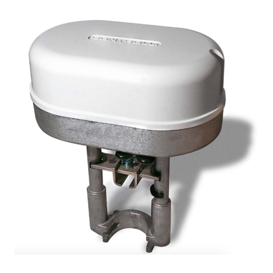
Globe Valves Actuators
with Electronic Fail Safe Function
POWER
MODEL
FORCE
SUPPLY
[N]
MVE206R
600
230Vac±10%
MVE206SR
600
230Vac±10%
APPLICATION AND USE
MVER is a flexible electro-mechanical actuator equipped with
electronic fail safe function device for the control of two-way and
three-way globe valves in:
•
Heating and cooling systems;
•
Air Handling Units;
•
District heating plants;
•
Industrial temperature control systems.
The actuator is endowed with an electronic emergency return fun-
ction which operates through the use of ultracapacitors whose life
is about 10 years if the actuator operates within the operation limits
declared in this data sheet.
The emergency position (retracted or extended stem) is set through
the use of a jumper which can be easily reached (look at paragraph
"DIP switches and jumper settings").
The actuator is supplied with totally discharged ultracapacitors and
at its first start a pre-charge phase of about 130s will be necessary.
During this phase all the functions of the actuator are inhibited and
the charge status of the ultracapacitors is signalled through 2 LEDs
(look at paragraph "Standard LEDs").
MVER can be controlled either by a proportional (modulating) signal
or by an increase/decrease (floating) signal.
It is easy to mount and connect the actuator. Direct mounting is pos-
sible to any CONTROLLI flanged valve. Linkage kits are available
for CONTROLLI threaded valves as well as for valves of other ma-
nufacturers. The actuator has a fine resolution (500 steps on the full
stroke range) for accurate fluid control and it is able to self-calibrate
on a different stroke without the need of any user action (this fun-
ction is DIP switch selectable on the field).
MVER has intelligent behavior and alarm functionality in case of
unexpected operation, feedback of alarms to the user is provided
by LEDs (GREEN and RED) on the upper control board.
N.B.: do not use the actuator if not coupled with its relating valve.
Controlli S.p.A.
16010 Sant'Olcese (GE)
Tel. 010 73 06 1
Fax. 010 73 06 870/871
www.controlli.eu
DESCRIPTION
long yoke, modulating/
floating control with position
emergency return with
totally open or closed valve
selectable through jumper
short yoke, modulating/
floating control with position
emergency return with
totally open or closed valve
selectable through jumper
1
Issue
st
OPERATION
The actuator is endowed with an electronic fail safe function which,
in case of power failure, allows to close (or to open) the valve and to
go back to the set position through the jumper.
The actuator commutes the control signal (modulating or 3-point flo-
ating) from the controller into a valve position. A modern brushless
DC motor in the actuator drives a gear train and a worm gear –
screw jack mechanism convert the motor revolutions into accurate
and repeatable linear movements.
Control Signal
MVER can be controlled by one of 2 main control types.
•
3-point floating ;
•
Modulating (or proportional) signal with filed selectable ran-
ge (e.g., 0-10Vdc, 2-10Vdc, 0-5/2-6Vdc, 5-10/6-10Vdc and
4-20mA).
Manual Override
There is a manual operation handle on the actuator. When it is lowe-
red (manual override ON), the power supply to the motor power sta-
ge circuitry is cut and the motor stops. The actuator can be opera-
ted manually and the valve positioned accordingly.
The manual override lever stays in position until it is raised again, then
board and motor will be powered again. At the end of this opera-
tion, the actuator moves to initial position (on the basis of DIP n. 1
setting), then it follows the control signal. When the manual override
is engaged the GREEN and the RED LED on the lower electronic bo-
ard are ON.
Manual operation handle can also be used to modify any DIP switch
setting or as re-set function after any alarm occurrence.
The actuator is supplied with the manual override lowered (ON). It
is not necessary to remove power supply to modify DIP switches set-
ting.
10/2014
DBL462e
MVE2xxR
Page 1
Advertisement
Table of Contents

Related Manuals for Controlli MVE2 R Series


Summary of Contents for Controlli MVE2 R Series
- Page 1 CONTROLLI flanged valve. Linkage kits are available board and motor will be powered again. At the end of this opera- for CONTROLLI threaded valves as well as for valves of other ma- tion, the actuator moves to initial position (on the basis of DIP n. 1 nufacturers.
-
Page 2: Control Signal
TECHNICAL FEATURES Position Feedback MVER utilizes a 2-10V position feedback (look at DIP n. 1 settings). MVE206R/SR Calibration Alimentazione F N 230Vac ±10%, 50-60Hz MVER ha both Auto and Manual Stroke Claibration. Actuator is de- Power consumption (running) 13VA/6W livered with DIP n. 7 set to Auto. Manual calibration is not necessary Power consumption (Holding) 11VA/5W unless maintenance is required on the valve or certain alarm fun-... -
Page 3: Maintenance
When the fluid temperature exceeds 120°C the actuator shall be mounted leaning 45°. (not 2TGB.F/3TGB.F PN16 required) T fluid MAX 120°C Controlli valves with threaded M40 T fluid ≥ 120°C T fluid ≥ 120°C AG51 connections (except for VSB/VMB/VSBF/VMBF PN16) - Page 4 GROUND CONNECTIONS Modulating Control (0-10Vcc) 230Vac Connect the ground terminal to the proper screw labelled with the ground symbol as shown in the picture here below. Controller Command + Command - Neutral ground terminal SAFETY PERSCRIPTIONS Use cable gland PG13,5 model (not supplied). 230 V products Install on the power supply line a protecting device to avoid LABEL...
-
Page 5: Dip Switches And Jumper Settings
DIP SWITCHES AND JUMPER SETTINGS Set the DIP switches according to the tables here below. In order to be sure that any modification has been accepted by the actuator, power down and power it up again or act on the manual operation handle. Factory settings Jumper for emergency return position selection (open jum-... - Page 6 TYPICAL RESET TROUBLE N° ERROR WHEN ACTUATOR BEHAVIOUR PROCE- SHOOTING DURE CONDITION Automatic Calibration SW7 OFF Manual Calibration SW7 ON The actuator push/pull 5 times The actuator push/pull 2 (unexpected stall) trying to times against endpoint Remove remove the possible obstacle. Calibrat- during calibration.
-
Page 7: Dimensions (Mm)
STANDARD LEDs Lower eletronic board N° ACTUATOR STATUS GREEN ON The actuator arrived at the extreme point of the stroke GREEN BLINKING The actuator is moving or arrived at the intermediate point of the stroke RED GREEN BLINKING Calibration or initialization phase ALTERNATING Manual control ON, the actuators ignores the control signal.
Need help?
Do you have a question about the MVE2 R Series and is the answer not in the manual?
Questions and answers