Table of Contents
Advertisement
Quick Links
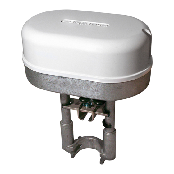
Globe Valves Actuators
Power
Model Force (N)
supply
MVE206
600
230Vac±10% long yoke, modulating/floating control
MVE210
1000
230Vac±10% long yoke, modulating/floating control
MVE215
1500
230Vac±10% long yoke, modulating/floating control
MVE206S
600
230Vac±10% short yoke, modulating/floating control
MVE210S
1000
230Vac±10% short yoke, modulating/floating control
MVE215S
1500
230Vac±10% short yoke, modulating/floating control
APPLICATION AND USE
The New MVE is a flexible electro-mechanical actuator for the
control of two and three way globe valves in:
• Heating and Cooling systems
• Air handling units
• District Heating plants
• Industrial Temperature Control systems.
The MVE can be controlled either by a proportional (modula-
ting) signal or by an increase/decrease (Floating) signal.
It is easy to mount and connect the actuator. Direct mounting
is possible to any CONTROLLI flanged valve. Linkage kits are
available for CONTROLLI threaded valves as well as for valves
of other manufacturers.
The Actuator has a fine resolution (500 steps on the full stroke
range) for exacting fluid control and it is able to self-calibrate
on a different stroke without the need of any user action (this
function is dip-switch selectable on the field).
The MVE has intelligent behavior and alarm functionality in
case of unexpected operation, feedback of alarms to the user is
provided by LEDs (Green and Red) on the control board.
OPERATION
The Actuator translates the control signal (modulating or 3 point
floating) from the controller into a valve position. A modern bru-
shless DC motor in the actuator drive a gear train and a worm
gear – screw jack mechanism convert the motor revolutions
into accurate and repeatable linear movements.
Control Signal
The MVE can be controlled by one of 2 main control types.
• 3 point floating ;
• Modulating (or proportional) signal with filed selectable ran-
ge (e.g. 0..10Vdc, 2..10Vdc, 0..5,2..6Vdc/5..10,6..10Vdc and
4-20mA).
Manual Override
There is a manual operation handle on the Actuator. When it is
lowered (manual override ON), the power supply to the motor
power stage circuitry is cut and the motor stops. The actuator
can be operated manually and the valve positioned accordingly.
The manual override lever latches in position until it is raised
again, then board and motor will be powered again. At the end
of this operation the actuator moves to initial position (on the
basis of DIP 1 setting) then it follows the control signal. When
the manual override is engaged the green and the red LED are
ON.
Manual operation handle can also be used to modify any dip-
switch setting or as re-set function after any alarm occurren-
ce. The actuator is supplied with the manual override lowered
(ON).
1
st
Issue
ISO 9001
Description
11/12
CONTROLLI S.p.A.
16010 SANT'OLCESE Genova - Italy
Tel.: +39 01073061
E-mail: info@controlli.eu
It is not necessary to remove power supply to modify dipswitch
setting, but, in this case, take care of 230Vac voltage.
Position Feedback
The MVE utilizes a 2-10V position feedback (look at DIP1 set-
ting).
Calibration
The MVE has both Auto and Manual Stroke Calibration, Sw.7.
In factory delivery the auto stroke calibration is enabled – ma-
nual calibration is not necessary unless maintenance is requi-
red on the valve or certain alarm functions are desired.
End Point Auxiliary Switches (with accessory DMVE)
End point switches change over when the valve is fully open
or closed. They are free contact with 24Vac max voltage to ter-
minals.
End point switches can be utilized to indicate valve stroke end
positions and for relay control of additional plant equipment.
When the actuators are controlled individually or in sequence,
it is possible to use the end switches to toggle when the valve
is fully open or fully closed. The auxiliary switch position accor-
ding to control signal (Y) is shown in the picture below.
Control
signal (Y)
0 ÷ 0,5V
0,5 ÷ 9,5V
9,5 ÷ 10V
Diagnostic
The actuator is provided with a self diagnostic algorithm able to
detect faulty conditions:
• stroke out of range 5-60 mm;
• unexpected stall condition (e.g. valve stuck);
• missing expected stall condition(e.g. link loose);
• voltage supply out of range.
These faulty conditions are signaled via the Green and Red
LED on the PCBA blinking accordingly (see Diagnostic – Alarm
Function Table).
1
Fax: +39 0107306870/871
Web: www.controlli.eu
MVE2XX
Relay
Relay
KC1
KC2
KC1 to K1 KC2 to K3
KC1 to K2 KC2 to K3
KC1 to K2 KC2 to K4
DBL394e
Advertisement
Table of Contents

Related Manuals for Controlli MVE2 Series


Summary of Contents for Controlli MVE2 Series
- Page 1 The MVE utilizes a 2-10V position feedback (look at DIP1 set- It is easy to mount and connect the actuator. Direct mounting ting). is possible to any CONTROLLI flanged valve. Linkage kits are available for CONTROLLI threaded valves as well as for valves Calibration of other manufacturers.
- Page 2 Color Aluminum / White (except for 2TGB.F/3TGB.F PN16) 2TGB.F/3TGB.F PN16 (not required) Weight (Kg) 1.5 kg Controlli valves with threaded M40 Dimensions (mm) Refer to the picture on the page 6 connections AG51 (except for VMB/VSB/VSBF/VMBF PN16) ASSEMBLING VMB/VSB/ VSBF/VMBF PN16...
- Page 3 ELECTRIC CONNECTIONS GROUND CONNECTION Remove the cover screw with a screwdriver and then remove Connect the ground terminal to the proper screw labelled with the cover as shown in the picture beside. the ground symbol as shown in the picture here below. MVE is equipped with a 6 poles removable terminal block for actuator control and with a not removable 2 poles terminal (F and N) for main control;...
- Page 4 DIPSWITCHES SETTINGS Set the dipswitches according to tables below. Power down and power up again the actuator or act on the manual override han- dle to be sure that settings will be recognized. N4170-06 Issue 11/12 DBL394e ISO 9001...
- Page 5 DIAGNOSTIC - ALARM FUNCTIONS Typical trouble N° Error When Actuator Behaviour Reset procedure shooting condition Automatic Calibration SW7 Manual Calibration SW7 The actuator pushes/pulls 5 times (unexpected stall) The actuator pushes/pulls trying to remove the possible 2 times against endpoint Calibrated obstacle.
- Page 6 STANDARD LEDs N° ACTUATOR STATUS GREEN ON The actuator arrived at the extreme point of the stroke read 2 GREEN BLINKING The actuator arrived at the intermediate point of the stroke read RED GREEN The actuator is reading the stroke or it is going to initial position BLINKING Manual control ON, the actuators ignores the control signal.
Need help?
Do you have a question about the MVE2 Series and is the answer not in the manual?
Questions and answers