Advertisement
Table of Contents
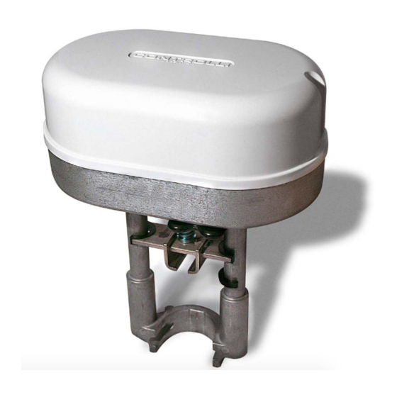
Servocomandi per valvole con dispositivo di ritorno in emergenza/
Valve actuators with emergency fail safe function
ISTRUZIONI DI MONTAGGIO / MOUNTING INSTRUCTIONS
Prestare attenzione alla presenza di tensione a 230Vac.
Attention to 230Vac voltage.
INSTALLAZIONE / INSTALLATION
1
3
1
Emissione / 1
Issue rev. d
a
st
T fluido/fluid ≥ 120°C
2
4
03/2020
CONTROLLI S.p.A. - 16010 Sant'Olcese (GE) - Italy
Tel. +39 010 73061 | Fax +39 010 7306870/871
info@controlli.eu | www.controlli.eu
MVE2XXR-65
T fluido/fluid MAX 120°C
T fluido/fluid ≥ 120°C
1
MVE2XXR
DIM266
Advertisement
Table of Contents

Related Manuals for Controlli MVE2 R Series


Summary of Contents for Controlli MVE2 R Series
- Page 1 T fluido/fluid MAX 120°C T fluido/fluid ≥ 120°C T fluido/fluid ≥ 120°C Emissione / 1 Issue rev. d 03/2020 DIM266 CONTROLLI S.p.A. - 16010 Sant’Olcese (GE) - Italy Tel. +39 010 73061 | Fax +39 010 7306870/871 info@controlli.eu | www.controlli.eu...
- Page 2 PASSACAVI CABLE GLAND Use cable gland PG13,5 model (not supplied). Utilizzare passacavi modello PG13,5 (non forniti). IP65 MODEL suitable with PG13,5 cable gland for cables with Ø varia- VERSIONE IP65 fornito con pressacavo PG13,5 per cavi con Ø varia- ble between 6 and 12 mm. bile tra 6 e 12 mm.
- Page 3 SCHEMA DI COLLEGAMENTO WIRING DIAGRAM Comando flottante a 3 punti 3 point floating control 3-point Floating Control Comando flottante a 3 punti 230Vac 230Vac Controller Controllore Open Aperto Y1 F Y1 F Close Chiuso Neutral Neutro Modulating control (0-10Vdc) Comando modulante (0-10Vdc) Modulating Control (0-10Vdc) Comando modulante (0-10Vdc) 230Vac...
- Page 4 REGOLAZIONE DEGLI INTERRUTTORI DIP E DEL JUMPER DIP SWITCHES AND JUMPER SETTINGS Set the DIP switches according to the tables here below. In order to Impostare gli interruttori DIP secondo le seguenti tabelle. Per fare in be sure that any modification has been accepted by the actuator, modo che le impostazioni vengano recepite è...
- Page 5 switch Azione Diretta Azione Inversa U = 2V U = 10V U= feedback U= feedback U = 10V U = 2V Modulante (MOD) (ingresso tra Y [+] e M [-]) 3 punti (INC) ( Y1 apre, Y2 chiude il contatto deve essere prelevato da M) Selezione sequenza con range definiti dal DIP n.
- Page 6 DIAGNOSTICA - FUNZIONE ALLARMI / DIAGNOSTIC - ALARM FUNCTIONS Comportamento Utilizzo Possibile Procedura di N° Errore Comportamento del servocomando servocomando problema ripristino Apprendimento corsa Apprendimento corsa automatico (DIP n. 7 manuale (DIP n. 7 ON) OFF) Il servocomando spinge e tira 2 volte Il servocomando spinge (scontro inatteso) per e tira 2 volte agli estremi...
- Page 7 Typical trouble LEDs Reset N° Error Actuator use Actuator behaviour shooting behaviour procedure condition Automatic calibration Manual calibration (DIP N. 7 OFF) (DIP N. 7 ON) The actuator pushes/pulls 2 times (unexpected stall) The actuator pushes/pulls 2 trying to remove the possible times against endpoint during obstacle.
- Page 8 COMPORTAMENTO STANDARD dei LED / STANDARD LEDs BEHAVIOUR Scheda inferiore di controllo Lower electronic control board Comportamento N° Stato servocomando N° LEDs behaviour Actuator status The actuator arrived at the extreme Il servocomando è arrivato all’estremo GREEN ON VERDE FISSO point of the stroke della corsa appresa The actuator is moving or arrived at the...
Need help?
Do you have a question about the MVE2 R Series and is the answer not in the manual?
Questions and answers