Table of Contents
Advertisement
Quick Links
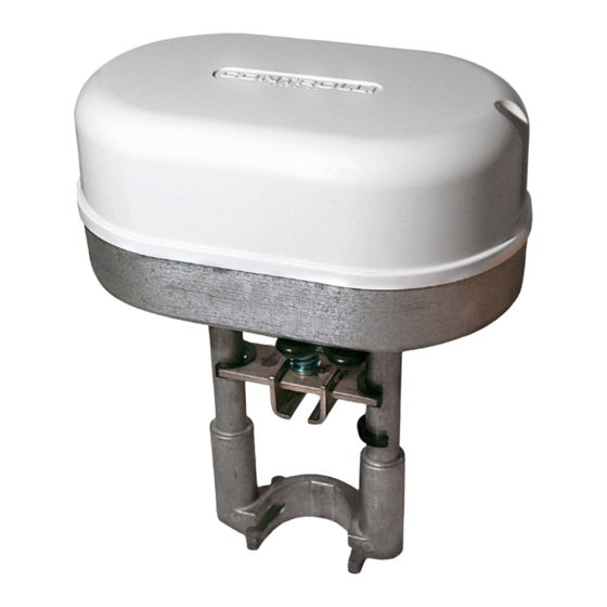
Globe Valves Actuators
Model
Force [N] Power supply
MVE206
600
230Vac±10%
MVE210
1000
230Vac±10%
MVE215
1500
230Vac±10%
MVE222
2200
230Vac±10%
MVE206S
600
230Vac±10%
MVE210S
1000
230Vac±10%
MVE215S
1500
230Vac±10%
MVE222S
2200
230Vac±10%
APPLICATION AND USE
MVE is a flexible electro-mechanical actuator for the control of two
and three way globe valves in:
•
heating and cooling systems
•
Air Handling Units
•
district heating plants
•
industrial temperature control systems.
MVE can be controlled either by a proportional (modulating) signal
or by an increase/decrease (Floating) signal.
It is easy to mount and connect the actuator. Direct mounting is pos-
sible to any CONTROLLI flanged valve. Linkage kits are available for
CONTROLLI threaded valves as well as for valves of other manufac-
turers (table page 3).
The actuator has a fine resolution (500 steps on the full stroke range)
for exacting fluid control and it is able to self-calibrate on a different
stroke without the need of any user action (this function is DIP switch
selectable on the field).
MVE has intelligent behaviour and alarm functionality in case of un-
expected operation, feedback of alarms to the user is provided by
LEDs (GREEN and RED) on the control board.
N.B.: Do not use the actuator if not coupled with its relating valve.
OPERATION
The actuator translates the control signal (modulating or 3 point
floating) from the controller into a valve position. A modern brushless
DC motor in the actuator drive a gear train and a worm gear – screw
jack mechanism convert the motor revolutions into accurate and
repeatable linear movements.
Control Signal
MVE can be controlled by one of 2 main control types.
•
3 point floating;
•
modulating (or proportional) signal with field selectable range
(e.g., 0-10Vdc, 2-10Vdc, 0-5/2-6Vdc, 5-10/6-10Vdc and 4-20mA).
Controlli S.p.A.
16010 Sant'Olcese (GE)
Tel. 010 73 06 1
Fax. 010 73 06 870/871
www.controlli.eu
Description
long yoke, modulating/
floating control
long yoke, modulating/
floating control
long yoke, modulating/
floating control
long yoke, modulating/
floating control
short yoke, modulating/
floating control
short yoke, modulating/
floating control
short yoke, modulating/
floating control
short yoke, modulating/
floating control
1
Issue rev. d
st
Manual Override
There is a manual operation handle on the actuator. When it is low-
ered (manual override ON), the power supply to the motor power
stage circuitry is cut and the motor stops. The actuator can be op-
erated manually and the valve positioned accordingly. The manual
override lever latches in position until it is raised again, then board
and motor will be powered again. At the end of this operation the
actuator moves to initial position (on the basis of DIP n. 1 setting) then
it follows the control signal. When the manual override is engaged
the GREEN and the RED LED are ON.
Manual operation handle can also be used to modify any DIP switch
setting or as re-set function after any alarm occurrence. The actua-
tor is supplied with the manual override lowered (ON).
t is not necessary to remove power supply to modify DIP switch set-
ting, but, in this case, take care of 230Vac voltage.
Feedback position
The actuator utilizes a 2-10V position feedback (look at DIP n. 1 set-
ting).
Calibration
The actuator has both auto and manual stroke calibration, DIP n. 7.
In factory delivery the auto stroke calibration is enabled – manual
calibration is not necessary unless maintenance is required on the
valve or certain alarm functions are desired.
01/2016
DBL394e
MVE2xx
Page 1
Advertisement
Table of Contents

Related Manuals for Controlli MVE2 Series


Summary of Contents for Controlli MVE2 Series
- Page 1 It is easy to mount and connect the actuator. Direct mounting is pos- it follows the control signal. When the manual override is engaged sible to any CONTROLLI flanged valve. Linkage kits are available for the GREEN and the RED LED are ON.
- Page 2 TECHNICAL CHARACTERISTICS End Point Auxiliary Switches (with accessory DMVE) End point switches change over when the valve is fully open or closed. They are free contact with 24V AC/DC, 4A max voltage to terminals. End point switches can be utilized to indicate valve stroke end posi- MVE206 MVE210 MVE215...
- Page 3 The actuator can be mounted with any orientation but never up-side down. When the fluid temperature exceed 120°C the actuator shall 2TGB.F/3TGB.F PN16 (not required) be mounted leaning 45°. Controlli valves with threaded M40 connections AG51 T fluid MAX 120°C (except for VSB/VMB/VSBF/VMBF PN16) T fluid ≥...
- Page 4 TERMINAL BLOCK SAFETY PRESCRIPTIONS 230 V products • Install on the power supply line a protecting device to avoid M Y1 Y2 short circuits (fuse or magneto-thermic) according to the spec- ifications in force; • in case of accidental removal of the cover to make sure that power is disconnected before working on the actuator or near it;...
- Page 5 DIP SWITCHES SETTINGS Set the DIP switches according to tables below. Power down and power up again the actuator or act on the manual override handle to be sure that settings will be recognized. Factory settings switch Direct Action Reverse Action U= feedback U= feedback U = 2V...
- Page 6 DIAGNOSTIC - ALARM FUNCTIONS LEDs Typical trouble shooting Reset N° Error Actuator use Actuator behaviour behaviour condition procedure Automatic calibration Manual calibration (DIP N. 7 OFF) (DIP N. 7 ON) The actuator The actuator pushes/ pushes/pulls 2 times pulls 2 times against (unexpected stall) trying endpoint during to remove the possible...
- Page 7 STANDARD LEDs BEHAVIOUR N° LED behaviour Actuator status GREEN ON The actuator arrived at the extreme point of the stroke read GREEN BLINKING The actuator arrived at the intermediate point of the stroke read RED GREEN BLINKING The actuator is reading the stroke or it is going to initial position Manual control ON, the actuators ignores the control signal.
Need help?
Do you have a question about the MVE2 Series and is the answer not in the manual?
Questions and answers