Table of Contents
Advertisement
Quick Links
Advertisement
Table of Contents

Related Manuals for Baker Hughes Panametrics PanaFlow Z3


Summary of Contents for Baker Hughes Panametrics PanaFlow Z3
- Page 1 Flow PanaFlow Z3 User’s Manual Panametrics.com 910-311 Rev. C April 2019...
- Page 3 Flow PanaFlow Z3 Ultrasonic Flow Meter for Liquid Custody Transfer Measurement User’s Manual 910-311 Rev. C April 2019 Panametrics.com 910-311 Rev. C...
- Page 4 [no content intended for this page]...
-
Page 5: Table Of Contents
Contents Chapter 1. Introduction Overview ......................1 Theory of Operation . - Page 6 Contents 3.5.3.4 Setting up Alarm Output ................33 3.5.4 Option Comm Slot-1 (optional).
- Page 7 Contents O-Ring Chemical Compatibility ................78 Appendix B.
- Page 8 Contents PanaFlow Z3 User’s Manual...
- Page 9 Preface Product Registration Thank you for purchasing a model PanaFlow Z3 from BakerHughes. Please register your product at https://www.bakerhughes.com/productregistration for product support such as the latest software/firmware upgrades, product information and special promotions. Services BakerHughes provides customers with an experienced staff of customer support personnel ready to respond to technical inquiries, as well as other remote and on-site support needs.
- Page 10 Preface WARNING! Make sure that power to the auxiliary equipment is turned OFF and locked out before you perform maintenance procedures on this equipment. Qualification of Personnel Make sure that all personnel have manufacturer-approved training applicable to the auxiliary equipment. Please make the factory aware of any customer visits so that any further support to the customer can occur immediately.
- Page 11 Preface Environmental Compliance RoHS The PanaFlow Z3 fully complies with RoHS regulations (Directive 2002/95/EC). Waste Electrical and Electronic Equipment (WEEE) Directive BakerHughes is an active participant in Europe’s Waste Electrical and Electronic Equipment (WEEE) take-back initiative (Directive 2012/19/EU). The equipment has required the extraction and use of natural resources for its production. It may contain hazardous substances that could impact health and the environment.
- Page 12 Preface [no content intended for this page] PanaFlow Z3 User’s Manual...
-
Page 13: Chapter 1. Introduction
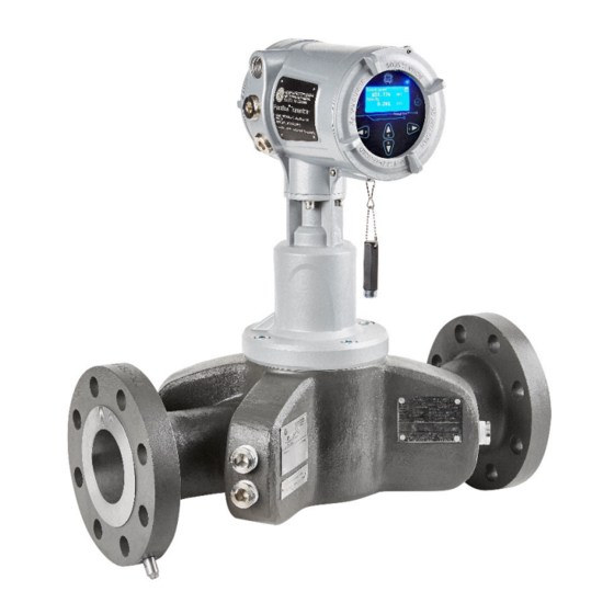
Chapter 1. Introduction Chapter 1. Introduction Overview The PanaFlow Z3 represents the latest generation of Panametrics ultrasonic flow meters. It is a three-path meter designed specifically for dependable, accurate and repeatable flow measurement of process liquids. Utilizing sleek industrial design and ultra-reliable electronics, the meter provides operators with a cost-effective choice when measurement accuracy and reliability are critical. -
Page 14: Theory Of Operation
Chapter 1. Introduction Theory of Operation 1.2.1 Transit-Time Flow Measurement In this method, two transducers serve as both ultrasonic signal generators and receivers. They are in acoustic communication with each other, meaning the second transducer can receive ultrasonic signals transmitted by the first transducer and vice versa. -
Page 15: Remote Transmitter Configuration
Chapter 1. Introduction Figure 2: The PanaFlow Z3 Flow Meter 1.3.2 Remote Transmitter Configuration The PanaFlow Z3 remote mount configuration allows users to place the XMT1000 Transmitter at a separate location from the flowcell. System configurations utilizing this remote mount option are supplied with a 2'' pipe mounting bracket for XMT1000 electronics, and require additional electrical connections to be made by the user. -
Page 16: Marking And Labeling
Chapter 1. Introduction Note: Actual design varies slightly with size. Figure 3: Panaflow Z3 Remote Mount Configuration 1.3.3 Marking and Labeling There are five tag plates affixed to the PanaFlow Z3 which provide details and information about your system. Three are located on the flowcell and two are located on the transmitter. -
Page 17: Specification Tag Plate
Chapter 1. Introduction Figure 5: Model Tag Plate (Remote Mount Tag Shown for Example) 1.3.3.2 Specification Tag Plate The pressure equipment is marked with the CE-mark as follows on the Specification Tag Plate (Figure 6). The Specification Tag Plate contains information pertaining to the build and test of the pressure vessel. In addition to the specifics of the following list: •... -
Page 18: Part String And Serial Number Tag Plate
Chapter 1. Introduction Figure 6: Specification Tag Plate (Remote Mount Tag Shown for Example) 1.3.3.3 Part String and Serial Number Tag Plate The Part String and Serial Number Tag Plate contains the specific configuration of the pressure vessel as well as final assembly date, BakerHughes serial number and customer tag information. -
Page 19: Chapter 2. Installation
Chapter 2. Installation Chapter 2. Installation Installation Guidelines This section provides general information with respect to the mechanical and electrical installation and should be thoroughly reviewed before the system is installed. To ensure safe and reliable operation of the PanaFlow Z3, the system must be installed in accordance with the established guidelines. -
Page 20: Unpacking The Panaflow Z3 System
Chapter 2. Installation Unpacking the PanaFlow Z3 System The PanaFlow Z3 will typically be packaged in a wooden crate, the size of which will depend on the size of product ordered. The flow meter will be secured by several 2x4 blocks to prevent shifting during transit. Simply remove these 2x4 braces to unpack the system. - Page 21 Chapter 2. Installation Figure 8: Lifting the PanaFlow Z3 System PanaFlow Z3 User’s Manual...
-
Page 22: Site Considerations
Chapter 2. Installation Site Considerations Proper installation of the PanaFlow Z3 is important to achieve optimum performance from the system. The following installation recommendations provide general guidelines of how this system should be installed. If the following recommendations cannot be met, please consult the factory for a more detailed review of the application to see what performance may be achievable. -
Page 23: Inner Diameter Matching
Chapter 2. Installation 2.3.1.3 Inner Diameter Matching To maintain optimal product performance, the inner diameter of the upstream sections and flange should be within 1% of the metering section inner diameter at the flange. The downstream matching is not as critical but should be of the same schedule and matched as closely as possible. -
Page 24: Local Mount Configuration Transducer Wiring
Chapter 2. Installation 2.4.1 Local Mount Configuration Transducer Wiring The wiring between transmitter and transducers has been completed at the factory. No further work is required on this portion of the wiring. Consult the XMT1000 Transmitter manual for customer connection wiring instructions. 2.4.2 Remote Mount Configuration Transducer Wiring Wiring the transmitter electronics to the remote flowcell setup is done by attaching the transmitter's cable gland to... - Page 25 Chapter 2. Installation Figure 12: Remote Mount Wiring Diagram PanaFlow Z3 User’s Manual...
- Page 26 Chapter 2. Installation [no content intended for this page] PanaFlow Z3 User’s Manual...
-
Page 27: Chapter 3. Programming
Chapter 3. Programming Chapter 3. Programming Introduction This chapter has instructions for programming various features of the PanaFlow™ Z3 flow transmitter. In this chapter, we will list all available options. The user can then change the User Preferences and Inputs/Outputs settings, Programming for flow measurements and Calibration to meet their needs. -
Page 28: Indicator Lights
Chapter 3. Programming 3.1.2 Indicator Lights • The blue light on the top right above the display is the Power Indicator that is normally lit when the instrument is powered. • The red light on the top left above the display is the Error Indicator. -
Page 29: Changing Display Format
Chapter 3. Programming 3.3.1.1 Changing Display Format To change Display Format, do the following steps and refer Figure 15. Press [] until the lock icon on the meter’s Measurement View display is highlighted, and press [ENTER]. In the Main Menu select [Display Format], then press [ENTER]. -
Page 30: Selecting A Channel Measurement To Display
Chapter 3. Programming Velocity Display Measurement Composite Composite Velocity 0.000 Channel 1 Volumetric (Act) Channel 2 Volumetric (Std) Channel 3 Mass (or) Composite Inv Vol Measure Velocity Fwd Vol Inventory Raw Velocity 0.000 Avg Vol Flow Rate Rev Vol Inventory Velocity Batch Vol Total Net Vol Inventory... -
Page 31: Totalizer Display
Chapter 3. Programming Display Measurement Channel 1 Ch 1 Velocity Composite Velocity 0.000 Channel 1 Volumetric (Act) Channel 2 Volumetric (Std) Channel 3 Mass Flow (or) Channel 1 Ch1/Inv Vol Measure Velocity Fwd Vol Inventory Raw Velocity 0.000 Avg Vol Flow Rate Rev Vol Inventory Ch 1 Velocity Batch Vol Total... - Page 32 Chapter 3. Programming Press [] button on the keypad until the [or ] is highlighted to stop or start the totalizing respectively. Press [] button on the keypad until the [] is highlighted to reset/clear the totalized measurements. Totalizer Totalizer/Composite Fwd Vol Total Composite Fwd Vol Batch...
-
Page 33: Log-In And Primary
Chapter 3. Programming 3.3.2 Log-in and Primary Pages To Log-in into the meter perform the following steps: Press [] until the lock icon on the meter’s Measurement View display is highlighted, then press [ENTER]. In the Main Menu Scroll down and select [Program], then press [ENTER]. -
Page 34: Selecting Units
Chapter 3. Programming 3.4.1 Selecting Units The operator can select the preferred units of measurements. Use steps as in Section 3.3.2 to navigate to the System settings page. Then highlight [Unit Settings] and press [ENTER], you will now have measurement types listed as in the Figure 20 below, for which you can select your preferred respective units. -
Page 35: Meter Settings
Chapter 3. Programming 3.4.2 Meter Settings In order to change the Language, display settings, System Date, Meter Tag, Label, Change password or view About meter, use steps as in section “Log-in and Primary Pages” to navigate to the System settings page. Then highlight [Meter Settings] and press [ENTER]. -
Page 36: Inputs And Outputs
Chapter 3. Programming Inputs and Outputs 3.5.1 Modbus Port Settings The XMT 1000 meter supports digital communications using the MODBUS/RTU protocol, with 3-wire RS-485 as the physical layer interfaces. Baud rate can be specified from 2400 to 115,200 bits per second (bps), with selectable parity, and number of stop bits (Default = 115200, Even, 1 Stop Bit). -
Page 37: Standard Analog Output
Chapter 3. Programming 3.5.2 Standard Analog Output The PanaFlow Z3 has one Analog Output and one Digital Output in Standard configuration. 3.5.2.1 Setting up Analog Output The PanaFlow Z3 meter has one Analog Output in standard configuration. For additional Analog outputs Optional I/O boards may be purchased. - Page 38 Chapter 3. Programming Table 4: Analog Output Error Handling with Path Error Handling set to ON Expected Composite Error displayed in Volumetric(Act) Ch1 in Error Ch2 in Error Ch3 in Error Meter behavior Analog Output Response E22: Measured mA proportional to the SingleChAccuracy Composite Measured Composite...
-
Page 39: Calibrating Analog Output
Chapter 3. Programming Measurement Type/Comp Measurement Type Input/Output Analog Output (Std) 4-20mA Velocity Analog Output (Std) Measurement Type Composite Volumetric (Act) Digital Output (Std) 4-20mA Base Value Channel 1 Volumetric (Std) Option Comm (Slot 1) Full Value Channel 2 Channel 3 Mass Flow Option I/O (Slot 2) Calibrate... -
Page 40: Standard Digital Output
Chapter 3. Programming Select [Percentage of Scale] and adjust the scale to 0.00% and press [ENTER], then verify the reading on the multimeter is 4.00mA within ±0.01mA. Then adjust the scale to 50.00% and press [ENTER], then verify the reading on the multimeter is 12.00mA within ±0.01mA. - Page 41 Chapter 3. Programming Pulse Input/Output Digital Output (Std) Polarity Polarity Analog Output (Std) Negative Pulse Measurement Digital Output (Std) Positive Pulse Value Frequency Option Comm (Slot 1) Pulse Width Alarm Option I/O (Slot 2) Pulse Measurement Type/Comp Measurement Type Polarity Composite Fwd Vol Batch Measurement Type...
-
Page 42: 3.5.3.2 Setting Up Frequency Output
Chapter 3. Programming 3.5.3.2 Setting up Frequency Output To program a Frequency Output, use steps as in Section 3.3.2 to navigate to the Input/Output settings page: In Meter Menu, select [Digital Output (Std)] and press [ENTER]. Then highlight [Frequency] option and press [ENTER]. -
Page 43: 3.5.3.3 Understanding The Error Handling Option
Chapter 3. Programming Frequency Measurement Type/Comp Input/Output Digital Output (Std) Measurement Type Measurement Type Velocity Analog Output (Std) Composite Volumetric (Act) Pulse Channel 1 Base Value Digital Output (Std) Volumetric (Std) Frequency Channel 2 Full Value Option Comm (Slot 1) Mass Flow Channel 3 Full Frequency... - Page 44 Chapter 3. Programming Table 10: Frequency Output Error Handling with Path Error Handling set to ON Expected Composite Error displayed in Volumetric(Act) Ch1 in Error Ch2 in Error Ch3 in Error Meter behavior Analog Output Response No Error Measured Frequency proportional Composite to the Measured Volumetric(Act)
-
Page 45: 3.5.3.4 Setting Up Alarm Output
Chapter 3. Programming 3.5.3.4 Setting up Alarm Output To program an Alarm Output, use steps as in Section 3.3.2 to navigate to the Input/Output settings page: In Meter Menu, select [Digital Output (Std)] and press [ENTER]. Then select [Alarm] option. Select the [Alarm State], [Alarm type], [Measurement] [Alarm Value]... - Page 46 Chapter 3. Programming Alarm State Alarm State Digital Output (Std) Alarm Input/Output Alarm State Normally Closed Analog Output (Std) Normally Closed Alarm Type Pulse Normally Open Normally Open Digital Output (Std) Measurement Type Frequency Option Comm (Slot 1) Fail Safe Fail Safe Alarm Value Alarm...
-
Page 47: Option Comm Slot-1 (Optional)
Chapter 3. Programming 3.5.4 Option Comm Slot-1 (optional) 3.5.4.1 Option Slot-1 Configured as HART Use steps as in section “Log-in and Primary Pages” to navigate to the Input/Output settings page. Select [Option Comm (Slot 1)] and press [ENTER]. Then select [HART] and press [ENTER]. -
Page 48: Option I/O Slot-2 (Optional)
Chapter 3. Programming 3.5.5 Option I/O Slot-2 (Optional) For extended I/O capability XMT1000 supports an Optional I/O that provides 2 additional Analog Outputs (AO-AO), with up to 2 Analog Inputs (AI-AI) or 2 RTD (R-R) inputs. See Table 13 for all available options. Table 13: Optional I/O available options Board Option # Input / Output Options Available... -
Page 49: 3.5.5.2 Option Io (Slot2): Calibrating Analog Output
Chapter 3. Programming Analog Output (S2:1) Input/Output Analog Output (S2:1) Measurement Type Measurement Type/Comp Option I/O (Slot 2) AO-AOAI-R-1000-3W Velocity Analog Output (Std) Measurement Type Composite AO-AOAI-R-1000-3W Analog Output (S2:1) Volumetric (Act) 4-20mA Channel 1 Digital Output (Std) Analog Output (S2:2) Base Value Volumetric (Std) Option Comm (Slot 1) -
Page 50: 3.5.5.3 Option Io (Slot2): Setting Up Analog Input
Chapter 3. Programming Select [Calibrate 20mA] and check if the reading on the multimeter reads 20.00mA ± 0.01mA. If the value on the multimeter is not 20.00mA ± 0.01mA, input the value read on the multimeter into the Calibrate 20mA value and press [ENTER]. -
Page 51: 3.5.5.4 Option Io (Slot2): Calibrating Analog Input
Chapter 3. Programming Analog Input (S2:3) Input/Output Option I/O (Slot 2) Analog Input (S2:3) Measurement Type AO-AOAI-R-1000-3W Measurement Type Analog Output (Std) Analog Output (S2:1) Temperature AO-AOAI-R-1000-3W 4-20mA Input Pressure Digital Output (Std) Analog Output (S2:2) Base Value Option Comm (Slot 1) Analog Input (S2:3) Full Value Option I/O (Slot 2) -
Page 52: 3.5.5.5 Option Io (Slot2): Calibrating Rtd Input
Chapter 3. Programming Figure 32: Option I/O Analog Input connections 3.5.5.5 Option IO (Slot2): Calibrating RTD Input Insert RTD sensor and master RTD in temperature bath and turn ON, and set it to desired temperature set point. Use steps as in Section 3.3.2 to navigate to the Input/Output settings page. Refer to Figure 31 above, select [Option I/O (Slot 2)] and press [ENTER]. -
Page 53: Programming Menu Options
Chapter 3. Programming Programming Menu Options The options in the Programming Page should be selected to best suit your application. The configurations selected in programming page are critical for accurate flow measurements. Incorrect programming settings can give erroneous measurements and impact accuracy. Note: Consult the factory or BakerHughes Services if you are unsure of the appropriate settings for your application. - Page 54 Chapter 3. Programming Table 15: Standard Fluid List Tracking On Tracking Off Other Other Water (0 to 260 C) Water (0 to 260C) Oil 22C Oil 22 C Sea Water Lube Oil Crude Oil Methanol (20 C) Ethanol Freon R12 Diesel Gasoline Liquid Nitrogen (-199C)
-
Page 55: Programming The Path Configuration
Chapter 3. Programming 3.6.3 Programming the Path Configuration Use steps as in Section 3.3.2 to navigate to the Programming page. Refer to Figure 36 for the Path configuration options. Select [Composite] and press [ENTER]. Scroll down and select [Path] and press [ENTER]. Select [Path Configuration], [Path Weights] [Path Error... -
Page 56: Programming Advanced Settings
Chapter 3. Programming Prigram/Composite Min Velocity Programming Limits Min Velocity UNIT: ft/s Pipe Composite Min Velocity Min Velocity Fluid -82.00 Channel 1 Max Velocity Path - 82.00 ft/s SAVE Channel 2 UNDO Min Vel Warn Limit Channel 3 Limits ALTER MOVE Max Vel Warn Limit Prigram/Composite... -
Page 57: Perform Software Upgrade
Chapter 3. Programming Option I/O board Note: Consult the factory or BakerHughes Services before you upgrade software. IMPORTANT: The upgrade process may wipe out the configurations. It is important to save a site file before beginning the upgrade process. Use USB flash drive 8GB or 16GB for upgrade. 32GB flash drive is not supported. - Page 58 Chapter 3. Programming [no content intended for this page] PanaFlow Z3 User’s Manual...
-
Page 59: Chapter 4. Error Codes And Troubleshooting
Chapter 4. Error Codes and Troubleshooting Chapter 4. Error Codes and Troubleshooting Introduction The PanaFlow Z3 flow transmitter is a reliable, easy to maintain instrument. When properly installed and operated, as described in Chapter 1, Installation, the meter provides accurate flow rate measurements with minimal user intervention. -
Page 60: Multi-Channel Error
Chapter 4. Error Codes and Troubleshooting Defective/Damaged cables, transducers, couplant, buffer or electronics. After you have tried eliminating/correcting for any most likely causes mentioned above, if error still exists, also check Process/flow conditions change. Excessive turbulence. Discontinuities in fluid characteristics such as multi-phase flow, flashing, pockets of gas, presence of bubbles or solid particles, cavitation or rapidly changing fluid type. - Page 61 Chapter 4. Error Codes and Troubleshooting Figure 41: Viewing Flow Diagnostics Table 17: Flow Error description and Recommended Actions Error Code Problem Cause Recommended Action E1: SNR The Signal to Noise The acoustic signal from the Check if the Active Tw measurement ratio is low process is very low.
- Page 62 Chapter 4. Error Codes and Troubleshooting Table 17: Flow Error description and Recommended Actions Error Code Problem Cause Recommended Action E3: Velocity Range The measured velocity This error may be caused by Make sure the actual flow rate is exceeds programmed incorrect programming, within the programmed Error limits limits...
- Page 63 Chapter 4. Error Codes and Troubleshooting Table 17: Flow Error description and Recommended Actions Error Code Problem Cause Recommended Action E23: Multi Channel Two or more Two or more measurement Check individual channel errors, refer Accuracy measurement channels are in error; to this table for recommended channels are in error accuracy of the...
-
Page 64: Fluid And Pipe Problems
Chapter 4. Error Codes and Troubleshooting Fluid and Pipe Problems If preliminary troubleshooting with the Error Code Messages and the Diagnostic Parameters indicates a possible problem, proceed with this section. Measurement problems fall into two categories: • Fluid problems • Pipe problems Read the following sections carefully to determine if the problem is related to the fluid or the pipe. -
Page 65: Transducer/Buffer Problems
Chapter 4. Error Codes and Troubleshooting Transducer/Buffer Problems Ultrasonic transducers are rugged, reliable devices. However, they are subject to physical damage from mishandling and chemical attack. The following list of potential problems is grouped according to transducer type. Contact BakerHughes if you cannot solve a transducer-related problem. 4.5.1 Wetted Transducer Problems •... -
Page 66: Service Test Points
Chapter 4. Error Codes and Troubleshooting Service Test Points Service tests points can be found on the PanaFlow Z3 Main board just inside the front cover. There are 6 pins found on the bottom left front side of the main PCB that are accessible to service personnel. These test points are easily connected by standard oscilloscope probes and allow the service person to look at critical signals. -
Page 67: System Errors (S-Errors)
Chapter 4. Error Codes and Troubleshooting System Errors (S-Errors) These errors are from the Flow subsystem. The system errors have 4 types of indications. Indicator Warning Error Fault The indicator is just a notification to the operator, no action is needed. The warnings are usually indicative of an operator error. - Page 68 Chapter 4. Error Codes and Troubleshooting Table 20: System Error Description and Recommended Actions Error Code Error Message Description / Recommended Action S17: Temperature Temperature error Error: Temperature of the electronics is outside the pre-defined operating range. Make sure that the ambient temperature is not outside the meter operating range S18: Driver Fault...
-
Page 69: Communication Errors (C-Errors)
Chapter 4. Error Codes and Troubleshooting Communication Errors (C-Errors) The communication error indicates that the Transmitter subsystem has lost communication with Flow measurement sub-system or the Option I/O sub-system. Table 21: Communication Error Description and Recommended Actions Error Code Error Message Description / Recommended Action C1: Flow COMM Error Flow board communication... -
Page 70: Transmitter Errors
Chapter 4. Error Codes and Troubleshooting Transmitter Errors These errors are from the Transmitter subsystem. Should you encounter one of the Transmitter Errors, follow recommended actions and contact BakerHughes factory. Table 22: Transmitter Error Description and Recommended Actions Error Code Error Message Description / Recommended Action X1: MCU RAM Error... -
Page 71: 4.10 Option I/O Errors
Chapter 4. Error Codes and Troubleshooting 4.10 Option I/O Errors Table 23: Option I/O Errors Description Error Code Error Message Description A1:AnalogCh(S2:3) Error! ADC Channel(S2:3) is not Analog input /RTD input is not working. If error responding persists after power cycle, contact BakerHughes factory A2:AnalogCh (S2:4) Error! ADC Channel(S2:4) is not... -
Page 72: 4.11 Meter Health With Diagnostics Data
Chapter 4. Error Codes and Troubleshooting 4.11 Meter Health with Diagnostics Data To determine the health of the meter, PanaFlow Z3 has built-in diagnostic parameters. Please refer to the table below for diagnosing any problems with the system. If the meter shows errors and the diagnostics data indicate issues, fill in the User/Service record appendix before contacting BakerHughes factory. - Page 73 Chapter 4. Error Codes and Troubleshooting Parameter Description Good Active Tw Up Time in upstream Within 20% of the Over or under 20% of the transducer buffer programmed Static Tw programmed Static Tw value value Active Tw Down Time in downstream Within 20% of the Over or under 20% of the transducer buffer...
- Page 74 Chapter 4. Error Codes and Troubleshooting [no content intended for this page] PanaFlow Z3 User’s Manual...
-
Page 75: Chapter 5. Maintenance And Service
Chapter 5. Maintenance and Service Chapter 5. Maintenance and Service Hardware Maintenance and Inspection WARNING! Before opening the vessel, it must not contain any pressure! This warning pertains to all three interfaces described below (flange interface, transmitter connection and sensor ports). -
Page 76: Servicing The Pipe Interface
Chapter 5. Maintenance and Service 5.1.1 Servicing the Pipe Interface WARNING! Before opening the meter body, it must not contain any pressure. Only properly trained personnel (i.e. pipe fitters) should service the pipe flanges. The proper gasket material, nuts, bolts, nut and bolt torque and tightening sequence should always be used. 5.1.2 Servicing the Sensor Ports or Transmitter Interface WARNING! - Page 77 Chapter 5. Maintenance and Service Figure 44: Upstream “A” Plane and “B” Plane Sensor Quadrants – View 1 (Top) Figure 45: Upstream “A” Plane Sensor Quadrant – View 2 (Front) PanaFlow Z3 User’s Manual...
-
Page 78: Instructions To Rotate The Xmt1000 Transmitter
Chapter 5. Maintenance and Service Figure 46: Upstream “A” Plane Sensor Quadrant – View 3 (Bottom) 5.1.2.3 Instructions to Rotate the XMT1000 Transmitter WARNING! All equipment should be de-energized prior to servicing. Before performing any rotation of the XMT1000 Transmitter, ensure that the enclosure is de-energized. Locate the back of the XMT1000 Transmitter and remove the rear enclosure cover by turning it counter-clockwise. -
Page 79: Removing The Xmt1000 Transmitter
Chapter 5. Maintenance and Service Figure 47: Disassembly Required for XMT1000 Transmitter Rotation (Back View) 5.1.2.4 Removing the XMT1000 Transmitter Only properly trained personnel and qualified service technicians should remove the XMT1000 Transmitter from the flow meter adapter. The XMT1000 Transmitter contains transducer wiring and sensitive electronics. Modification or alteration in any manner may impact performance of the system. -
Page 80: Service
Chapter 5. Maintenance and Service Service The PanaFlow Z3 is a calibrated process flow meter. Local requirements may not allow field replacement of any components in this flow metering system without a proper calibration of the entire system at an approved calibration facility. -
Page 81: Appendix A. Specifications And Model Configurations
Appendix A. Specifications and Model Configurations Appendix A. Specifications and Model Configurations Operation and Performance Fluid Types Liquids: acoustically conductive fluids, including most clean liquids, and many liquids with small amounts of entrained solids or gas bubbles. Flow Measurement • Correlation transit time model Accuracy 3 to 24 in (80 to 600 mm) -
Page 82: Meter Body/Transducer
Appendix A. Specifications and Model Configurations Meter Body/Transducer Meter Body Materials Low temperature carbon steel: ATSM SA352 Gr. LCC Stainless steel: ASTM SA351 Gr. CF8M Duplex stainless steel: ASTM SA995 GR. CD3MWCuN Transducer System and Material LX transducers with inserts 316 SS or A479 UNS S32760 (Duplex) Wetted components Seals: FKM or EPDM Process Fluid Temperature Range Local mount: -40°F to 302°F (-40°C to 150°C) Remote mount: -40°F to 302°F (-40°C to 150°C) -
Page 83: Transmitter
Appendix A. Specifications and Model Configurations Transmitter Enclosures Powder coated aluminum or stainless steel (SS316) conformal coated Classifications US/CAN: Class I, Division 1, Groups B, C, D; Class I, Zone 1, Ex db IIB+H2 T6...150C; IP 66/67 Type 4X SINGLE SEAL ATEX/IECEx: Ex db IIB+H2 T6...150C FISCO outputs Ta = -40°C to +65°C, IP 66/67 Operating: -40°F to 149°F (-40°C to +65°C*) - Page 84 Appendix A. Specifications and Model Configurations • One or two 4 to 20 mA isolated inputs, 24-VDC loop power, NAMUR NE43 • One or two isolated, three-wire RTD (temperature) inputs, –148°F to 662°F (–100°C to 350°C), 100 Ohm or 1000 Ohm platinum.
-
Page 85: Serial Number Information
Appendix A. Specifications and Model Configurations Serial Number Information PanaFlow Z3 User’s Manual... - Page 86 Appendix A. Specifications and Model Configurations PanaFlow Z3 User’s Manual...
- Page 87 Appendix A. Specifications and Model Configurations Note: Other meter body materials can be offered on request. Please consult factory. PanaFlow Z3 User’s Manual...
-
Page 88: Pressure Derating Information
Appendix A. Specifications and Model Configurations Pressure Derating Information ASME B16.5 SA-352 GR. LCC 1600 1400 1200 1000 45.5 216.5 TEMPERATURE (°F) SA-351 GR. CF8M 1600 1400 1200 1000 45.5 216.5 TEMPERATURE (°F) SA-995 GR. CD3MWCuN 1600 1400 1200 1000 45.5 216.5 TEMPERATURE (°F) - Page 89 Appendix A. Specifications and Model Configurations EN 1092-1 352 GR. LCC (GROUP 3E1) 102.5 TEMPERATURE ( °C) SA-351 GR. CF8M (GROUP 14E0) 102.5 TEMPERATURE (°C) SA-995 GR. CD3MWCuN (GROUP 16E0) 102.5 TEMPERATURE (°C) PN 10 PN 16 PN 25 PN 40 PN 63 Figure 49: Pressure derating information as per EN 1092-1 DIN standards PanaFlow Z3 User’s Manual...
-
Page 90: O-Ring Chemical Compatibility
Appendix A. Specifications and Model Configurations O-Ring Chemical Compatibility O-rings composed of both EPDM and Viton are used in the Panaflow Z3 flowmeter. Certain process fluids may detriment the performance of these O-rings, therefore impacting the effectiveness and safety of the system overall. Typical applications of O-rings composed of EPDM or Viton: •... - Page 91 Appendix A. Specifications and Model Configurations TABLE-1 APPROX. SL. NO PIPE SIZE FLANGE RATING ASSY WEIGHT.(Kg) 19.2 43.2 ASME 150# RF (WN) [152] [508] [487] [1117] [1097] 19.4 43.5 ASME 300# RF (WN) [165] [508] [494] [1117] [1103] 19.4 43.5 ASME 600# RF (WN) [165] [508]...
- Page 92 Appendix A. Specifications and Model Configurations TABLE-1 (CONT..) TABLE-1 (CONT..) APPROX. APPROX. SL. NO PIPE SIZE FLANGE RATING SL. NO PIPE SIZE FLANGE RATING ASSY WEIGHT.(Kg) ASSY WEIGHT.(Kg) 16.0 28.0 28.8 52.8 27.5 40.6 64.6 ASME 150# RF (WN) ASME 150# RF (WN) [406] [711] [732]...
- Page 93 Appendix A. Specifications and Model Configurations "CX" ALLOW 12.0 [305] MINIMUM RECOMMENDED MAINTENANCE CLEARANCE ON EITHER SIDE "A" "CZ" ALLOW 12.0 [305] MINIMUM "Z" RECOMMENDED MAINTENANCE CLEARANCE ON EITHER SIDE "X" "C" "CY" "Y" ALLOW 12.0 [305] MINIMUM RECOMMENDED MAINTENANCE CLEARANCE ON EITHER SIDE "D"...
- Page 94 Appendix A. Specifications and Model Configurations TABLE-1 APPROX. SL. NO PIPE SIZE FLANGE RATING ASSY WEIGHT.(Kg) ASME 150# RF (WN) [152] [508] [279] [1117] [889] 11.3 35.3 ASME 300# RF (WN) [165] [508] [285] [1117] [895] 11.3 35.3 ASME 600# RF (WN) [165] [508] [285]...
- Page 95 Appendix A. Specifications and Model Configurations TABLE-1 (CONT..) TABLE-1 (CONT..) APPROX. APPROX. SL. NO PIPE SIZE FLANGE RATING SL. NO PIPE SIZE FLANGE RATING ASSY WEIGHT.(Kg) ASSY WEIGHT.(Kg) 20.6 44.6 ASME 150# RF (WN) 27.5 32.4 56.4 [406] [711] [524] [1320] [1133] ASME 150# RF (WN)
- Page 96 Appendix A. Specifications and Model Configurations "CX" ALLOW 12.0 [305] MINIMUM RECOMMENDED MAINTENANCE CLEARANCE ON EITHER SIDE "CZ" ALLOW 12.0 [305] MINIMUM "Z" RECOMMENDED MAINTENANCE CLEARANCE ON EITHER SIDE "A" "X" "C" "CY" ALLOW 12.0 [305] MINIMUM RECOMMENDED MAINTENANCE "Y" CLEARANCE ON EITHER SIDE "D"...
- Page 97 Appendix A. Specifications and Model Configurations CUSTOMER TO SUPPLY 2 INCH PIPE TRANSMITTER HEAD RIGID CONDUIT AND CONDUIT SEALS WHICH ARE TO BE SUPPLIED BY CUSTOMER NOT SHOWN FOR SIMPLICITY, SEE NOTE 6 & 7 FLOWCELL ATEX/IECEx FLOWCELL SHOWN 3/4" NPT ENTRY, SEE NOTE 6. CABLE GLAND PROVIDED FOR ATEX/IECEx SYSTEMS ONLY USA/CANADA SYSTEM SHOWN 6X RIGHT ANGLE SMB PLUG CONNECTORS.
- Page 98 Appendix A. Specifications and Model Configurations INTRINSICALLY SAFE SEE MANUAL AND BHGE DRAWING 702-2040 FOR BARRIER PROVIDED WITH WIRING DETAILS FOUNDATION FIELDBUS ONLY REMOVE LABEL AFTER INSTALLATION 1/2" NPT TO 3/4" NPT ADAPTER 6X RIGHT ANGLE MCX PLUG CONNECTORS. CONNECT PER LABELING ON CABLE AND BOARD CABLE GLAND PRESENT FOR SILKSCREEN...
-
Page 99: Appendix B. Data Records
Appendix B. Data Records Appendix B. Data Records Electronics B.1.1 Data Entry Record complete and detailed service data for the PanaFlow Z3 in Table 25 below. Make additional copies of the table as needed. Table 25: Service Record Date Description of Service Performed By PanaFlow Z3 User’s Manual... -
Page 100: Initial Settings
Appendix B. Data Records Table 25: Service Record (cont.) Date Description of Service Performed By Initial Settings PanaFlow Z3 User’s Manual... - Page 101 Appendix B. Data Records The values for the initial measurement settings immediately after initial installation of the meter and verification of proper operation should be entered in Table 26 below. Table 26: Initial Settings Parameter Initial Value Velocity Volumetric Mass Flow Forward Batch Totals Reverse Batch Totals Totalizer Time...
- Page 102 Appendix B. Data Records Table 26: Initial Settings (cont.) Parameter Initial Value Channel 2 Delta T Channel 2 Up Signal Quality Channel 2 Down Signal Quality Channel 2 Up Amp Disc Channel 2 Down Amp Disc Channel 2 SNR on Up Channel 2 SNR on Down Channel 2 Time in Buffer on Up Channel 2 Time in Buffer on Down...
-
Page 103: Diagnostic Parameters
Appendix B. Data Records Diagnostic Parameters The values for the diagnostic parameters immediately after initial installation of the meter and verification of proper operation should be entered in Table 27 below. These initial values can then be compared to current values to help diagnose any future malfunction of the system. - Page 104 Appendix B. Data Records [no content intended for this page] PanaFlow Z3 User’s Manual...
-
Page 105: Appendix C. Modbus Map
Appendix C. Modbus Map Appendix C. Modbus Map Input Registers Map PanaFlow Z3 User’s Manual... - Page 106 Appendix C. Modbus Map Note: Most Modbus Masters add an offset of 1 to the actual register addresses. For Example: Meter Modbus address = 0x8200, Address to input in the Modbus master application = 0x8201 PanaFlow Z3 User’s Manual...
-
Page 107: Appendix D. Ce Mark Compliance
Appendix D. CE Mark Compliance Appendix D. CE Mark Compliance Introduction For CE Mark compliance, the PanaFlow Z3 flow meter must be wired in accordance with the instructions in this appendix. IMPORTANT: CE Mark compliance is required for all units intended for use in EU countries. Wiring The PanaFlow Z3 must be wired with the recommended cable, and all connections must be properly shielded and grounded. - Page 108 Appendix D. CE Mark Compliance [no content intended for this page] PanaFlow Z3 User’s Manual...
-
Page 109: Warranty
Warranty Warranty Each instrument manufactured by Panametrics flow meter from Baker Hughes company is warranted to be free from defects in material and workmanship. Liability under this warranty is limited to restoring the instrument to normal operation or replacing the instrument, at the sole discretion of Panametrics & Panametrics Flow meter. Fuses and batteries are specifically excluded from any liability. - Page 110 Warranty [no content intended for this page] PanaFlow Z3 User’s Manual...
- Page 111 Panametrics Certification & Safety Statements Certification and Safety Statements for PF10-Zx Ultrasonic Flowmeter up to 3750/3750 psig When installing this apparatus, the following requirements must be met: • The end user must ensure that any cable and cable entry devices used with the equipment are suitable for use at temperatures above 90°C.
- Page 112 Certification & Safety Statements for PanaFlow PF10-Zx Apr 2019 • Field connections to the XMT1000 (e.g. ultrasonic transducers, accessories, or similar peripherals) shall be appropriately certified for the location and installed in accordance with wiring method requirements of the local electrical code as applicable. •...
- Page 113 Certification & Safety Statements for PanaFlow PF10-Zx Apr 2019 REMOTE MOUNT CERTIFICATION TAG FLOWCELL SPECIFICATION TAG 133M6993, Rev. B 101 of 104...
- Page 114 Certification & Safety Statements for PanaFlow PF10-Zx Apr 2019 SERIAL NUMBER AND MODEL CODE TAG Connection and Wiring Diagram REMOTE MOUNT WIRING 133M6993, Rev. B 102 of 104...
- Page 115 Certification & Safety Statements for PanaFlow PF10-Zx Apr 2019 LOCAL MOUNT WIRING 133M6993, Rev. B 103 of 104...
- Page 118 Tel: +353 61 470200 E-mail: gesensingorders@bakerhughes.com Copyright 2020 Baker Hughes company. This material contains one or more registered trademarks of Baker Hughes Company and its subsidiaries in one or more countries. All third-party product and company names are trademarks of their respective holders.
Need help?
Do you have a question about the Panametrics PanaFlow Z3 and is the answer not in the manual?
Questions and answers