Advertisement
Quick Links
Advertisement

Related Manuals for Baker Hughes Panametrics XMTCpro


Summary of Contents for Baker Hughes Panametrics XMTCpro
- Page 1 XMTCpro Thermal Conductivity Binary Gas Analyzer User’s Manual BH078C11 EN A panametrics.com...
- Page 3 Dec 2024 panametrics.com Copyright 2024 Baker Hughes company. This material contains one or more registered trademarks of Baker Hughes Company and its subsidiaries in one or more countries. All third-party product and company names are trademarks of their respective holders.
- Page 4 [no content intended for this page]...
- Page 5 Preface Services Panametrics provides customers with an experienced staff of customer support personnel ready to respond to technical inquiries, as well as other remote and on-site support needs. To complement our broad portfolio of industry-leading solutions, we offer several types of flexible and scalable support services including: Training, Product Repairs, Service Agreements and more.
- Page 6 Preface Qualification of Personnel Make sure that all personnel have manufacturer-approved training applicable to the auxiliary equipment. Personal Safety Equipment Make sure that operators and maintenance personnel have all safety equipment applicable to the auxiliary equipment. Examples include safety glasses, protective headgear, safety shoes, etc. Unauthorized Operation Make sure that unauthorized personnel cannot gain access to the operation of the equipment.
- Page 7 Contents Chapter 1. Features and capabilities Introduction ........................1 Basic features .
- Page 8 Contents 4.10 Proof Tests (SIL Only) ......................29 4.10.1 Test Solenoids.
- Page 9 Contents Appendix E. Menu Maps Dashboard & Main Menu ....................65 Measure Menu .
- Page 10 Contents [no content intended for this page] viii XMTCpro User’s Manual...
- Page 11 Chapter 1. Features and capabilities Introduction This chapter introduces you to the features and capabilities of the Panametrics XMTCpro thermal conductivity based binary gas analyzer. The following topics are discussed: • Description and basic features of the XMTCpro • Theory of operation •...
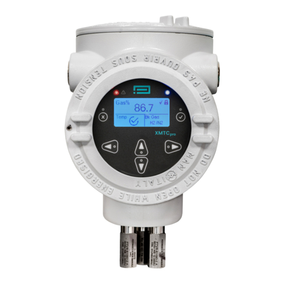
- Page 12 Chapter 1. Features and capabilities Configuration and certification information Mounting holes Cable entries (2 on each side) Removable top cover Removable front cove (secured with and adjustment screw) Multi-parameter display Magnetic keypad Flame arrestors (gas inlet/outlet) and breather Figure 1: External components of the XMTCpro Theory of operation The XMTCpro measures the concentration of the measurand gas in a binary or pseudo-binary gas mixture, by monitoring the changes in the thermal conductivity of the gas mixture dry air.
- Page 13 Chapter 1. Features and capabilities Air/N Figure 3: Relative thermal conductivity of some common gases. Appendix J , lists the relative thermal conductivities of common gases. System description As an extractive industrial process gas analyzer, the XMTCpro requires the use of a sample conditioning system. This mandatory sample conditioning system may vary in design (required components) depending on process conditions.
- Page 14 Chapter 1. Features and capabilities As shown in Figure 5, the XMTCpro has three ports: a sample gas inlet, outlet and breather port. The breather port serves as a vent for safety, for IEC 60079-1 compliance. Breather port In/Out ports (Safety vent) Figure 5: XMTCpro Ports 1.5.2...
- Page 15 Chapter 1. Features and capabilities Applications The stable and accurate thermal conductivity sensor, certified globally for use in hazardous area environments, make the XMTCpro the tool of choice for use in: Hydrogen economy • H in various applications along the hydrogen value chain. Metals industry •...
- Page 16 Chapter 1. Features and capabilities [no content intended for this page] XMTCpro User’s Manual...
- Page 17 It is the responsibility of the end user to ensure that any site personnel who are performing installation, commissioning and maintenance have been trained in proper site procedures for working with and around Baker Hughes supplied equipment, per Safe Work Practices.
- Page 18 Chapter 2. Installation Mount the sample system as close to the process sample point as possible. Once the sample system is mounted, connect all inlet and outlet lines via the 1/4" (or regional equivalent) compression fittings on the sample system. The sample line leading from the process to the sample system should be of 1/4"...
- Page 19 Chapter 2. Installation Wiring the Analyzer This section describes how to make all necessary electrical connections to the XMTCpro sample system. Do not apply power during installation. IMPORTANT: Installation shall be in accordance with the installation instructions and the National Electrical Code® ANSI/NFPA 70, the Canadian Electrical Code C22.1, or IEC/EN 60079-14, as applicable.
- Page 20 Chapter 2. Installation 2.4.2 CE Mark Requirements WARNING! To meet CE Mark requirements, you must shield and ground all electrical cables as described in Appendix G. CE Mark Compliance on page 81 . WARNING! CE Mark compliance is required for all units installed in EU countries. WARNING! Cable entry devices of an approved flameproof design are required.
- Page 21 Chapter 2. Installation Port D Port A J3/TB3 [Relay Outputs 5 & 6] J1/TB1 [20-28V DC Input] Internal grounding point Accepts 28 - 16 AWG wire Accepts 28 – 12 AWG wire PIN description PIN description 5-NO (+) PSU IN (-) PSU IN 5-NC 6-NO...
- Page 22 Chapter 2. Installation Connect the appropriate leads per the wiring diagram in Figure 8. CAUTION! Connecting the +24 VDC lead to any terminal except TB1-1 will damage the XMTCpro. Complete the following steps to safely finalize the wiring of the device. Carefully plug the TB1, TB2, TB3, TB10 connectors back onto the printed circuit board, and reinstall the cover on the XMTCpro.
- Page 23 Chapter 2. Installation The apparatus cannot be repaired by the user. Specifically, the flameproof design was assessed with non-standard thread lengths and cemented joints; these cannot be repaired. Contact Panametrics service team for assistance. Connecting cables shall be mounted securely and protected from mechanical damage, pulling and twisting. Cable entry devices of a suitably certified flameproof design are required.
- Page 24 Chapter 2. Installation [no content intended for this page] XMTCpro User’s Manual...
- Page 25 Chapter 3. Features and capabilities Chapter 3. Features and capabilities Introduction This chapter provides information on operating the XMTCpro analyzer. The following topics are discussed: • Powering up the XMTCpro • Basic sample gas considerations If you have not already done so, please read Chapter 2, Installation on page 7, for details on mounting and wiring the XMTCpro and the sample system.
- Page 26 Chapter 3. Features and capabilities [no content intended for this page] XMTCpro User’s Manual...
- Page 27 Chapter 4. Programming with HMI Chapter 4. Programming with HMI The XMTCpro is factory-programmed and ready for use. You may access its programming using the HMI or a Modbus Client Software through your PC. The XMTCpro Keypad Along with the 128 x 64, monochrome LCD, the XMTCpro analyzer includes a 6-key magnetic keypad (See Figure 9). The decal cutout for each key contains a hall effect sensor, pushbutton switch and visible red LED.
- Page 28 Chapter 4. Programming with HMI Gas% 1.80 Cell Status BK Gas H2/Air Main Menu Main Menu Main Menu About Login Measure Outputs Alarms Diagnose Outputs Menu Measure Menu Measure Measure Outputs Outputs Gas% 4-20 mA Out1 Gas% 4-20 mA Out1 Cell Temp 4-20 mA Out2 42.00...
- Page 29 Chapter 4. Programming with HMI Dashboard The XMTCpro dashboard screen provides real time monitoring of key parameters related to the analyzer performance. Gas %: This shows the percentage of the signal gas in the gas mixture. It provides a direct measurement of the signal gas concentration.
- Page 30 Chapter 4. Programming with HMI Login Menu The “Login” menu provides the operator with two functionalities: Log on to the unit Change the password for a user profile Logout Login Password Login Change Password Logout The unit comes configured with 3 different user access levels (see figure below). Each level defines the information the different users can access and edit, i.
- Page 31 Chapter 4. Programming with HMI 4.4.1 Login as User To log in as a user to the device, go to the logins menu and select “Login As”. You will be provided with 3 options, select “User”. Now the unit will prompt the password for that profile. Enter the password and press OK. If login is successful, you will be redirected to the dashboard screen and you will see an open padlock icon with the number 1 in it, indicating “USER”...
- Page 32 Chapter 4. Programming with HMI 4.4.4 Change Password The Change Password menu lets you change the password for the “USER” or “ADMIN” profile for the unit. To change the password for a specific profile you need to be logged in first. In case, you are not logged in and try to change the password you will be presented with a “LOGIN FIRST”...
- Page 33 Chapter 4. Programming with HMI The early under, early over, gas under and gas over alarms are associated with trip points and will trigger when the gas% exceeds the specified trip point. See Figure 11 to determine how Early low/high alarms and trip points function. Alarm High Early High Gas%...
- Page 34 Chapter 4. Programming with HMI 4.5.1 Analog Alarms The “Analog Alarms” menu lets you enable or disable error handling for the secondary 4-20 mA output. If you disable the alarm, it will not be signaled via the secondary 4-20 mA output. Watch Dog Err mA Enable mA Disable...
- Page 35 Chapter 4. Programming with HMI Display Config The “Display Config” menu gives the operator 4 options to customize the display. The menu can be found under the “Config” menu from the main menu. Invert Display (invert the coloring scheme) Contrast (adjust the contrast) Language (change the language version) Units (change unit system) Display Config...
- Page 36 Chapter 4. Programming with HMI Modbus Parameters The Modbus Parameters provides the following configurable parameters to the operator: Mode Port Slave ID Baud Rate Parity Stop Bits Modbus Param Modbus Port Slave ID Baud Rate 4.7.1 Mode Enable or disable modbus on the unit. When enabled modbus parameters cannot be configured. To configure any of the following parameters, disable modbus and change the desired parameter.
- Page 37 Chapter 4. Programming with HMI 4.7.4 Baud Rate The unit supports different baud rates for modbus communications. You can select from the options below: 9600 14400 19200 68400 57600 115200 Baud Rate Baud Rate 115200 4.7.5 Parity The unit supports three parity options for modbus: Even None Parity...
- Page 38 Chapter 4. Programming with HMI Factory Reset The factory reset menu is available under the “Config” menu and gives the operator two options: Reset Previous – Restores the previous settings for the device. Reset Original – Restore factory settings for the device. Power cycle the unit for Reset original to take full effect. Factory Reset Factory Reset Reset Previous...
- Page 39 Chapter 4. Programming with HMI 4.10 Proof Tests (SIL Only) Proof tests allow you to stress test the device to maintain your SIL certification. The “Proof Tests” menu can be found under the “Diagnose” menu. The menu provides you with the following options: Proof Test Mode Test Solenoids Test Relays...
- Page 40 Chapter 4. Programming with HMI Relay H2G2 Proof Tests Test Relays Relay LL Relay L Proof Test Mode Relay H Relay HH Test Solenoids Relay H2G 1 Relay H2G 2 Test Relays 4.10.3 Test NAMUR The menu provides you the option to test the NAMUR on the unit. The menu provides four options: NAMUR LL (Low-Low) NAMUR L (Low) NAMUR HH (High-High)
- Page 41 Chapter 4. Programming with HMI 4.10.6 Test 4-20 mA Out2 The option lets you test the 4-20 mA outputs for Channel 2. Select the Test 4-20mA Out2 option from the proof test menu, click enable, and enter the mA value to test. Proof Test Proof Test Test 4-20 mA Out1...
- Page 42 Chapter 4. Programming with HMI [no content intended for this page] XMTCpro User’s Manual...
- Page 43 Chapter 5. Programming with Modbus Chapter 5. Programming with Modbus The modbus communications protocol allows you to read/write data and log/view real-time and diagnostic data in numeric formats. Note: Be sure you have properly installed Modbus Client Software on your PC before attempting to program the XMTCpro.
- Page 44 Chapter 5. Programming with Modbus Error Handler/Alarms The Alarms menu allows you to configure the way the XMTCpro responds to various error conditions. Refer to the modbus map below to access XMTCpro alarms. To enable/disable an alarm you need to write to the “ANALOG_ALARMS_EN” register which is a bit mask to enable alarms.
- Page 45 Chapter 6. Calibration with HMI Chapter 6. Calibration with HMI Preparating the XMTCpro for Calibration Connect the zero gas to the zero gas inlet on the sample system or other gas control system to the XMTCpro. Establish a flow rate of 250 cc/min (0.5 SCFH) of zero gas at 0.0 bar(g)/0.0 MPa(g) to the XMTCpro. Allow for the reading to settle.
- Page 46 Chapter 6. Calibration with HMI 6.2.1 Channel Select Choose “4-20mA Out1” or “4-20mA Out1” to apply any required Trim. Channel Select 4-20 mA Out1 4-20 mA Out2 6.2.2 Trim Initiates the Trim workflow by requesting numerical inputs in the designated sequence for the following parameters: Set Zero mA - Desired Zero Point Set Measured Zero mA - Measured Zero Point Set Span mA - Desired Span Point...
- Page 47 Chapter 6. Calibration with HMI 6.2.4 Discard Trim and Save Trim Discards/Saves the current Trim configuration. Discard Trim? Save Trim? Cancel Cancel The Field Cal Menu When you select the Field Cal option, the following window opens: Field Cal Configure Cal Perform Cal Calibration Drifts The Field Cal options offers the following 7 choices:...
- Page 48 Chapter 6. Calibration with HMI 6.3.1.1 Field Cal Type A typical Field Cal Type window is shown below: Field Cal Type 1 Point (Offset) 2 Point (Zero/Span) IMPORTANT: The factory setting is the 2-point (Zero/Span) calibration type. Click on the appropriate button to select the desired calibration type. Then, click on any button on the right to return to the Configure Cal window.
- Page 49 Chapter 6. Calibration with HMI 6.3.1.5 Max total drift Max Total Drift is the maximum total calibration drift allowable, expressed as a percentage of the full-scale reading. Selecting this option opens the following window: Max Total Drift 34.00 -1000.00 1000.00 Cancel Enter the desired percentage of the full-scale reading in the text box, and click the Next Item/Enter button to confirm the entry (click the Previous Item or Exit Page button to leave the window without changing the existing percentage).
- Page 50 Chapter 6. Calibration with HMI 6.3.4 Hold Last Value In addition to performing a field calibration or configuring the calibration parameters, you can program the XMTCpro to hold the last calibrated value. To perform this task, click on the “Hold Last Value button”. You will notice that the text on the button now reads “Disable Hold Last”.
- Page 51 Chapter 6. Calibration with HMI Clicking OK, will save the current calibration and persist to flash memory. If the save operation is successful, you will see a notification screen as the figure below. Operation Success Else, if the operation fails, you would see a screen as the figure below: Operation Failed To verify a calibration, the procedure should check for 2-3 points in the calibrated range.
- Page 52 Chapter 6. Calibration with HMI Depending upon the gas mixture selected, the percentage values of the gases will be displayed on the screen. For example, if purge for H2/Air is selected - the data will be displayed using the H2 and Air bar graphs and the third bar graph will always display 0.
- Page 53 Chapter 7. Calibration with Modbus Chapter 7. Calibration with Modbus Test and Trim The Trim procedure can be configured over modbus as follows: TRIM_CH: Channel Select (Ch 1 or Ch 2) to apply the Trim configuration. TRIM_MA: Enter the desired mA value. TRIM_MEASURED: Enter the measured mA value.
- Page 54 Chapter 7. Calibration with Modbus Field Calibration The field calibration or field cal for the unit can be done via modbus as follows. CAL_CONFIG: Select the cal type (1 Point or 2 Point). CAL_SOLENOIDS: Select the solenoid for the Cal. CAL_ZERO: Specify the gas percentages of the zero gas.
- Page 55 Chapter 8. Specifications Chapter 8. Specifications Functional Functional Safety IEC61508 SIL 2 (optional) Analog Output Two 4 to 20 mA isolated, 550Ω maximum load, field-programmable Digital I/O Modbus RS232/RS485 Power 24.0 VDC ±4 VDC 1.5A maximum Ambient Operating 2 options: Temperature Range Option 1: -20°C to +50°C (+14°F to +122°F) Option 2: -5°C to +65°C (+23°F to + 149°F)
- Page 56 Chapter 8. Specifications • 90-100% • 95-100% • 98-100% Measurement Gases • in N , air, O or CO (Typical): • He in N or air • in N or air • in air • Ar in N or air •...
- Page 57 Chapter 8. Specifications Figure 12: Aluminum Version Dimensions Figure 13: Stainless Steel Version Dimensions XMTCpro User’s Manual...
- Page 58 Chapter 8. Specifications Figure 14: Certification and model labels for XMTCpro. XMTCpro User’s Manual...
- Page 59 Chapter 9. Decomissioning Chapter 9. Decomissioning Upon completion of service, the analyzer shall be decommissioned (removed from service) by an authorized user. Objective Before decommissioning any safety system from active service, be sure a proper review is conducted and obtain any required authorization.
- Page 60 Chapter 9. Decomissioning [no content intended for this page] XMTCpro User’s Manual...
- Page 61 Appendix A. Modbus Map Appendix A. Modbus Map ADDRESS NAME TYPE ACCESS COMMENT 40000(DEC) RUNNING_TIME RO (Admin) Seconds since power on/reset C40(HEX) RO (User) 40002(DEC) MODBUS_ID RW (Admin) Modbus device identifier 9C42(HEX) RO (User) 40003(DEC) STATUS RO (Admin) 3 digit codes 9C43(HEX) RO (User) 40004(DEC)
- Page 62 Appendix A. Modbus Map ADDRESS NAME TYPE ACCESS COMMENT 40043(DEC) DATE_DD RW (Admin) Day of month 9C6B(HEX) RO (User) 40044(DEC) DATE_WK RW (Admin) Weekday 9C6C(HEX) RO (User) 40045(DEC) TIME_HH RW (Admin) Hours 9C6D(HEX) RO (User) 40046(DEC) TIME_MM RW (Admin) Minutes 9C6E(HEX) RO (User) 40047(DEC)
- Page 63 Appendix A. Modbus Map ADDRESS NAME TYPE ACCESS COMMENT 40074(DEC) DRIFT_SPAN RO (Admin) Total drift from factory at span point 9C8A(HEX) RO (User) 40076(DEC) H2G_PHASE RW (Admin) Select the purge phase in H2G applications 9C8C(HEX) RO (User) 40077(DEC) H2G_CO2_PC RO (User) concentration reading 9C8D(HEX) RO (Admin)
- Page 64 Appendix A. Modbus Map ADDRESS NAME TYPE ACCESS COMMENT 40115(DEC) ALARM_03_MA RW (Admin) NAMUR mA level for alarm 03 9CB3(HEX) RO (User) 40117(DEC) ALARM_04_MA RW (Admin) NAMUR mA level for alarm 04 9CB5(HEX) RO (User) 40119(DEC) ALARM_05_MA RW (Admin) NAMUR mA level for alarm 05 9CB7(HEX) RO (User) 40121(DEC)
- Page 65 Appendix A. Modbus Map ADDRESS NAME TYPE ACCESS COMMENT 40199(DEC) BOOTLOADER_VERSION RO (User) Bootloader software version 9D07(HEX) RO (Admin) 40201(DEC) USER_ID RW (User) User profile 9D09(HEX) RW (Admin) 40202(DEC) PWD_LOGIN WO (User) Password entry for login 9D0A(HEX) WO (Admin) 40206(DEC) PWD_CHANGE WO (User) Change password for logged-in profile...
- Page 66 Appendix A. Modbus Map [no content intended for this page] XMTCpro User’s Manual...
- Page 67 Appendix B. SIL Modbus Map Appendix B. SIL Modbus Map ADDRESS NAME TYPE ACCESS COMMENT 40144(DEC) PROOF_TEST RW (SIL) Perform a proof test 9CD0(HEX) RO (Admin) RO (User) 40145(DEC) TEST_SOLENOIDS RW (SIL) Remote operation of the calibration relays 9CD1(HEX) RO (Admin) RO (User) 40154(DEC) TEST_RELAYS...
- Page 68 Appendix B. SIL Modbus Map [no content intended for this page] XMTCpro User’s Manual...
- Page 69 Appendix C. Error Codes Appendix C. Error Codes S.No Code Error/Warning Faults 112 ERR: NMI Fault 211 ERR: MEM Fault 113 ERR: BUS Fault 122 ERR: USAGE FAULT 131 ERR: SVC Fault 212 ERR: DBGMON Fault 221 ERR: OS Fault 311 ERR: No Init 114 ERR: SIF Timeout 123 ERR: No Watchdog...
- Page 70 Appendix C. Error Codes S.No Code Error/Warning Faults 143 ERR: ADC CRC Error 332 ERR: Not Found 341 ERR: Invalid Argument 413 ERR: CRC Error 422 ERR: Access Denied 431 ERR: Type Mismatch 512 ERR: Under Range 521 ERR: Over Range 611 ERR: Out of Memory 117 ERR: Incomplete 126 ERR: No Connection...
- Page 71 Appendix D. Troubleshooting Appendix D. Troubleshooting Code Error/Warning Possible cause Possible solution NMI_FAULT MCU has hard faulted Reboot system via power cycle BUS_FAULT MCU has hard faulted Reboot system via power cycle SIF_TIMEOUT Safety funciton did not respond in the Reboot system via power cycle required time NO_TRIM_CH1...
- Page 72 Appendix D. Troubleshooting Code Error/Warning Possible cause Possible solution TEMPC_OVER_RANGE Heater has not reached temperature Verify ambient temp. is within limits UNDER_RANGE Attempt to write configuration to an Repeat action invalid value SW_RESET System has rebooted Should only be active during power up, if not contact factory MODBUS_NOREG Attempted to read non-existing...
- Page 73 Appendix D. Troubleshooting Code Error/Warning Possible cause Possible solution NO_FASTRESP Configuration is invalid or the sensor Contact factory is damaged MPU_LOST Hardware fault Contact factory WARMUP Heater has not reached temperature Should only be active during power up, if not contact factory DAC_LOST Hardware fault Try placing a load on the CH1 output...
- Page 74 Appendix D. Troubleshooting [no content intended for this page] XMTCpro User’s Manual...
- Page 75 Appendix E. Menu Maps Appendix E. Menu Maps Dashboard & Main Menu Gas% 1.80 Cell Status BK Gas Air / H2 Main Menu Main Menu Main Menu Main Menu Measure Outputs Alarms Diagnose Config About Login Measure Menu Main Menu Measure Measure Gas%...
- Page 76 Appendix E. Menu Maps Outputs Menu Main Menu Outputs Outputs 4-20 mA Out1 4-20 mA Out1 4-20 mA Out2 7.01 mA Measure Outputs Range Outputs Outputs 4-20 mA Out2 4-20 mA Out1 4-20 mA Out2 3.33 mA Range Outputs Range Set Zero % 23.24 4-20 mA Out1...
- Page 77 Appendix E. Menu Maps Alarms Menu Main Menu Configure Alarms Analog Alarms Watch Dog Err Watch Dog Err 4.56 Analog Alarms Watch Dog Err mA Enable Heat Err mA Disable Digital Alarms 0.00 24.00 Diagnose Alarms Cancel ADC Err Trip Points Analog Alarms DAC Err MCU Err...
- Page 78 Appendix E. Menu Maps Configure Alarms Digital Alarms Watch Dog Err Analog Alarms Watch Dog Err Enable Digital Alarms Heat Err Disable Trip Points ADC Err Digital Alarms DAC Err MCU Err Data Err Digital Alarms Brownout Err Temp over Temp Under Digital Alarms Early Over...
- Page 79 Appendix E. Menu Maps Diagnose Menu Main Menu Diagnose Faults & Alarms Faults & Alarms Watch Dog Err Proof Test Heat Err Diagnose Alarms ADC Err Faults & Alarms DAC Err MCU Err Data Err Faults & Alarms Brownout Err Temp over Temp Under Faults &...
- Page 80 Appendix E. Menu Maps Proof Test Proof Test Test Relays Test Relays Relay LL Relay LL Relay L Relay L Proof Test Mode Proof Test Mode Relay H Relay H Relay HH Relay HH Test Solenoids Test Solenoids Relay H2G 1 Relay H2G 1 Relay H2G 2 Relay H2G 2...
- Page 81 Appendix E. Menu Maps Config Menu Main Menu Config Modbus Menu Modbus Param Edit Param Factory Reset View Param Config Display Config Modbus Mode Modbus Param Modbus Port Enable Modbus Port RS232 Disable Slave ID RS485 Baud Rate Modbus Param Slave ID Modbus Port Slave ID...
- Page 82 Appendix E. Menu Maps Config Factory Reset Factory Reset Modbus Param Reset Previous Restore Previous? Factory Reset Reset Original Cancel Display Config Config Display Config Display Config Modbus Param Invert Display Invert Display? Factory Reset Contrast Cancel Display Config Language Display Config Display Contrast...
- Page 83 Appendix E. Menu Maps Cal Menu Main Menu Field Cal Field Cal Configure Cal Test & Trim Perform Cal Config H2G Funcs Calibration Drifts Field Cal Hold Last Value Clear Cal Save Cal Field Cal Abort Cal Field Cal Configure Cal Field Cal Type Configure Cal Field Cal Type...
- Page 84 Appendix E. Menu Maps Perform Cal Zero Field Cal Field Cal Zero Field Cal Configure Cal Span Field Cal Perform Cal Calibration Drifts Stabilizing... Cal Ready! Gas% 38.10% Gas% 40.00% Save Cal? Err% 0.40% Err% 0.00% Cancel Field Cal Calibration Drifts Zero Span Configure Cal...
- Page 85 Appendix E. Menu Maps Test & Trim Channel Select Channel Select 4-20 mA Out1 Field Cal Trim 4-20 mA Out2 Test & Trim Test H2G Funcs Test & Trim Set Zero mA Measured Zero mA 21.40 21.20 Channel Select 0.00 24.00 -48.00 48.00...
- Page 86 Appendix E. Menu Maps H2G Func Purge H2/Air H2/CO2 Active Curve Indicator Field Cal 0.0% Select Active Curve Test & Trim H2G Func H2G Funcs Select Active Curve Select Active Curve Active Curve Indicator H2/Air H2/Air? Select Active Curve H2/CO2 Cancel Air/CO2 About Menu...
- Page 87 Appendix F. Bootloader Appendix F. Bootloader Setup Power Supply RS485 cable with USB adapter Windows PC TeraTerm Software (open-source terminal emulator) Software Setup Ensure the drivers for your RS485 ti USB adapter are installed Start Tera Term application The new connection menu will open: Select "Serial"...
- Page 88 Appendix F. Bootloader From the menu at the top of the window, select "Setup" -> "Font" Set the font to Arial Set the font style to "Regular" Note: These are recommended settings, you may choose whichever font you are comfortable with. Click OK Accessing the Bootloader When the device is powered up, the XMTCpro starts to Autoboot the application skipping the bootloader.
- Page 89 Appendix F. Bootloader Bootloader Config Menu The config menu of the bootloader lets you setup display and serial port configurations. The display option. Gives you the following options: Contrast Backlight Invert The Serial menu gives you the following options for the serial port: Mode Baud Raute Num Bits...
- Page 90 Appendix F. Bootloader [no content intended for this page] XMTCpro User’s Manual...
- Page 91 Appendix G. CE Mark Compliance Appendix G. CE Mark Compliance WARNING! To meet CE Mark requirements, you must shield and ground all electrical cables as described in this section (see Table 4 below). WARNING! CE Mark compliance is required for all units installed in EU countries. WARNING! Cable entries of an approved flameproof design are required.
- Page 92 Appendix G. CE Mark Compliance [no content intended for this page] XMTCpro User’s Manual...
- Page 93 Appendix H. H2G Applications Appendix H. H2G Applications The XMTCpro can be used to measure the purity of hydrogen (H ) in hydrogen-cooled generators which are widely used in the electricity generation industry. Problem is used as a cooling medium in electricity generators because of its high thermal conductivity. If air leaks into the , the mixture can become explosive.
- Page 94 Appendix H. H2G Applications Detailed Operating Procedure The following procedure details the start-up, operation, and calibration of the XMTCpro sample system for the hydrogen purity applications. Refer to Figure 15 below for identification of valves. Needle valves N1 through N3 on the sample system drawing have the following functions: •...
- Page 95 Appendix H. H2G Applications H.7.1 Start Up Mount the sample system in an enclosed area heated to a temperature above 0°C. Make sure that all needle valves are fully closed. Run 1/4” tubing from the process to N1 (sample inlet). Note: If the process is at a high pressure, a pressure regulator should be placed before this valve.
- Page 96 Appendix H. H2G Applications [no content intended for this page] XMTCpro User’s Manual...
- Page 97 Appendix I. Abbreviations Appendix I. Abbreviations Abbreviation Meaning Human Machine Interface Liquid-Crystal Display Calibration Hydrogen Cooled Generator Safety Integrity Level Personal Computer Error Channel 1 Channel 2 Light Emitting Diode XMTCpro User’s Manual...
- Page 98 Appendix I. Abbreviations [no content intended for this page] XMTCpro User’s Manual...
- Page 99 Appendix J. Relative thermal conductivity of common gases Appendix J. Relative thermal conductivity of common gases Temperature Temperature = 0°C (32°F) = 100°C (212°F) Air, N 1.000 1.000 Hydrogen, H 6.968 6.803 Helium, He 5.970 5.530 Nitrogen, N 1.000 0.989 Oxygen, O 1.018 1.028...
- Page 100 Appendix J. Relative thermal conductivity of common gases Temperature Temperature = 0°C (32°F) = 100°C (212°F) Ethyl Chloride, C 0.391 0.540 Vinyl Chloride, C2H 0.443 0.551 Freon-11, CCl 0.286 0.368 Freon-12, CCl 0.344 0.442 Freon-22, CHClF 0.388 0.474 Freon-113, C 0.277 0.369 Hydrogen Chloride, HCl...
- Page 101 Appendix K. Max Drift Calibration Appendix K. Max Drift Calibration Where, x = Current drift in %/week d = Total Drift in gas% as reported by the XMTCpro t = Time delta between factory calibration and field calibration measured in weeks obtained from the calibration data sheet Note: If x exceeds ±...
- Page 102 Appendix K. Max Drift Calibration [no content intended for this page] XMTCpro User’s Manual...
- Page 103 Warranty Warranty Each instrument manufactured by Panametrics is warranted to be free from defects in material and workmanship. Liability under this warranty is limited to restoring the instrument to normal operation or replacing the instrument, at the sole discretion of Panametrics. Fuses and batteries are specifically excluded from any liability. This warranty is effective from the date of delivery to the original purchaser.
- Page 104 Warranty [no content intended for this page] XMTCpro User’s Manual...
- Page 106 Technical Support email: panametricstechsupport@bakerhughes.com Copyright 2024 Baker Hughes company. This material contains one or more registered trademarks of Baker Hughes Company and its subsidiaries in one or more countries. All third-party product and company names are trademarks of their respective holders.
Need help?
Do you have a question about the Panametrics XMTCpro and is the answer not in the manual?
Questions and answers