Sign In
Upload
Manuals
Brands
Baker Hughes Manuals
Measuring Instruments
Panametrics PanaFlow Z3
Baker Hughes Panametrics PanaFlow Z3 Manuals
Manuals and User Guides for Baker Hughes Panametrics PanaFlow Z3. We have
1
Baker Hughes Panametrics PanaFlow Z3 manual available for free PDF download: User Manual
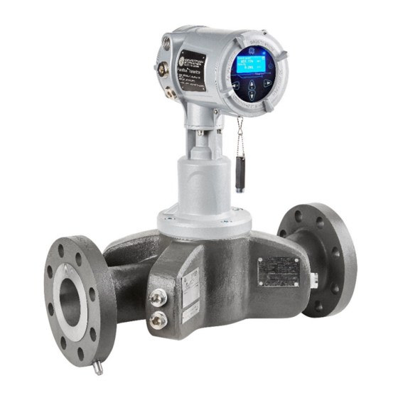
Baker Hughes Panametrics PanaFlow Z3 User Manual (118 pages)
Ultrasonic Flow Meter for Liquid Custody Transfer Measurement
Brand:
Baker Hughes
| Category:
Measuring Instruments
| Size: 10 MB
Table of Contents
Table of Contents
5
Chapter 1. Introduction
13
Overview
13
Theory of Operation
14
Transit-Time Flow Measurement
14
System Components
14
Local Transmitter Configuration
14
Remote Transmitter Configuration
15
Marking and Labeling
16
Model Tag Plate
16
Specification Tag Plate
17
Part String and Serial Number Tag Plate
18
Chapter 2. Installation
19
Installation Guidelines
19
Unpacking the Panaflow Z3 System
20
Inspection
20
Lifting the Panaflow Z3 System
20
Site Considerations
22
Installation Location
22
Straight Run Requirements
22
Transducer Location and Orientation
22
Inner Diameter Matching
23
Vibration Considerations
23
Guidelines for Installing Pipe Insulation
23
Fluid Comments
23
Making Electrical Connections
23
Local Mount Configuration Transducer Wiring
24
Remote Mount Configuration Transducer Wiring
24
Chapter 3. Programming
27
Introduction
27
HMI Features
27
Indicator Lights
28
Passcodes
28
Unlock from Keypad Lockout
28
Measurement View, Log-In and Primary
28
Measurement View
28
Changing Display Format
29
Selecting a Composite Measurement to Display
29
Selecting a Channel Measurement to Display
30
Totalizer Display
31
Log-In and Primary
33
System Settings
33
Selecting Units
34
Supported Unit Groups and Units
34
Meter Settings
35
Inputs and Outputs
36
Modbus Port Settings
36
Standard Analog Output
37
Setting up Analog Output
37
Understanding the Error Handling Option
37
Calibrating Analog Output
39
Standard Digital Output
40
Setting up Pulse Output
40
3.5.3.2 Setting up Frequency Output
42
3.5.3.3 Understanding the Error Handling Option
43
3.5.3.4 Setting up Alarm Output
45
Option Comm Slot-1 (Optional)
47
Option Slot-1 Configured as HART
47
3.5.4.2 Option Slot-1 Configured as FF
47
Option I/O Slot-2 (Optional)
48
Option IO (Slot2): Setting up Analog Output
48
3.5.5.2 Option IO (Slot2): Calibrating Analog Output
49
3.5.5.3 Option IO (Slot2): Setting up Analog Input
50
3.5.5.4 Option IO (Slot2): Calibrating Analog Input
51
3.5.5.5 Option IO (Slot2): Calibrating RTD Input
52
Programming Menu Options
53
Programming the Pipe
53
Programming the Fluid
53
Programming the Path Configuration
55
Programming the Flow and Diagnostic Limits
55
Programming Advanced Settings
56
Software Upgrade
56
Perform Software Upgrade
57
Chapter 4. Error Codes and Troubleshooting
59
Introduction
59
Error Classification and Error Codes
59
Flow Errors (E-Errors)
59
General Guidelines for Troubleshooting Flow Errors with Error Codes
59
Single Channel Error
59
Multi-Channel Error
60
Viewing Channel Specific Error/Warnings
60
Viewing Flow Diagnostics
60
Fluid and Pipe Problems
64
Fluid Problems
64
Pipe Problems
64
Transducer/Buffer Problems
65
Wetted Transducer Problems
65
Service Test Points
66
System Errors (S-Errors)
67
Communication Errors (C-Errors)
69
Transmitter Errors
70
4.10 Option I/O Errors
71
4.11 Meter Health with Diagnostics Data
72
Chapter 5. Maintenance and Service
75
Hardware Maintenance and Inspection
75
Servicing the Pipe Interface
76
Servicing the Sensor Ports or Transmitter Interface
76
Required Equipment
76
Instructions to Relieve Pressure in the Sensor Port or Transmitter Interface
76
Instructions to Rotate the XMT1000 Transmitter
78
Removing the XMT1000 Transmitter
79
Service
80
Spare Parts
80
Installing Replacement Parts
80
Appendix A. Specifications and Model Configurations
81
Operation and Performance
81
Meter Body/Transducer
82
Transmitter
83
Serial Number Information
85
Pressure Derating Information
88
O-Ring Chemical Compatibility
90
Appendix B. Data Records
99
Electronics
99
Data Entry
99
Initial Settings
100
Diagnostic Parameters
103
Appendix C. Modbus Map
105
Input Registers Map
105
Appendix D. CE Mark Compliance
107
Introduction
107
Wiring
107
Warranty
109
Advertisement
Advertisement
Related Products
Baker Hughes PanaFlow Z1G
Baker Hughes PanaFlow Z2G
Baker Hughes Panametrics PanaFlow LC
Baker Hughes 022-508-909
Baker Hughes Bently Nevada Ranger Pro
Baker Hughes Druck DPI104
Baker Hughes Druck DPI104-IS
Baker Hughes Druck DPI705E
Baker Hughes Druck DPI705E-IS
Baker Hughes Druck Dry TC 165
Baker Hughes Categories
Control Unit
Measuring Instruments
Valve Positioners
Test Equipment
Controller
More Baker Hughes Manuals
Login
Sign In
OR
Sign in with Facebook
Sign in with Google
Upload manual
Upload from disk
Upload from URL