Table of Contents
Advertisement
Quick Links
Advertisement
Table of Contents

Related Manuals for Baker Hughes Panametrics dew.IQ


Summary of Contents for Baker Hughes Panametrics dew.IQ
- Page 1 dew.IQ Moisture analyzer User’s manual 910-295 Rev. C...
- Page 3 dew.iQ Moisture analyzer User’s manual 910-295 Rev. C October 2017...
- Page 4 [no content intended for this page]...
-
Page 5: Table Of Contents
Contents Chapter 1. Features and capabilities Introduction ..................1 Electronics . - Page 6 3.4.4 Selecting an alarm type ................48 3.4.5 How the alarm types work .
- Page 7 5.6 Reading and setting the calibration references ..........77 5.6.1 Setting the calibration high reference .
-
Page 8: Chapter 1. Features And Capabilities
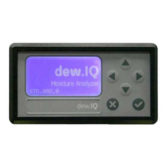
Chapter 1. Features and capabilities Introduction Electronics The dew.IQ is a single-channel hygrometer that measures You can program the meter using the keys on the front panel (see Figure 1 below). The dew.IQ universal power supply moisture content in gases. It is suitable for a wide range of process conditions in applications that require real-time accepts voltages from 100 to 240 VAC, or you may order the moisture measurement. -
Page 9: Probes
Probes The moisture probe is the part of the system that comes in direct contact with the process. The dew.IQ uses any Panametrics M Series probe (see Figure 2 below) or an IQ.probe (see Figure 3 below) to measure dew point temperature in °c or 0 F. -
Page 10: Chapter 2. Installation
Chapter 2. Installation Introduction WARNING! To ensure safe operation, the dew.IQ must be Installing the dew.IQ includes the following steps : installed and operated as described in this • Selecting the analog recorder output (see page 4) manual. Also, be sure to follow all applicable local safety codes and regulations for •... -
Page 11: Selecting The Analog Recorder Output
2.2 Selecting the analog recorder output Note: By default, the analog recorder output is set to the Make sure the dew.IQ is turned OFF and unplugged. current output. For wall mount and bench mount units, remove the dew.IQ from its enclosure before proceeding (see the Note: Customers must provide their own cable for appropriate figures in Appendix A). - Page 12 2.2 Selecting the analog recorder output (cont.) Remove the screw at the top of the back panel (see Figure 4 below). Figure 4: Back Panel (AC cord version shown) Lift the back edge of the top cover (see Figure 5 below). Figure 5: Lifting the Back Edge of the Cover...
- Page 13 2.2 Selecting the analog recorder output (cont.) Slide the cover toward the back of the dew.IQ (see Figure 6 below). Figure 6: Sliding the Cover to the Rear Lift the cover away from the enclosure (see Figure 7 below). Figure 7: Removing the Cover...
- Page 14 2.2 Selecting the analog recorder output (cont.) Locate switch S1 (see the highlighted area in Figure 8 below). CAUTION! Use proper ESD grounding prior to setting the switch. Set switch S1 to the desired position: V for voltage or I for current. Figure 8: Switch S1 on the Main PC Board After setting the switch, reinstall the cover and secure it with the rear enclosure screw.
-
Page 15: Mounting The Electronics
2.3 Mounting the electronics 2.3.1 Panel mount The dew.IQ is available in the following configurations: • “Panel Mount” on page 8 The panel mount unit can be installed in a panel up to 0.25 in. (6 mm) thick. See Figure 43 on page 100, for the required •... - Page 16 2.3.1 Panel Mount (cont.) To mount the dew.IQ in a panel with a 3.69”(94 mm) x 1.81” (46 mm) opening, refer to the figures and complete the following steps : Remove the side panel mount label prior to installation. Figure 9: Removing Side Panel Mount Label Slide the gasket along the dew.IQ and place it around the back of the display (see Figure 10 below).
- Page 17 2.3.1 Panel mount (cont.) Slide the dew.IQ into the panel cutout (see Figure 11 below). Figure 11: Sliding the dew.IQ into the Panel Cutout Behind the panel, insert the mounting brackets into the side holes provided (see Figure 12 below). Figure 12: Installing the Mounting Brackets...
- Page 18 2.3.1 Panel mount (cont.) Hold the chassis and lock each mounting bracket in place by sliding it toward the rear of the dew.IQ (see Figure 13 below). Figure 13: Locking the Mounting Brackets in Place Use a screwdriver to extend the bracket screws to the back of the panel and secure the dew.IQ in the panel cutout (see Figure 14 below).
-
Page 19: Rack Mount
2.3.1 Panel mount (cont.) Using a feeler gauge behind the display, check the gasket compression , and tighten the bracket screws until the gap is 0.028” (0.71 mm)± 0.002” (0.05 mm), as shown in see Figure 15 below. Figure 15: Checking the Gasket Compression 2.3.2 Rack mount The rack mount dew.IQ is a half-rack sized component designed for mounting in a standard instrument rack. -
Page 20: Bench Mount
2.3.3 Bench mount The bench mount dew.IQ can be placed on any clean, flat , horizontal surface that provides adequate clearance around the unit for proper operation and configuration. See Figure 44 on page 101, for the dimensions. -
Page 21: Wall Mount
2.3.4 Wall mount The wall mount dew.IQ consists of a panel mount unit pre-installed in a standard Type 4X, IP66 wall mount enclosure. See Figure 39 on page 96, Figure 40 on page 97 and Figure 41 on page 98 for dimensions and installation notes. The enclosure should be mounted on a vertical surface that provides adequate clearance for proper operation and configuration by completing the following steps: Loosen the four (4) screws on the front of the enclosure, pull the door straight forward until it stops and then swing the... -
Page 22: Mounting The Sample System
2.4 Mounting the sample system The sample system is normally fastened to a flat metal plate that has four mounting holes. Upon request , Panametrics can also provide the sample system in an enclosure. A typical sample system is shown in Figure 16 below. Figure 16: Typical Sample System... -
Page 23: Installing The Probe
2.4 Mounting the sample system 2.5 Installing the probe (cont.) The following probes are available for use with the dew.IQ • M Series probe (see Figure 2 on page 2) Complete the following steps to mount the sample system: • IQ.probe (see Figure 3 on page 2) Fasten the sample system plate or enclosure to a vertical wall or panel with a bolt in each of the four... - Page 24 2.5 Installing the probe (cont.) Refer to Figure 17 below, and complete these steps to install the probe in the sample cell: Insert the probe into the sample cell and thread the probe into the sample cell fitting. Make sure you do not cross the threads.
-
Page 25: Wiring The System
2.6 Wiring the system Wiring the dew.IQ system includes the following steps: WARNING! • Connecting the probe (see page 21 or page 24) For wall mount units, refer to Figure 41 on • Connecting the analog recorder output (see page 27) page 98 for the service loop required on all cable connections. - Page 26 2.6 Wiring the system (cont.) Figure 18: Electrical Connections (AC Power Cord Units) Note: Figure 18 above, Figure 19 below and Figure 20 on page 20 show the three different power connections available for the dew.IQ. Be sure to use the figure that corresponds to your unit. All other electrical connections are identical for the three versions.
- Page 27 2.6 Wiring the system (cont.) CAUTION! This symbol in Figure 20 below indicates the presence of electrical shock hazards. Always de-energize the meter prior to connecting or disconnecting the AC power wires to avoid electrical shock. Figure 20: Electrical Connections (AC Power Terminal Units)
-
Page 28: Connecting An M Series Probe
2.6.1 Connecting an M series probe The M Series probe must be connected to the dew.IQ with a continuous run of Panametrics two-wire shielded cable. When connecting the probe, protect the cable from excessive strain (bending, pulling, etc.) and avoid subjecting the cable to temperatures above 6S°C (1 49°F) or below -S0°C (-S8°F). - Page 29 2.6.1 Connecting an M series probe (cont.) IMPORTANT: To maintain good contact at the terminal block and to avoid damaging the pins on the wiring connector, pull the connector straight off (not at an angle) the terminal block, and make the cable connections while the connector is off the unit. After the wiring is complete, push the connector straight onto the terminal block (not at an angle).
- Page 30 2.6.1 Connecting an M series probe (cont.) Figure 24: Making Probe Cable Connections to the Connector Reinsert the connector into the lower terminal block on the rear of the dew.IQ (see Figure 25 below). Figure 25: Reinserting the Connector into the Terminal Block...
-
Page 31: Connecting An Iq.probe
2.6.2 Connecting an IQ.probe Complete the following steps to wire an IQ.probe to the dew.IQ Insert the end of probe cable (see Figure 26 below) with the connector onto the probe and twist the connector head clockwise until it is secure. IMPORTANT: Ensure that the power is OFF before proceeding . - Page 32 2.6.2 Connecting an IQ.probe (cont.) IMPORTANT: To maintain good contact at the terminal block and to avoid damaging the pins on the wiring connector, pull the connector straight off (not at an angle) the terminal block, and make the cable connections while the connector is off the unit. After the wiring is complete, push the connector straight onto the terminal block (not at an angle).
- Page 33 2.6.2 Connecting an IQ.probe (cont.) Figure 28: Wiring the Cable to the Connector Reinsert the connector into the lower terminal block on the rear of the dew.IQ (see Figure 29 below). Figure 29: Reinserting the Connector into the Terminal Block Note: If there is a No Link error for the IQ.probe, check the wiring connections and make sure there is no short between +15V and RTN.
-
Page 34: Connecting The Analog Output
2.6.3 Connecting the analog output IMPORTANT: Ensure that the power is OFF before proceeding. Refer to Table 2 below to connect your analog recorder to pins 14 and 15 on the lower terminal block on the back of the dew.IQ (see Figure 22 on page 22 or Figure 27 on page 25). - Page 35 2.6.4.1 Connecting the high/low alarms (A and 8) IMPORTANT: Ensure that the power is OFF before proceeding. Each of these alarms can be set to trip on either a high or low condition. For a high alarm, the alarm will trip if the input exceeds the setpoint.
- Page 36 2.6.4.2 Connecting the fault alarm If enabled, the dew.IQ fault alarm trips when one or more of the following faults occurs: power failure, range error (configurable) or watchdog function system reset Note: The watchdog function is a supervisory circuit that automatically resets the unit whenever a system error occurs. The fault alarm has two possible operating modes: •...
-
Page 37: Connecting The Input Power
2.6.5 Connecting the input power There are three input power configurations available for the dew.IQ • AC power cord (not used for wall mount units) • DC power terminals (available for all configurations) • AC power terminals (available for all configurations) Proceed to the appropriate section to connect your input power. - Page 38 2.6.5.1 Connecting the AC power cord (cont.) Figure 32: The AC Power Cable Installed 2.6.5.2 Connecting the DC power terminals The DC power cable (with 14 to 26 AWG conductors) is supplied by the customer. To connect the power cable to the dew.IQ input power terminals (see Figure 19 on page 19) complete the following steps: Remove the input power connector from the rear panel of the dew.IQ (see Figure 33 below).
- Page 39 2.6.5.2 Connecting the DC power terminals {cont.) Strip the three power cable conductors by about 3/8” (10 mm). Insert each wire into the appropriate connector pin (see Table 4 below) and tighten each screw to secure the wires in place. Wire Color Function Black...
- Page 40 2.6.5.3 Connecting the AC power terminals IMPORTANT: Unlike the DC power connector, which has screw terminals, the AC power connector has spring finger terminals. It is essential that this connector be removed from the dew.IQ for wiring to avoid putting stress on the PCB, which may cause damage to the board.
- Page 41 2.6.5.3 Connecting the AC power terminals (cont.) Strip the three power cable conductors by about 3/8” (10 mm). Using a small screwdriver to assist in opening each spring finger terminal, insert each wire into the appropriate connector pin (see Table 5 below). Wire Color Function Black...
-
Page 42: Chapter 3. Initial Setup And Operation
Chapter 3. Initial setup and operation Using the dew.IQ The front panel components perform the following functions: • Display - The programming menus and options are All programming of the dew.IQ is done via the front panel shown on the LCD display screen. keypad and display, as illustrated below. -
Page 43: Starting Up
3.1.1 Starting up 3.1.2 Accessing the menus After installation, the dew.IQ moisture analyzer can After unlocking the menu (as confirmed by the absence be configured to meet the user’s requirements . While of the padlock icon in the lower right corner), press Cancel programming the instrument, refer to one of the following to display the Main Menu (see Figure 36 below). -
Page 44: Entering Numeric Values
3.1.3 Entering numeric values The dew.IQ has no numeric keypad. Numeric values are entered using a “combination lock” entry (see Figure 37 below as an example): Use the left and right arrow keys to select the digit to change. The digit selected will be indicated with an Use the up and down arrow keys to increment or... -
Page 45: Setting Up The Display
3.2 Setting up the display When the screen is unlocked, press the Cancel key and the Main Menu appears with several options. To set up the display, select Display... and press Enter following screen appears: 3.2.1 Selecting the primary units To select the units for the primary display, select Unit Select and press Enter . -
Page 46: Setting The Decimal Places
3.2.2 Setting the decimal places To set the decimal places for unit values, from the Display Menu use the arrow keys to select Decimal and press Enter . The following screen appears: Note: The decimal places setting determines the number of digits displayed to the right of the decimal point (“.”)for the value, if possible. -
Page 47: Setting Up The Analog Output
3.3 Setting up the analog output 3.3.1 Entering the output menu To set up the output, from the Main Menu choose Output... and press Enter . The following screen appears: 3.3.2 Selecting the output units From the Output Menu, select Units and press Enter . -
Page 48: Selecting An Output Type
3.3.3 Selecting an output type IMPORTANT: Before changing the analog output type, refer to “Selecting the Analog Recorder Output” on page 4 to make sure that Switch S1 is set correctly (V for voltage or I for current). To change the output type, from the Output Menu select Type and press Enter . -
Page 49: Changing The Output Zero
3.3.5 Changing the output zero To adjust the output zero, from the Output Menu select Lower and press Enter . A screen similar to the following appears: Use the left and right arrow keys to select each digit to be changed and the up and down arrow keys to increase or decrease its value. -
Page 50: Testing The Output
3.3.6 Testing the output To verify proper operation of connected recording or SCADA equipment, the dew.IQ can output test signals of known value. Based on the percent of range selected, the Test Menu causes the dew.IQ to output test signals that can be easily calculated. As examples, the test signals for three commonly used range percentages are shown in Table 6 below. -
Page 51: Trimming The Output
3.3.7 Trimming the output The Trim Menu enables the operator to compensate for differences in the 0/4-20 mA or 0-2V dew.IQ test outputs and the readings on a connected output device. To trim the analog output: Select Trim from the Output Menu and press Enter . - Page 52 3.3.7 Trimming the output (cont.) Enter the value read from the connected equipment as the Zero Trim value, as follows: Note: Since you cannot trim O mA or O V for negative offsets, trim for the lower end of the scale is always at the 4 mA or 0.4 V output.
-
Page 53: Setting Up The Measurement Alarms
3.3.7 Trimming the output (cont.) Example: Trim is reset, then Trim Zero is selected. The connected output device reports 3.977 mA. The operator enters “3.977” as the Zero Trim value. Trim Span is selected. The connected output device reports 19.985 mA. The operator enters “19.985”... -
Page 54: Selecting The Alarm Status
3.4.2 Selecting the alarm status To select the alarm status, from the Alarm Menu select Status and press Enter . The following screen appears: Use the arrow keys to select OFF or ON and press Enter . The display returns to the Alarm Menu. -
Page 55: Selecting An Alarm Type
3.4.4 Selecting an alarm type To change the alarm type, from the Alarm Menu select Type and press Enter . A screen similar to the following appears: Use the arrow keys to select an alarm type (see “How the Alarm Types Work” on page 49). Press Enter to save (or Cancel to keep the previous value), and return to the Alarm Menu. -
Page 56: How The Alarm Types Work
3.4.5 How the alarm types work The available alarm types (see Figure 38 below) for the dew.IQ are: • Setpoint: The alarm activates when the selected parameter exceeds the upper limit. It deactivates when the selected parameter is less than the lower limit. •... -
Page 57: Setting The Alarm Span
3.4.6 Setting the alarm span To adjust the alarm span, from the Alarm Menu select Upper and press Enter . A screen similar to the following appears: Use the left and right arrow keys to select each digit to be changed and the up and down arrow keys to increase or decrease its value. -
Page 58: Testing The Alarm Relays
3.4.8 Testing the alarm relays To test the alarm relay and devices connected to it, from the Alarm Menu select Test and press Enter . A screen similar to the following appears: Use the left and right arrow keys to select Reset or Trip and press Enter . -
Page 59: Viewing System Information
3.5 Viewing system information To view the dew.IQ system information, from the Main Menu choose About... and press Enter Proceed to the following sections. Note: The information in the following screens are examples only. Your dew.IQ will display the information for your specific unit. -
Page 60: Checking The Status
3.5.2 Checking the status To check the status of the MicroSD card, from the About dew.IQ menu select Status and press Enter . A screen similar to the following appears: The information includes the format, amount of used space and amount of free space for an installed SD card. -
Page 61: Checking The Probe
3.5.4 Checking the probe Note: The information in the following screens is a typical example only. Your unit always displays your actual information. To check the probe details, from the About dew. IQ menu select Probe and press Enter screen similar to one of the following appears: For an M Series probe, this probe information is shown. -
Page 62: Checking The Wiring
3.5.5 Checking the wiring To view the dew.IQ wiring diagram, from the About dew.IQ menu select Wiring and press Enter . A screen similar to the following appears: When you are ready to return to the dew.IQ Main menu, press Cancel twice. - Page 63 [no content intended for this page]...
-
Page 64: Chapter 4. Data Logging
Chapter 4. Data logging Checking the data log Status To check the data log status, from the Logging Menu select Status and press Enter . A screen similar to the following appears: The current data log status is displayed. After about 10 seconds or upon pressing Enter (whichever occurs first), the screen returns to the Logging Menu. - Page 65 4.3 Setting the log units (cont.) Use the arrow keys to select the unit to log, and press Enter . The following screen appears: To change the unit sett ing, select Modify and press Enter . The following screen appears: Use the arrow keys to select the first unit to be logged and press Enter .
-
Page 66: Setting The Log Interval
4.4 Setting the log interval To set the log interval , from the Set Log Params menu, select Interval and press Enter . The following screen appears: Use the left and right arrow keys to select each digit to be changed and the up and down arrow keys to increase or decrease its value. -
Page 67: Setting The Log Status Flags
4.6 Setting the log status flags The flags used to identify the log status are as follows: • Range Err • Over Range • Under Range • No Comm • No Link • Bad CRC • Bad Message • Auto Cal •... -
Page 68: Managing Log Files
4.7 Managing log files To manage the log file status, from the Logging Menu select Manage and press Enter . If no log has been created, the following screen appears: 4.7.1 Creating a new log Note: The New Log option is available only if there are no logs currently running or paused. All running or paused logs must be closed before proceeding. -
Page 69: Pausing Or Closing A Log
4.7.2 Pausing or closing a log After a new log is created, it can be paused or closed at any time. To pause or close a log, from the Manage Log Files menu select Pause/Close and press Enter . The following screen appears: The log file name is shown in the header. -
Page 70: Resuming A Log
4.7.3 Resuming a log A paused log can be resumed or closed at any time. To resume or close a log, from the Manage Log Files menu select Resume/Close and press Enter . The following screen appears: Select Resume or Close and press Enter . -
Page 71: Deleting Log Files
4.7.5 Deleting log files To erase existing log files, from the Manage Log Files menu, select Erase Log and press Enter The File Listing screen appears: Using the arrow keys, move to the name of the log file to be deleted and press Enter . -
Page 72: Ejecting The Microsd Card
4.8 Ejecting the MicroSD card Ejecting the MicroSD card requires two steps: Closing all active logs. Complete this step by following the instructions in “Pausing or Closing a Log” on page 62. Ejecting the MicroSD card. Accomplish this as follows: IMPORTANT: Physically removing the MicroSD card from the dew.IQ without first closing all active logs and ejecting the card will not damage either the card or the dew.IQ, but it may result in data loss. -
Page 73: Viewing Data Log Files
4.9 Viewing data log files Any standard MicroSD card reader may be used to read the dew.IQ MicroSD card on a PC. The log files are stored in text format , and any word processing or spreadsheet program may be used to read the data. See “Reading the MicroSD Card “... -
Page 74: Chapter 5. Programming The Settings Menu
Chapter 5. Programming the settings menu Entering your passcode To access the Settings Menu, proceed as follows: To access the Settings menu, from the Main Menu select Settings... and press Enter The Settings Menu is the only user menu that requires a passcode. The passcode is a four-digit number that enables only authorized users to enter setup data. -
Page 75: Setting The Fault Alarm
5.2 Setting the fault alarm Note: Access to this menu requires a passcode (see “Entering Your Passcode” on page 67 ). To configure the fault alarm, from the Settings Menu select Fault Alarm and press Enter Then, enter your passcode and press Enter 5.2.1 Setting the fault alarm status To check the status of the fault alarm, from the Fault Alarm menu, select Status and press Enter . -
Page 76: Setting The Fault Alarm Type
5.2.2 Setting the fault alarm type Note: For more information on alarm types, see “How the Alarm Types Work” on page 49. To check or change the fault alarm type,select Type and press Enter . The following screen appears: To change the type of fault alarm used, select the non-highlighted option and press Enter The screen returns to the Fault, Alarm menu. -
Page 77: Setting The Fault Alarm Options
5.2.4 Testing the fault alarm To test the Fault Alarm, select Test and press Enter . The following screen appears: To reset the fault alarm, select Reset and press Enter . To trip the fault alarm, select Trip and press Enter . - Page 78 5.3 Setting AutoCal (cont.) Use the left and right arrow keys to select each digit to be changed and the up and down arrow keys to increase or decrease its value. Press Enter to save the new value (or Cancel keep the previous value), and return to the AutoCal Settings menu.
-
Page 79: Entering Calibration Data For An M Series Probe
5.4 Entering calibration data for an M Series probe Note: Access to this menu requires a passcode (see “Entering Your Passcode” on page 67 ). Note: If you are using an IQ.probe, see “Viewing Calibration Data for an IQ.probe” on page 75. To enter M Series probe calibration data, from the Settings Menu select Cal Data and press Enter . -
Page 80: Selecting The Calibration Point
5.4.2 Selecting the calibration point To select the calibration point, highlight Select Cal Point and press Enter . The following screen appears: Use the left and right arrow keys to select each digit to be changed and the up and down arrow keys to increase or decrease its value. -
Page 81: Entering The Dew Point Calibration
5.4.4 Entering the dew point calibration To enter the dew point calibration value for the selected point, highlight Edit DP/°C and press Enter . The following screen appears: Use the left and right arrow keys to select each digit to be changed and the up and down arrow keys to increase or decrease its value. -
Page 82: Viewing Calibration Data For An Iq.probe
5.5 Viewing calibration data for an IQ.probe Note: Access to this menu requires a passcode (see “Entering Your Passcode” on page 67). Note: If you are using an M Series probe , see “Entering Calibration Data for an M Series Probe” on page 72. To view the IQ.probe calibration data, from the Settings Menu select Cal Data and press Enter . -
Page 83: Reading The Fh Value
5.5.2 Reading the FH value To view the FH calibration value for the selected point, highlight Read FH and press Enter . The following screen appears: The FH value is for viewing only. When you are ready, press Cancel to return to the Read FH/ DP Calibration menu. -
Page 84: Reading And Setting The Calibration References
5.6 Reading and setting the calibration references Note: This section applies only to an M Series probe. The Cal Reference menu is not available for an IQ.probe Note: Access to this menu requires a passcode (see “Entering Your Passcode” on page 67 ). IMPORTANT: The dew.IQ is factory programmed with high and low reference MH values. -
Page 85: Setting The Calibration High Reference
5.6.1 Setting the calibration high reference To update the high reference setting, from the Edit Cal Refs menu select High Reference and press Enter . A screen similar to the following appears : Use the left and right arrow keys to select each digit to be changed and the up and down arrow keys to increase or decrease its value. -
Page 86: Entering An M Series Probe Serial Number
5.7 Entering an M Series probe serial number Note: This section applies only to an M Series probe. The Probe SN menu is not available for an IQ.probe Note: Access to this menu requires a passcode (see “Entering Your Passcode” on page 67 ). To update the probe serial number, from the Settings Menu select Cal Data and press Enter Then, enter your passcode and press Enter . -
Page 87: Setting The Volume Mixing Ratio
5.8 Setting the volume mixing ratio Note: Access to this menu requires a passcode (see “Entering Your Passcode” on page 67 ). To set the volume mixing ratio, from the Settings Menu select VN Ratio and press Enter . Then, enter your passcode and press Enter . -
Page 88: Setting The Pressure Value
5.8.2 Setting the pressure value To set the pressure value, select Press. Value and press Enter . The following screen appears: Use the left and right arrow keys to select each digit to be changed and the up and down arrow keys to increase or decrease its value. -
Page 89: Setting The System Clock
5.9 Setting the system clock Note: Access to this menu does not require a passcode. To set the system clock, from the Settings Menu select Clock and press Enter to display the current day, date and time. To make changes, see the following sections. 5.9.1 Setting the hour To change the hour, select Hour and press Enter . -
Page 90: Setting The Minutes
5.9.2 Setting the minutes To change the minutes, select Minutes and press Enter . The following screen appears: Use the left and right arrow keys to select each digit to be changed and the up and down arrow keys to increase or decrease its value. Press Enter to save the new value (or Cancel keep the previous value) and return to the previous menu. -
Page 91: Setting The Date
5.9.4 Setting the date To change the date, select Date and press Enter . The following screen appears: Use the left and right arrow keys to select each digit to be changed and the up and down arrow keys to increase or decrease its value. Press Enter to save the new value (or Cancel keep the previous value) and return to the previous menu. -
Page 92: Selecting The Probe Type
5.10 Selecting the probe type Note: Access to this menu requires a passcode (see “Entering Your Passcode” on page 67 ). IMPORTANT: Changing the probe type will reset the analog output, measurement alarms, fault alarm and output range to their factory default settings. -
Page 93: Setting The Constant Dp °C Offset
5.11 Setting a constant DP °C offset Note: Access to this menu does not require a passcode. This feature enables the user to add a constant DP °C offset to all dew.IQ readings. It allows for positive or negative offset limiting up to ±S0°C. -
Page 94: Chapter 6. Service And Maintenance
Chapter 6. Service and maintenance Introduction 6.2 The service menu The dew.IQ is designed to be maintenance and trouble The dew.IQ Service menu is intended for use only by trained free. However, because of severe process conditions and service engineers and requires the use of a Factory-Level other factors, minor problems may occur from time to time. -
Page 95: Troubleshooting Common Problems
6.3 Troubleshooting common problems If the dew.IQ measurements read too wet or too dry, or if they do not make sense, there may be a problem with a process component of the probe. See Table 7 below to trouble shoot and solve such problems. Possible cause Response and action Symptom: The accuracy of the moisture sensor is questioned... -
Page 96: Replacing/Recalibrating Moisture Probes
6.4 Replacing/recalibrating moisture probes For maximum accuracy, moisture probes should be IMPORTANT: returned to the factory for recalibration every 6-12 months, To maintain good contact at the terminal block and to depending on the application. Under very severe conditions, avoid damaging the pins on the wiring connector, pull the more frequent calibrations are recommended However, connector straight off (not at an angle) the terminal block. -
Page 97: Cleaning The Dew.iq Front Panel
6.5 Cleaning the dew.IQ front panel When necessary, use the procedure below to clean the front panel of the dew.IQ. You will need the following items : • Clean, lint-free cloth • Cleaning solution (soap and warm water) To clean the front panel, complete the following steps: Moisten the cloth with the cleaning solution. -
Page 98: Chapter 7. Specifications
Chapter 7. Specifications Electronics Intrinsic Safety Switch-Selectable Output Ranges External safety barrier for moisture input (optional on M 0-2 V, 10 kn minimum load resistance Series probe) 0-20 mA, 400 n maximum series resistance 4-20 mA, 400 n European Compliance maximum series resistance See the EU Declaration of Conformity at the downloads page The outputs are user-programmable within the range of the... - Page 99 Electronics (cont.) Alarm Setpoint Repeatability Temperature ±0.2°F (±0.1°C) dew point Operating: -20° to 60°C (-4° to 140°F) Datalogger Storage: -40° to 70°C (-40° to 158°F) 32 GB capacity with MicroSD card, 4 GB MicroSD card Warm-Up Time included Meets specified accuracy within three minutes Display Configurations 128 x 64 matrix LCD...
-
Page 100: Moisture Measurement
7.2 Moisture measurement Sensor Type Calibrated Accuracy at 77°F (25°C) Thin-film aluminum oxide ±2°C (±3.6°F) from -65° to l0°C (-85° to 50°F) Moisture Probe Compatibility ±3°C (±5.4°F) from -80° to -66°C (- 112° to -87°F) Compatible with all Panametrics M-Series aluminum oxide Repeatability moisture probes and the IQ.probe ±0.5°C (±0 .9°F) from -65°... - Page 101 [no content intended for this page]...
-
Page 102: Appendix A. Outline And Installation Drawings
Appendix A. Outline and installation drawings This appendix includes the following dew.IQ drawings: • “Wall Mount Outline & Installation (ref. dwg. 712-1823, 1 of 3)” on page 96 • “Wall Mount Outline & Installation (ref. dwg. 712-1823, 2 of 3)” on page 97 •... -
Page 103: Wall Mount Outline & Installation (Ref. Dwg. 712-1823, 1 Of 3)
Figure 39: Wall Mount Outline and Installation (ref. dwg. 712-1823, 1 of 3) -
Page 104: Wall Mount Outline & Installation (Ref. Dwg. 712-1823, 2 Of 3)
Figure 40: Wall Mount Outline & Installation (ref. dwg. 712-1823, 2 of 3) -
Page 105: Wall Mount Outline & Installation (Ref. Dwg. 712-1823, 3 Of 3)
Figure 41: Wall Mount Outline & Installation (ref. dwg. 712-1823, 3 of 3) -
Page 106: Rack Mount Outline & Installation (Ref. Dwg. 712-1824)
Figure 42: Rack Mount Outline & Installation (ref. dwg. 712-1824) -
Page 107: Panel Mount Outline & Installation ( Ref. Dwg. 712-1825)
Figure 43: Panel Mount Outline & Installation (ref. dwg. 712-1825) -
Page 108: Bench Top Outline & Installation (Ref. Dwg. 712-1826)
Figure 44: Bench Top Outline & Installation (ref. dwg. 712-1826) -
Page 109: Interconnection Diagram (Ref. Dwg. 702-1381)
Figure 45: Interconnection Diagram (ref. dwg. 702-1381) -
Page 110: Appendix B. Menu Maps
Appendix B. Menu maps This appendix includes the following dew.IQ menu maps: • “Main Menu Map Using M Series Probe” on page 104 • “Main Menu Map Using IQ.probe” on page 105... - Page 111 FIgure 46: Main Menu Map Using M Series Probe...
- Page 112 FIgure 47: Main Menu Map Using IQ.probe...
- Page 113 [no content intended for this page]...
-
Page 114: Appendix C. Reading The Microsd Card
Appendix C. Reading the MicroSD card C.1 Removing the MicroSD card IMPORTANT: Before physically removing the MicroSD Card, refer to “Ejecting the MicroSD Card” on page 65. Locate the memory card in the lower center of the rear panel of the dew.IQ and pull the left side of the flexible cover. The cover is hinged on the right side (see Figure 48 and Figure 49 below). - Page 115 C.1 Removing the MicroSD card (cont.) Push in the memory card until it clicks and then release it (see Figure 50 below). Figure 50: Pushing in on the MicroSD Card After the MicroSD card is partially ejected, pull it from the dew.IQ chassis (see Figure 51 below). Figure 51: Removing the MicroSD Card...
-
Page 116: Connecting The Microsd Card To A Pc
C.2 Connecting the MicroSD card to a PC Plug the MicroSD card into a card reader (see Figure 52 below) Figure 52: Plugging the MicroSD Card into a Card Reader Connect the card reader to a PC (see Figure 53 below). Figure 53: Plugging the Card Reader into a PC... -
Page 117: Accessing The Log Files
C.3 Accessing the log files From the PC, open My Computer and find the card reader in the “Devices with Removable Storage” section. (see Figure 54 below). Figure 54: Locating the Card Reader... - Page 118 C.3 Accessing the log files (cont.) Click on the Removable Disk icon and a window similar to Figure 55 below opens. The available log files are listed in the window. Figure 55: List of Log Files Click on the desired log file and a window similar to Figure 56 below opens. The data in the log file is listed in the window. Figure 56: Log File Data...
- Page 119 C.3 Accessing the log files (cont.) The dew.IQ log files can be opened with a spreadsheet program, such as Microsoft Excel. Launch the spreadsheet program and select Open (see Figure 57 below). Figure 57: Opening a Log File in Microsoft Excel Click on the name of the desired log file (see Figure 58 below).
-
Page 120: Setting Up A Log File
C.4 Setting up a log file Make sure that the file type is set to ‘½II Types” and then open the selected log file by double clicking on the file name. A window similar to the one in Figure 59 below will open. Figure 59: Microsoft Excel Import Wizard - Step 1... - Page 121 C.4 Setting Up a log file (cont.) Follow the directions on the screen, make changes if necessary, and then click on Next. A window similar to the one in Figure 60 below will open. Figure 60: Microsoft Excel Import Wizard - Step 2...
- Page 122 C.4 Setting Up a log file (cont.) Select the desired data delimiters, and click on Next >. A window similar to the one in Figure 61 below will open. Select each column and set the desired data format for that column (see Figure 61 below). Figure 61: Microsoft Excel Import Wizard - Step 3...
- Page 123 C.4 Setting Up a log file (cont.) When the setup is complete, click on Finish, and a window similar to Figure 62 below will open . The log file is now properly formatted for graphing or analysis, and the results may be saved as a standard spreadsheet file for future use. Figure 62: Successful Log File Import...
- Page 124 Index About Menu ..........52 Bench Mount, Installation .
- Page 125 Fault Alarm M Series Probe Description ..........29 Entering Clibration Data .
- Page 126 Panel Mount Sample Cell Gasket ........... 9 Description .
- Page 127 Volume Mixing Ratio, Setting ....... .80 Wall Mount, Installation ........14 Warm-Up Time .
-
Page 128: Default Factory Passcode
Default factory passcode Your passcode is 2719 Please remove this page and put it in a safe place for future reference. - Page 129 [no content intended for this page]...
- Page 130 Tel: +1 800 833 9438 (toll-free) E-mail: mstechsupport@bhge.com Tel: +1 978 437 1000 E-mail: mstechsupport@bhge.com Panametrics, a Baker Hughes Business, provides solutions in the toughest applications and environments for moisture, oxygen, liquid and gas flow measurement. Experts in flare management, Panametrics technology also reduces flare emissions and optimizes performance.
Need help?
Do you have a question about the Panametrics dew.IQ and is the answer not in the manual?
Questions and answers