
Related Manuals for Baker Hughes Panametrics MTS6


Summary of Contents for Baker Hughes Panametrics MTS6
- Page 1 Process Analyzers Moisture Target™ Series 6 User’s Manual 910-291 E panametrics.com October 2021...
- Page 3 October 2021 panametrics.com Copyright 2021 Baker Hughes company. This material contains one or more registered trademarks of Baker Hughes Company and its subsidiaries in one or more countries. All third-party product and company names are trademarks of their respective holders.
- Page 4 [no content intended for this page]...
- Page 5 Preface Information Paragraphs • Note paragraphs provide information that provides a deeper understanding of the situation, but is not essential to the proper completion of the instructions. • Important paragraphs provide information that emphasizes instructions that are essential to proper setup of the equipment.
- Page 6 Environmental Compliance Waste Electrical and Electronic Equipment (WEEE) Directive Baker Hughes is an active participant in Europe’s Waste Electrical and Electronic Equipment (WEEE) take-back initiative, directive 2002/96/EC. The equipment that you bought has required the extraction and use of natural resources for its production. It may contain hazardous substances that could impact health and the environment.
-
Page 7: Table Of Contents
Contents Chapter 1. Features and Capabilities Introduction ..................... .1 Electronics Unit . - Page 8 Contents Setting Other Information ..................54 3.6.1 Entering the Passcode .
-
Page 9: Chapter 1. Features And Capabilities
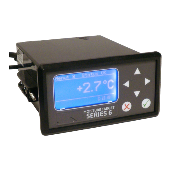
Chapter 1. Features and Capabilities Chapter 1. Features and Capabilities Introduction The Moisture Target Series 6 (MTS6) is a microprocessor-based, single-channel hygrometer that measures moisture content in gases. It is intended for Original Equipment Manufacturer (OEM) applications, and is suitable for a wide range of process conditions that require real-time moisture measurement. -
Page 10: Probes
Chapter 1. Features and Capabilities Probes The moisture probe is the part of the system that comes in direct contact with the process. The MTS6 uses any Panametrics M Series (see Figure 2) or a VeriDri probe (see Figure 3) to measure dew point temperature in °C or °F. The sensor assembly is secured to the probe mount and is protected with a sintered stainless steel shield (see Figure 2). -
Page 11: Chapter 2. Installation
Chapter 2. Installation Chapter 2. Installation Introduction Installing the MTS6 includes the following steps: • selecting the recorder output • mounting the electronics unit • mounting the sample system • installing the probe into the sample system • wiring the input power wiring the probe and alarm connections •... -
Page 12: Selecting The Recorder Output
Chapter 2. Installation Selecting the Recorder Output Note: By default, the recorder is set to the current output. Note: The customer will provide their own cable for connecting the recorder. Acceptable cables range from 16 to 26AWG. The MTS6 has one isolated analog recorder output. The recorder output provides either a current or voltage signal, which is set by switch S1 on the main PC board. - Page 13 Chapter 2. Installation Figure 6: Sliding the Cover Back Figure 7: Lifting the Cover Locate switch S1 (see Figure 8, highlighted area). CAUTION! Use proper ESD grounding prior to changing the switch. Set switch S1 to the desired position: V for voltage or I for current. Moisture Target Series 6 User’s Manual...
- Page 14 Chapter 2. Installation Figure 8: Switch S1 on the Main PC Board After setting the switch, replace the cover and reinsert the rear enclosure screw. Moisture Target Series 6 User’s Manual...
-
Page 15: Mounting The Electronics Unit
Chapter 2. Installation Mounting the Electronics Unit The MTS6 unit can be installed in a panel up to 0.25 in. (6 mm) thick. See Appendix A, Outline and Installation Drawings, for the required panel cutout dimensions. IMPORTANT: For NEMA 4 and IP66 installation, the MTS6 must be mounted in a rigid, flat panel using the panel gasket and both mounting brackets provided. - Page 16 Chapter 2. Installation Figure 11: Sliding the MTS6 into the Panel Cutout Behind the panel, insert the mounting brackets into the side holes provided (see Figure 12). Figure 12: Installing the Mounting Brackets Hold the chassis and lock each mounting bracket in place by sliding it toward the rear of the MTS6 (see Figure 13). Figure 13: Locking the Mounting Brackets in Place Moisture Target Series 6 User’s Manual...
-
Page 17: Adapter Plate Mounting
Chapter 2. Installation Use a screwdriver to extend the bracket screws to the back of the panel and secure the MTS6 in the panel cutout (see Figure 14). Figure 14: Securing the MTS6 to the Panel Using a feeler gauge behind the gasket, check the compression, and tighten the bracket screws until the gap is 0.028”... - Page 18 Chapter 2. Installation Figure 16: Installing the Adapter Plate Gasket Fit the adapter plate into the panel cutout (see Figure 17). Figure 17: Inserting the Adapter Plate Behind the panel, place the metal backing plate over the four adapter plate mounting screws (see Figure 18). Figure 18: Applying the Backing Plate Moisture Target Series 6 User’s Manual...
- Page 19 Chapter 2. Installation Apply nuts to the four screws and secure the assembly to the panel (see Figure 19 and Figure 20). Use a feeler gauge behind the gasket, check the compression, and tighten the nuts until the gap is 0.032” ±0.002”. Figure 19: Securing the Assembly to the Panel Figure 20: Plate Assembly Mounting Complete Now mount the MTS6 using steps 1-6 in Basic Mounting on page 7.
-
Page 20: Mounting The Sample System
Chapter 2. Installation Figure 22: MTS6 Installation with Adapter Plate - Front Mounting the Sample System Figure 23: Typical Sample System Moisture Target Series 6 User’s Manual... -
Page 21: Installing The Probe
Chapter 2. Installation The sample system is normally fastened to a flat metal plate that has four mounting holes. Upon request, Panametrics can also provide the sample system in an enclosure. Complete the following steps to mount the sample system: Fasten the sample system plate or enclosure to a vertical wall or panel with a bolt in each of the four corners. -
Page 22: Wiring The System
Chapter 2. Installation Wiring the System Wiring the MTS6 system includes the following steps: • connecting the probe • connecting the recorder output • connecting the alarms • installing the power cable WARNING! To ensure safe operation, the MTS6 must be installed and operated as described in this manual. Also, be sure to follow all applicable local safety codes and regulations for installing electrical equipment. - Page 23 Chapter 2. Installation Figure 27: MTS6 Wiring Diagram Moisture Target Series 6 User’s Manual...
-
Page 24: Connecting A Standard Probe
Chapter 2. Installation 2.6.1 Connecting a Standard Probe The probe must be connected to the MTS6 with a continuous run of Panametrics two-wire shielded cable. When connecting the probe, protect the cable from excessive strain (bending, pulling, etc.) and avoid subjecting the cable to temperatures above 65°C (149°F) or below –50°C (–58°F). - Page 25 Chapter 2. Installation Figure 30: Bottom Connector Removed Figure 31: Making Probe Cable Connections to the Connector Figure 32: Reinserting the Connector into the Terminal Block Moisture Target Series 6 User’s Manual...
-
Page 26: Connecting A Veridri Probe
Chapter 2. Installation 2.6.2 Connecting a VeriDri Probe Use the following steps to wire the VeriDri to the MTS6. Figure 33: Four-Wire, VeriDri Probe Cable Insert the end of probe cable with the connector onto the probe and twist the connector head clockwise until it is secure. - Page 27 Chapter 2. Installation Figure 34: Bottom Connector Removed Figure 35: Wiring the Cable to the Connector Figure 36: Reinserting the Connector into the Terminal Block Note: When there is a No Link error for the VeriDri, check the wiring to ensure proper connections and make sure there is no short between the +15V and RTN.
-
Page 28: Connecting The Recorder Outputs
Chapter 2. Installation 2.6.3 Connecting the Recorder Outputs IMPORTANT: Ensure that the power is off before proceeding. Connect your recorder to the lower terminal block on the back of the MTS6 (pins 14 and 15), as shown in Figure 25 and Figure 26 on page 14. -
Page 29: Installing The Ac Power Cable
Chapter 2. Installation 2.6.4.2 Connecting the Fault Alarm If enabled, the fault alarm trips when one or more of the following faults occurs: • power failure • range error (configurable) • watchdog function system reset Note: The watchdog function is a supervisory circuit that automatically resets the unit whenever a system error occurs. -
Page 30: Installing The Dc Power Cable
Chapter 2. Installation Figure 39: The AC Power Cable Installed 2.6.6 Installing the DC Power Cable The DC power cable (with 14 to 26 AWG wires) is supplied by the customer. Use the following instructions to connect the cable to the MTS6. Figure 40: MTS6 Rear Panel Connections - DC Version Remove the DC Connector from the rear panel (see Figure 41). - Page 31 Chapter 2. Installation Figure 41: Removing the DC Connector Strip each conductor of the DC power cable by approximately 3/8”. Insert each wire into the appropriate slot (+, – and chassis) and tighten each screw to secure them in place. IMPORTANT: Ensure that the chassis ground connection is properly grounded.
- Page 32 Chapter 2. Installation Moisture Target Series 6 User’s Manual...
-
Page 33: Chapter 3. Operation And Programming
Chapter 3. Operation and Programming Chapter 3. Operation and Programming Using the MTS6 3.1.1 Starting Up After proper installation, the MTS6 Transmitter can be set up to accommodate the user’s requirements. Typically, the user may need to configure the analog outputs, trim the analog outputs, and program logging. Refer to a Menu Map, Figure 49 on page 94 when using an M Series probe, or Figure 50 on page 95 when using a VeriDri probe, and complete the following steps. -
Page 34: Entering Numeric Values
Chapter 3. Operation and Programming 3.1.3 Entering Numeric Values Since the MTS6 has no numeric keypad, numeric values are entered using a “combination lock” style of entry: Use the left and right arrow keys to select the digit to change. The digit selected will be indicated with a Use the up and down arrow keys to increment or decrement the digit. -
Page 35: Setting Up The Display
Chapter 3. Operation and Programming Setting Up the Display When the screen is unlocked, touch the Cancel key and the Main Menu appears with several options. To set up the display, select Display... and press Enter . The following screen appears: 3.2.1 Selecting Primary Units... -
Page 36: Setting Decimal Places
Chapter 3. Operation and Programming 3.2.2 Setting Decimal Places To set the decimal places for unit values, from the Display Menu use the arrow keys to select Decimal and press Enter . The following screen appears. The decimal places setting determines the number of digits displayed for the value to the right of the decimal symbol (“.”), if possible. -
Page 37: Setting Up The Output
Chapter 3. Operation and Programming Setting Up the Output 3.3.1 Entering the Output Menu To set up the output, from the Main Menu choose Output... and press Enter . The following screen appears. 3.3.2 Selecting Output Units Output Menu From the Output Menu, select Units and press Enter . -
Page 38: Selecting An Output Type
Chapter 3. Operation and Programming 3.3.3 Selecting an Output Type Note: Before changing the output type, refer to Section 2.2 Selecting the Recorder Output on page 4 to make sure that Switch S1 is at the correct setting (V for voltage or I for current). ... -
Page 39: Changing The Lower Output Span
Chapter 3. Operation and Programming 3.3.5 Changing the Lower Output Span To adjust the lower output span, from the Output Menu select Lower and press Output Menu . A screen similar to the following appears. Enter Test Units Type Trim... -
Page 40: Setting Up Alarms
Chapter 3. Operation and Programming Use the left or right arrow keys to select YES and press Enter . This cancels any previous trim values, and returns the MTS6 to its factory adjustment. The display returns to the previous screen. ... -
Page 41: Selecting Alarm Status
Chapter 3. Operation and Programming Use the arrow keys to select the output Alarm Menu [A] (A or B) to be set up and press Enter . The display returns to the Alarm Menu. Select Alarm: =Accept =Cancel 3.4.2 Selecting Alarm Status ... -
Page 42: Selecting Alarm Units
Chapter 3. Operation and Programming 3.4.3 Selecting Alarm Units To select alarm units, from the Alarm Menu select Units and press Enter Use the arrow keys to select a unit. Press Enter to save (or Cancel to keep the previous value), and return to the Alarm Menu. -
Page 43: How The Alarm Types Work
Chapter 3. Operation and Programming 3.4.5 How the Alarm Types Work Trip Upper Hysteresis Setpoint Lower Reset Reset Trip In Band Trip Reset Trip Reset Out Band Reset Trip Figure 45: Example of Alarm Types Moisture Target Series 6 User’s Manual... -
Page 44: Changing The Upper Alarm Span
Chapter 3. Operation and Programming 3.4.6 Changing the Upper Alarm Span To adjust the upper alarm span, from the Alarm Menu select Upper and press . A screen similar to the following appears. Enter Use the left and right arrow keys to select each digit to be changed and the up and ... -
Page 45: Testing The Alarm Relays
Chapter 3. Operation and Programming 3.4.8 Testing the Alarm Relays To test the alarm relay, and devices connected to it, from the Alarm Menu select Test and press Enter . A screen similar to the following appears. Use the left and right arrow keys to select Reset or Trip and press Enter . -
Page 46: Log Settings Menu
Chapter 3. Operation and Programming 3.5.2 Log Settings Menu Note: To access the Settings... option under the Logging Menu, the log file must be stopped (see Starting/Stopping Log Files on page 40. 3.5.2.1 Setting Log Units From the Logging Menu select Settings... and press Enter . - Page 47 Chapter 3. Operation and Programming 3.5.2.3 Setting a Field Separator To designate a mark to separate the log fields, from the Set Log Params menu select FieldSep and press Enter . The following screen appears. Use the arrow keys to select the mark used to separate the log fields and press Enter ...
-
Page 48: Managing Log Files
Chapter 3. Operation and Programming 3.5.3 Managing Log Files To manage the log file status, from the Logging Menu select Manage and press Enter . If no log has been created, the following screen appears. 3.5.3.1 Creating a New Log Note: In order for the new log option to be available, there can be no log running or paused. - Page 49 Chapter 3. Operation and Programming 3.5.3.2 Pausing a Log When a new log is created, it can be paused or closed. To pause the log, from the Manage Log Files menu select Pause/Close and press Enter . The following screen appears.
-
Page 50: Ejecting The Sd Card
Chapter 3. Operation and Programming 3.5.3.5 Deleting Log Files To erase an existing log file(s), from the Manage Log Files menu, select Erase Log and press Enter . The File Listing screen appears. Using the arrow keys, move to the listing to be deleted, and press Enter . -
Page 51: Setting Other Information
Chapter 3. Operation and Programming Setting Other Information Main Menu To change other settings, from the Main Menu select Settings... and press Enter . The following screen appears. Display... Settings... Output... Service... Alarm... About... Logs... LOCK 3.6.1 Entering the Passcode The Settings Menu is the only menu that requires a passcode. - Page 52 Chapter 3. Operation and Programming To change the type of fault relay, select the other option and press Enter . The screen returns to the Fault Alarm menu. 3.6.2.3 Setting Fault Alarm Options To view the status other options select Options and press Enter .
-
Page 53: Setting Autocal
Chapter 3. Operation and Programming 3.6.3 Setting Autocal Note: To enter the Autocal Settings menu, you must be using a standard M Series probe. If a VeriDri probe is being used, AutoCal is not necessary and will not be accessible. ... - Page 54 Chapter 3. Operation and Programming Use the left and right arrow keys to select each digit to be changed and the up and User Passcode: down arrow keys to increase or decrease its value. Once the passcode has been entered, press Enter and the following screen appears.
- Page 55 Chapter 3. Operation and Programming 3.6.4.3 Setting the MH Calibration To set up the MH calibration, highlight Edit MH and press Enter . The following screen appears. Use the left and right arrow keys to select each digit to be changed and the up and ...
-
Page 56: Setting Calibration Data 2
Chapter 3. Operation and Programming 3.6.5 Setting Calibration Data 2 Note: If you are using a VeriDri probe, the following steps will apply. For a standard M Series probe, see Setting Calibration Data 1 on page 45. To view calibration data, from the Settings Menu select Cal Data and press Enter . - Page 57 Chapter 3. Operation and Programming The FH value is for viewing only. When you are ready, press Cancel to return to the Read FH/DP Calibration menu. 3.6.5.3 Reading the DP Value To view the DP value, highlight Read DP Value and press Enter .
-
Page 58: Reading And Setting The Calibration References
Chapter 3. Operation and Programming 3.6.6 Reading and Setting the Calibration References Note: The following procedure applies only if an M Series probe is being used. If a VeriDri probe is used, Cal Reference... is not accessible. IMPORTANT: The MTS6 is factory programmed with high and low reference MH values. These values are generated from a factory lab calibration and should not be changed without first consulting Panametrics technical support. - Page 59 Chapter 3. Operation and Programming 3.6.6.1 Setting the Calibration High Reference To update high reference settings, from the Edit Cal Refs menu select High Reference and press Enter . A screen similar to the following appears. Use the left and right arrow keys to select each digit to be changed and the up and down arrow keys to increase or decrease its value.
-
Page 60: Entering The M Series Probe Serial Number
Chapter 3. Operation and Programming 3.6.7 Entering the M Series Probe Serial Number Note: The following procedure applies only if an M Series probe is being used. If a VeriDri probe is used, Probe SN is not accessible. To update the probe serial number, from the Settings Menu select Cal Data and press Settings Menu ... -
Page 61: Setting The Volume Mixing Ratio
Chapter 3. Operation and Programming 3.6.8 Setting the Volume Mixing Ratio Note: Setting the Volume Mixing Ratio is an optional feature, available only if the ppmv software version was purchased. Note:To set the volume mixing ratio, from the Settings Menu select V/V Ratio and press Settings Menu ... - Page 62 Chapter 3. Operation and Programming 3.6.8.2 Setting the Pressure Value To set the pressure value, select Press. Value and press Enter . The following screen appears. Use the left and right arrow keys to select each digit to be changed and the up and ...
-
Page 63: Resetting The Time
Chapter 3. Operation and Programming 3.6.9 Resetting the Time Settings Menu To reset the time, from the Settings Menu select Clock and press Enter . The current time appears on the following screen. Clock... Fault Alm... AutoCal... Probes Cal Data... DpC Offset V/V Ratio... - Page 64 Chapter 3. Operation and Programming 3.6.9.2 Setting the Minutes To change the minutes, select Minutes and press Enter . The following screen appears. Use the left and right arrow keys to select each digit to be changed and the up and ...
-
Page 65: 3.6.10 Selecting The Probe Type
Chapter 3. Operation and Programming Use the left and right arrow keys to select each digit to be changed. Use the up and down arrow keys to change the value. When finished, press Enter and return to the previous menu, then press Cancel to return to the Settings Menu. -
Page 66: Setting A Constant Dp °C Offset
Chapter 3. Operation and Programming 3.6.11 Setting a Constant DP °C Offset This feature enables the customer to add a constant DP °C offset to their reading. It allows for positive or negative offset limiting to +/- 50°C. It works only within the calibrated range of the sensor. Alarms A & B are based on the offset value, and likewise, they will work only within the calibrated range of the sensor. -
Page 67: Viewing System Information
Chapter 3. Operation and Programming Viewing System Information 3.7.1 Checking the ID To check identification information, from the Main Menu, select About and press Enter Main Menu The following screen appears. Settings... Display... Output... Service... About... Alarm... Logs... LOCK ... -
Page 68: Checking The Probe
Chapter 3. Operation and Programming 3.7.4 Checking the Probe To check the probe details, from the About menu select Probe and press Enter screen similar to one of the following appears. Data when using an M Series probe. To return to the About MTS6 menu, press Cancel ... -
Page 69: Checking The Wiring
Chapter 3. Operation and Programming 3.7.5 Checking the Wiring To view the MTS6 wiring diagram, from the About menu select Wiring and press . A screen similar to the following appears. Enter To return to the Main Menu, press Cancel twice. - Page 70 Chapter 3. Operation and Programming Your passcode is 2719. Please remove this page and put it in a safe place for future reference. Moisture Target Series 6 User’s Manual...
-
Page 71: Chapter 4. Service And Maintenance
Chapter 4. Service and Maintenance Chapter 4. Service and Maintenance Introduction The MTS 6 is designed to be maintenance and trouble free. However, because of severe process conditions and other factors, minor problems may occur from time to time. Some of the most common problems and recommended maintenance procedures are discussed in this chapter. -
Page 72: Replacing/Recalibrating Moisture Probes
Chapter 4. Service and Maintenance Table 3: Troubleshooting Guide for Common Problems Possible Cause Response and Action Symptom: The accuracy of the moisture sensor is questioned. Response: Reads too wet during dry down There is insufficient time for the system conditions or too dry in wet up conditions. - Page 73 Chapter 4. Service and Maintenance Moisture Target Series 6 User’s Manual...
-
Page 74: Cleaning The Mts6 Front Panel
Chapter 4. Service and Maintenance Cleaning the MTS6 Front Panel When necessary, use the procedure below to clean the front panel. You will need the following: • Clean, lint free cloth • Cleaning solution (soap and warm water) To clean the front panel: Moisten the cloth with the cleaning solution. -
Page 75: Chapter 5. Specifications
Chapter 5. Specifications Chapter 5. Specifications Electronics Input: moisture signal from Panametrics thin-film aluminum oxide moisture sensor on an M Series probe or a VeriDri probe Intrinsic Safety: external safety barrier for moisture input (optional) Analog Output: single, isolated recorder output for dew point, internally optically isolated, 10-bit (0.1%) resolution 0–2 V: 10 kminimum load resistance 0–20 mA: 400 ... -
Page 76: Moisture Measurement
Chapter 5. Specifications Input Power: option 1, AC: universal power 100-240 VAC @ 50-60 Hz option 2, DC: 24 VDC nominal ±10% Power Dissipation: AC units: 5 W maximum DC units: 5 W maximum Temperature: operating: –20° to +60°C storage: –40° to +70°C Warm-Up Time: meets specified accuracy within three minutes Dimensions:... - Page 77 Chapter 5. Specifications Accuracy: ±2°C from –65° to 60°C ±3°C from –110° to -66°C Repeatability: ±0.5°C from –65° to 60°C ±1.0°C from –110° to -66°C Moisture Target Series 6 User’s Manual...
- Page 78 Chapter 5. Specifications Moisture Target Series 6 User’s Manual...
- Page 79 Chapter A. Outline and Installation Drawings Chapter A. Outline and Installation Drawings Moisture Target Series 6 Hygrometer User’s Manual71...
- Page 80 Chapter A. Outline and Installation Drawings Figure 46: MTS6 Outline and Mounting (ref. dwg #712-1550) 72Moisture Target Series 6 Hygrometer User’s Manual...
- Page 81 Chapter A. Outline and Installation Drawings Figure 47: MTS6 Optional Adapter Plates (ref. dwg #705-1297) Moisture Target Series 6 Hygrometer User’s Manual73...
- Page 82 Chapter A. Outline and Installation Drawings Figure 48: Interconnection Diagram (ref. dwg #702-1015) 74Moisture Target Series 6 Hygrometer User’s Manual...
- Page 83 Chapter B. Menu Maps Chapter B. Menu Maps Moisture Target Series 6 Hygrometer User’s Manual93...
- Page 84 Chapter B. Menu Maps Figure 49: Main Menu Map Using M Series Probe 94Moisture Target Series 6 Hygrometer User’s Manual...
- Page 85 Chapter B. Menu Maps Figure 50: Main Menu Map Using VeriDri Probe Moisture Target Series 6 Hygrometer User’s Manual95...
- Page 86 Chapter B. Menu Maps [no content intended for this page 96Moisture Target Series 6 Hygrometer User’s Manual...
- Page 87 Chapter C. Reading the MicroSD Card Chapter C. Reading the MicroSD Card Removing the Card IMPORTANT: Before removing the MicroSD Card, refer to section 3.5.4 Ejecting the SD Card on page 42, to first stop the data log. Locate the memory card in the lower center of the rear panel and pull the flexible cover from the left.
- Page 88 Chapter C. Reading the MicroSD Card Push in the memory card until it clicks and pull it from the MTS6 chassis (see Figure 53 and Figure 54). Figure 53: Pushing in on the MicroSD Card Figure 54: Removing the MicroSD Card 98Moisture Target Series 6 Hygrometer User’s Manual...
- Page 89 Chapter C. Reading the MicroSD Card Plug the memory card into a card reader and insert the reader into a computer (see Figure 55 and Figure 56). Figure 55: Plugging the Reader into a PC Figure 56: The Reader Plugged In Moisture Target Series 6 Hygrometer User’s Manual99...
- Page 90 Chapter C. Reading the MicroSD Card Accessing the Files From the PC, open My Computer and find the device (see Figure 57). Figure 57: Locating the Device Click on Removable Disk and a screen similar to Figure 58 on page 101 appears.
- Page 91 Chapter C. Reading the MicroSD Card Figure 58: List of Log Files Click on the desired file and a screen similar to Figure 59 appears. Figure 59: Log File Notepad Moisture Target Series 6 Hygrometer User’s Manual101...
- Page 92 Chapter C. Reading the MicroSD Card Log files can be opened with a text editor. Open Excel and select Open. Figure 60: Importing Log Files to Excel Figure 61: Selecting the Log File to Open 102Moisture Target Series 6 Hygrometer User’s Manual...
- Page 93 Chapter C. Reading the MicroSD Card Setting Up the Files Open the file by clicking twice on the number. Note: Ensure that the file type equals all types. The following screen appears (see Figure 62). Figure 62: Excel Import Wizard 1 Follow the directions on the screen, make changes if necessary, and click on Next >.
- Page 94 Chapter C. Reading the MicroSD Card Figure 63: Excel Import Wizard 2 Set the desired data delimiters, and click on Next >. The following screen appears (see Figure 64 on page 105). 104Moisture Target Series 6 Hygrometer User’s Manual...
- Page 95 Chapter C. Reading the MicroSD Card Figure 64: Excel Import Wizard 3 Select each column and set the data format for it (see Figure 64). When the setup is complete, click on Finish, and a screen similar to Figure 65 on page 106 appears. Moisture Target Series 6 Hygrometer User’s Manual105...
- Page 96 Chapter C. Reading the MicroSD Card Figure 65: Successful Excel Import The log file is now properly formatted for graphing or analysis. 106Moisture Target Series 6 Hygrometer User’s Manual...
- Page 97 Chapter D. The Non-Enclosure MTS6 Package Caution! Risk of electric shock. 1. Mount the MTS6 package in an enclosed panel where no hazardous live wires are exposed. See Figure 49 for dimensions. 139.6 (5.50) 149.8 (5.90) 48 (1.89) 119.6 (4.71) 55.6 (2.19) 129.6 (5.10) Note:...
- Page 98 Moisture Target Series 6 User’s Manual...
- Page 99 Index Adapter Plate Gasket ........... . . 9 Gasket .
- Page 100 Index Output Starting Up ..........33 Changing the Lower Span .
- Page 101 Warranty Warranty Each instrument manufactured by Panametrics is warranted to be free from defects in material and workmanship. Liability under this warranty is limited to restoring the instrument to normal operation or replacing the instrument, at the sole discretion of Panametrics . Fuses and batteries are specifically excluded from any liability.
- Page 102 Warranty Return Policy If a Panametrics instrument malfunctions within the warranty period, the following procedure must be completed: Notify Panametrics , giving full details of the problem, and provide the model number and serial number of the instrument. If the nature of the problem indicates the need for factory service, Panametrics will issue a RETURN AUTHORIZATION NUMBER (RAN), and shipping instructions for the return of the instrument to a service center will be provided.
- Page 103 Warranty Panametrics 1100 Technology Park Drive Billerica, MA 01821 declare under our sole responsibility that the Moisture Target™ Series 6 Hygrometer to which this declaration relates, is in conformity with the following standards: • EN 61326-1: 2006, Class A, Table 2, Industrial Locations •...
- Page 104 Warranty [no content intended for this page] Moisture Target Series 6 User’s Manual...
- Page 106 E-mail: mstechsupport@bakerhughes.com Copyright 2021 Baker Hughes company. This material contains one or more registered trademarks of Baker Hughes Company and its subsidiaries in one or more countries. All third-party product and company names are trademarks of their respective holders. 910-219 E...
Need help?
Do you have a question about the Panametrics MTS6 and is the answer not in the manual?
Questions and answers