Table of Contents
Advertisement
Quick Links
Advertisement
Table of Contents

Related Manuals for Baker Hughes Panametrics Aurora TransPort


Summary of Contents for Baker Hughes Panametrics Aurora TransPort
- Page 1 Aurora TransPort BH004C11 EN C panametrics.com...
- Page 3 May 2023 panametrics.com Copyright 2023 Baker Hughes company. This material contains one or more registered trademarks of Baker Hughes Company and its subsidiaries in one or more countries. All third-party product and company names are trademarks of their respective holders.
- Page 4 [no content intended for this page]...
- Page 5 Preface Services Panametrics provides customers with an experienced staff of customer support personnel ready to respond to technical inquiries, as well as other remote and on-site support needs. To complement our broad portfolio of industry-leading solutions, we offer several types of flexible and scalable support services including: Training, Product Repairs, Service Agreements and more.
- Page 6 Preface Auxiliary Equipment Local Safety Standards The user must make sure that he operates all auxiliary equipment in accordance with local codes, standards, regulations, or laws applicable to safety. Working Area WARNING! Auxiliary equipment may have both manual and automatic modes of operation. As equipment can move suddenly and without warning, do not enter the work cell of this equipment during automatic operation, and do not enter the work envelope of this equipment during manual operation.
- Page 7 Preface Environmental Compliance RoHS The Aurora TransPort fully complies with RoHS regulations. Waste Electrical and Electronic Equipment (WEEE) Directive Waste Electrical and Electronic Equipment Panametrics is an active participant in Europe’s (WEEE) take-back initiative, directive 2012/19/EU. The equipment that you bought has required the extraction and use of natural resources for its production. It may contain hazardous substances that could impact health and the environment.
- Page 8 Preface [no content intended for this page] Aurora TransPort User’s Manual...
-
Page 9: Table Of Contents
Contents Chapter 1. Features and Capabilities Overview ......................1 Important Use Limitations . - Page 10 Contents Chapter 4. Programming Advanced Features Comm Port Settings ................... . 27 4.1.1 Selecting a Comm Port .
- Page 11 Contents Working with Trend Plots, Trend Tabular Data and Scan Plots ..........68 Chapter 6.
- Page 12 Contents [no content intended for this page] viii Aurora TransPort User’s Manual...
-
Page 13: Chapter 1. Features And Capabilities
Chapter 1. Features and Capabilities Overview Panametrics’s Aurora TransPort moisture analyzer makes it possible for natural gas processing and transportation facilities to spot check moisture content in real-time with high precision and reliability. The analyzer system is designed to continuously monitor moisture content in an extracted sample of process gas using tunable diode laser absorption spectroscopy (TDLAS). -
Page 14: Features
Chapter 1. Features and Capabilities Features • Rugged, light weight design [<50lbs] with telescoping handle with large inline wheels for easy deployment across flat surfaces. Also provided are 3 heavy duty lift handles for loading and unloading into motor vehicles. •... - Page 15 Chapter 1. Features and Capabilities Figure 1: Laser Absorption Cell, Basic Elements Aurora TransPort is capable of providing moisture measurements in a variety of units. The partial pressure of water, multiplied by 10 and divided by the total sample pressure, yields the volume ratio in ppmv (parts per million by volume).
-
Page 16: Sample System Components
Chapter 1. Features and Capabilities Sample System Components The Aurora TransPort sample system is a compact design providing the functionality for measurement of sample pressure, temperature, and flow conditions. Manual control valves are provided for adjusting sample and bypass flow rates, as well as analyzer isolation during transport. Figure 2: Aurora TransPort Integral Gas Sample System Schematic A pressure relief valve, set to relieve at 30psig, is provided to prevent accidental over pressurization of the sample system, causing equipment damage or personnel injury. -
Page 17: Tdlas Measurement Specifications
Chapter 1. Features and Capabilities TDLAS Measurement Specifications Calibrated Range: 0 to 1000 ppmv Calibrated Accuracy: ±2 ppmV or ±1% of reading, whichever is greater (NIST or equivalent NMI traceable certification) Reading Repeatability: ±0.2 ppmv or ±0.1%, whichever is greater (CO2 applications: ±1.0 ppmv or ±0.5%, whichever is greater) Lower Detection Level: 2 ppmV (CO2 applications: 20 ppmV) - Page 18 Chapter 1. Features and Capabilities [no content intended for this page] Aurora TransPort User’s Manual...
-
Page 19: Chapter 2. Installation
Chapter 2. Installation Introduction The Aurora TransPort analyzer provides direct indication of moisture concentration in natural gas as well as other applications in refineries, heat treating furnaces, etc. Temperature and pressure sensors are used to provide high precision enhancement. It is designed to operate safe areas only as it does not have any hazardous area certification. -
Page 20: Making Electrical Connections
Chapter 2. Installation Making Electrical Connections The Aurora TransPort has remote data logging capability using AuroraView software by one of two serial communication modes. Figure 3: Aurora TransPort I/O cable connections Ethernet Mode (Recommended): Only one connection port and one top-panel jack is provided and labeled "Ethernet". It is the simplest serial communications connection to make and will meet the needs of most users. -
Page 21: Charging The Battery
Chapter 2. Installation The Aurora Transport has three channels of programmable analog (4-20mA) measurement output capability. Each channel can be assigned to any measurement parameter and precisely scaled to the users input range requirements. For connection use the Aurora Transport remote accessory cable (Panametrics# 130M5430). This cable is not supplied with the analyzer. -
Page 22: Monitoring Battery Status
Chapter 2. Installation Monitoring Battery Status The Aurora TransPort continuously monitors the state of charge of the battery. A battery charge indicator is provided in the upper left of the data display: • A solid filled indicator represents a full charge •... -
Page 23: Chapter 3. Operation And General Programming
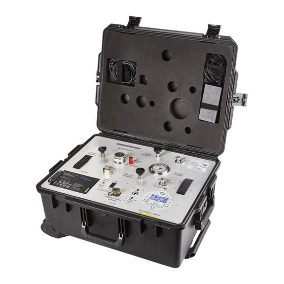
Sample System Refer to Figure 4 below to locate components referenced in the startup guide. Figure 4: Front Panel of Panametrics Aurora TransPort 3.2.1 Aurora TransPort Startup Ensure the Pelican transport case (13) is lying flat and horizontal on a stable surface before opening the cover. -
Page 24: Aurora Transport Shut Down
Chapter 3. Operation and General Programming Before powering up the unit, perform a coarse leak test of the sample system, preferably with clean, dry nitrogen/air supply. Please refer to Figure 2 for sample system schematic. Ensure that gas inlet pressure is < 30 psig with gas inlet (9), sample metering (6), and bypass metering (8) valves fully shut. -
Page 25: Keypad Features
Chapter 3. Operation and General Programming Keypad Features Power Indi- cator Menu Main Display Laser Fault Indicator Indicator Keypad Lock Information Indicator Indicator Enter Cancel Up, Left, Right, Down Arrows Figure 5: Aurora TransPort Keypad The Aurora TransPort has seven keys: a Menu key, four Arrow keys, a Cancel key, and an Enter key. -
Page 26: Indicator Lights
Chapter 3. Operation and General Programming 3.3.1 Indicator Lights If the Fault Indicator is lit, an instrument fault is detected. A message will be displayed in the Main Display, top/right. If the Information Indicator is lit, the instrument is still operating, but a message will appear in the Main Display top/right, with information about the instrument. -
Page 27: Accessing The Menus
Chapter 3. Operation and General Programming 3.3.4 Accessing the Menus After successfully unlocking the keypad, press the Menu key. The Aurora TransPort will display the Main Menu Figure 7 Menu Map Figure 17 on page 51 (see below). Use the arrow keys to highlight the menu item desired. Refer to Press Enter to select the highlighted item. -
Page 28: Starting Up
Chapter 3. Operation and General Programming 3.3.6 Starting Up TransPort After proper installation, the Aurora Transmitter can be set up to accommodate the user’s requirements. Typically, the user may need to configure the analog outputs, trim the analog outputs, and program the digital outputs. -
Page 29: Selecting Alt 1 And Alt 2 Units
Chapter 3. Operation and General Programming 3.4.2 Selecting Alt 1 and Alt 2 Units To set the units for Alt 1 and/or Alt 2, use the arrow keys to highlight the one to be set, and press Enter. The following screen appears: Use the arrow keys to highlight the desired unit type (Hygro, Temperature or Pressure) and press Enter. -
Page 30: Adjust
Chapter 3. Operation and General Programming 3.4.5 Adjust To modify the display contrast and brightness, from the Display Menu use the arrow keys to highlight Adjust and press Enter. The following screen appears. Use the Right/Left arrow keys to increase/decrease display contrast. Press Enter to save the changes, or press Cancel to return to the previous setup. -
Page 31: Selecting Output Units
Chapter 3. Operation and General Programming 3.5.2 Selecting Output Units To adjust the output units, from the Output Menu select Units and press Enter. A screen similar to the following appears. Use the arrow keys to select the unit type and press Enter. A screen similar to the following appears: Use the arrow keys to select a new unit. -
Page 32: Changing The Lower Output Span
Chapter 3. Operation and General Programming 3.5.5 Changing the Lower Output Span To adjust the lower output span, from the Output Menu select Lower and press Enter. A screen similar to the following appears. Use the left and right arrow keys to select each digit to be changed and the up and down arrow keys to increase or decrease its value. -
Page 33: Namur Filtering
Chapter 3. Operation and General Programming 3.5.7 NAMUR Filtering There may be situations where the NAMUR signaling behavior is undesirable (see Table 2 below). For example, a process operating at or near the Aurora TransPort calibration limits, or when connected to a SCADA or DCS system that cannot correctly distinguish between a measurement and an error signal. -
Page 34: Trimming The Outputs
Chapter 3. Operation and General Programming 3.5.9 Trimming the Outputs The Trim Menu enables the operator to compensate for differences in measurement of the 0/4-20 mA outputs by connected recorders or SCADA equipment. To trim the output: Select Trim from the Output Menu and press Enter. The following screen appears. Output Menu [Out A] The trim applies to whichever output is chosen with the Select menu item, and Note:... -
Page 35: Setting Up The Alarms
Chapter 3. Operation and General Programming Use the left and right arrow keys to select each digit to be changed, and the up and down arrow keys to increase or decrease its value. Press Enter to save (or Cancel to keep the previous value). -
Page 36: Selecting Alarm Units
Chapter 3. Operation and General Programming 3.6.3 Selecting Alarm Units To select alarm units, from the Alarm Menu select Units and press Enter. Use the arrow keys to select the unit type and press Enter. Temp was selected, this display appears. Use the arrow keys to select a unit. Press Alarm Menu Enter to save (or Cancel to keep the previous value), and return to the If Temperature was selected, this display appears. -
Page 37: How The Alarm Types Work
Chapter 3. Operation and General Programming 3.6.5 How the Alarm Types Work Figure 10 below for descriptions of the various alarm types: Figure 10: Example of Alarm Types 3.6.6 Changing the Upper Alarm Span To adjust the upper alarm span, from the Alarm Menu select Upper and press Enter. A screen similar to the following appears. -
Page 38: Changing The Lower Alarm Span
Chapter 3. Operation and General Programming 3.6.7 Changing the Lower Alarm Span To adjust the lower alarm span, from the Alarm Menu select Lower and press Enter. A screen similar to the following appears. Use the left and right arrow keys to select each digit to be changed and the up and down arrow keys to increase or decrease its value. -
Page 39: Chapter 4. Programming Advanced Features
Chapter 4. Programming Advanced Features Comm Port Settings To access the communication port settings, from the Main Menu select Settings and press Enter. The following screen appears: To access the communications port settings, select Comms... and press Enter. The following screen appears: 4.1.1 Selecting a Comm Port There are two physical comm ports in the Aurora TransPort. -
Page 40: Setting The Parity
Chapter 4. Programming Advanced Features 4.1.3 Setting the Parity To set parity, from the Comm Port Menu select Parity and press Enter. The following screen appears. Use the arrow keys to highlight the desired parity and press Enter. After a parity selection is made, the Aurora prompts for the number of stop bits. Use the arrow keys to highlight the desired number and press Enter. -
Page 41: Adjusting The Response Delay
Chapter 4. Programming Advanced Features 4.1.6 Adjusting the Response Delay Some Modbus masters may have limitations in their ability to receive a response immediately after transmitting the request. This can often occur when the RS-485 protocol is used, as the Master must change from transmit to receive operation. -
Page 42: Ethernet Settings
Chapter 4. Programming Advanced Features Type a character at the terminal. If the character is received correctly, the hexadecimal value of the character sent Figure 12 will be returned (see below). If the character is not returned, this is usually due to incorrect parity or stop-bit settings. -
Page 43: Connecting To An Ethernet Lan
Chapter 4. Programming Advanced Features 4.2.3 Connecting to an Ethernet LAN The Ethernet option supports the 10Base-T and 100Base-TX twisted-pair Ethernet standards. A waterproof RJ45 connector is provided for use with standard CAT5/CAT5e Ethernet cables. Use of Shielded Twisted Pair (STP) cable is recommended. -
Page 44: Device Discovery
Chapter 4. Programming Advanced Features 4.2.5 Device Discovery Advanced Device Discovery Protocol The Digi module used for Ethernet connectivity supports Digi's ADDP ( ). ADDP uses UDP port 2362 and a multicast IP address of 224.0.5.128. You will need to enable these on your firewall for the ADDP protocol to work for the device discovery utility. -
Page 45: Adjust Offset Values
Chapter 4. Programming Advanced Features Adjust Offset Values To adjust offset values, from the Settings Menu select Adjust... and press Enter. The following screen appears. 4.3.1 Adjusting the PPMv Offset To adjust the PPMv offset, select PPM Level and press Enter. The following screen appears. -
Page 46: Adjusting The Scan Averaging
Chapter 4. Programming Advanced Features 4.3.3 Adjusting the Scan Averaging To adjust the Scan Averaging, from the Filters Menu select Scan Avg and press Enter. The following screen appears: The Scan Average setting is used to change system noise rejection. By averaging entire scans, the Signal/Noise Ratio (SNR) can be increased. -
Page 47: Setting The Dew Point Calculation Method
Chapter 4. Programming Advanced Features 4.3.4 Setting the Dew Point Calculation Method • The dew point is the temperature at which the air is saturated with respect to water vapor over a liquid surface. • The frost point is the temperature at which the air is saturated with respect to water vapor over an ice surface. There can be a difference of several degrees C between the dew point and the frost point. -
Page 48: Saturation Calculation
Chapter 4. Programming Advanced Features 4.3.5 Saturation Calculation Gosudarstvenii Standart In certain regulatory zones, the (GOST) calculation of the Saturation pressure is required, and gives different results from ASTM and ISO methods. Select the calculation that is most appropriate for your application. -
Page 49: Set Up The Background Gas
Chapter 4. Programming Advanced Features Set Up the Background Gas 4.4.1 Selecting the Type of Gas The Aurora TransPort TDLAS is normally calibrated to a standard gas mixture that is representative of “typical” natural gas. The primary components and concentrations of this gas mixture are: Component Concentration Methane (CH4) -
Page 50: Setting The Z Factor
Chapter 4. Programming Advanced Features Unless otherwise requested, the Aurora TransPort is shipped from the factory configured for Methane operation. To change the type of background gas, from the Settings Menu select Gas and press Enter. The following screen appears. From the Gas Data menu, select Background and press Enter. -
Page 51: Entering A Label
Chapter 4. Programming Advanced Features 4.4.3 Entering a Label Selecting either Gas1 or Gas2 enables the Label menu item. This menu opens a keyboard display that allows the user to change the ‘Gas1/2’ label to one of their own choosing. Entering the Label menu requires the User passcode (2719). To enter/edit a label: Figure 14 Selecting the Label menu item displays the Alphanumeric Entry control (see... -
Page 52: Adjusting The Gas Molecular Weight
Chapter 4. Programming Advanced Features Note that the Context Menu has changed; it displays prompts of available key actions. • In Text Edit, the Left and Right arrows move the highlight from character to character in the label. Pressing erases the highlighted character. Figure 16 •... -
Page 53: Setting The Hour
Chapter 4. Programming Advanced Features 4.5.1 Setting the Hour To set the hour, from the Clock Menu select Hour and press Enter. The following screen appears. Use the left and right arrow keys to select each digit to be changed. Use the up and down arrow keys to change the value. -
Page 54: Setting The Date
Chapter 4. Programming Advanced Features 4.5.4 Setting the Date To set the date, from the Clock Menu select Date and press Enter. The following screen appears. Use the left and right arrow keys to select each digit to be changed. Use the up and down arrow keys to change the value. -
Page 55: Setting Pressure Units
Chapter 4. Programming Advanced Features 4.6.1 Setting Pressure Units To set the pressure units, from the Pressure Menu, select Units and press Enter. You can then choose from: kPa(a) (Kilopascals Absolute), Bar g- (Bars gauge), or PSI g- (Pounds per Square Inch gauge). 4.6.2 Setting the Source To reset the source, from the Pressure Menu, select Source and press Enter. -
Page 56: Regional Settings
Chapter 4. Programming Advanced Features Regional Settings This section enables the setting of regional information, depending on the location of the Aurora TransPort. To reset the regional settings, from the Settings Menu, select Locale... and press Enter. The following screen appears. Locale settings for your order have been set at the factory and are access code protected. -
Page 57: Setting The Date Format
Chapter 4. Programming Advanced Features 4.7.3 Setting the Date Format To edit the date format, from the Regional Settings Menu select Date Format and press Enter. The following screen appears. Use the left and right arrow keys to select the desired date format and press Enter. The screen returns to the previous display. - Page 58 Chapter 4. Programming Advanced Features Choose Settings... from the Main Menu. A User Cal... selection is now provided. If the is set for Nitrogen as the background gas, the Note: Aurora TransPort User Cal selection will be disabled/grayed out. The Aurora TransPort will prompt for the User Passcode [2719] By default, the Aurora TransPort is operating with the Factory calibration, so the User Calibration Menu is disabled with the exception of the Status selection.
-
Page 59: Service Settings
Chapter 4. Programming Advanced Features First select the Zero Gas and Span Gas items, to specify the cal gases to be used. The zero gas must be in the range of 0.0 to 50.0 PPMv water. It is recommended that the zero gas be 10.0 PPMv or higher for best results. -
Page 60: 4.10 Aurora Transport Information
Chapter 4. Programming Advanced Features 4.10 Aurora TransPort Information To check the Aurora TransPort information, from the Main Menu select About and press Enter. The following screen appears. 4.10.1 Checking the ID To check identification information, select ID and press Enter. A screen similar to the following appears. -
Page 61: 4.10.3 Checking The Software
Chapter 4. Programming Advanced Features 4.10.3 Checking the Software To view the software versions being used, from the About Menu select Software Versions and press Enter. A screen similar to the following appears. Gas Composition To return to the About Menu, press Enter. 4.10.4 Checking the Gas Composition To view the gas content, from the About Menu select Gas Composition and press Enter. -
Page 62: Locking/Unlocking The Display
Chapter 4. Programming Advanced Features For special applications, where the composition of the gas to be measured differs significantly from the standard, Panametrics can provide an alternate calibration. If this service has been ordered, the Aurora TransPort will be shipped from the factory with both the standard and a custom calibration installed. The calibration in use can be verified at any time using the Aurora TransPort About…... - Page 63 Chapter 4. Programming Advanced Features Aurora TransPort User’s Manual...
- Page 64 Chapter 4. Programming Advanced Features Aurora TransPort User’s Manual...
- Page 65 Chapter 4. Programming Advanced Features Aurora TransPort User’s Manual...
- Page 66 Chapter 4. Programming Advanced Features [no content intended for this page] Aurora TransPort User’s Manual...
-
Page 67: Chapter 5. Auroraview Interface Software
Chapter 5. AuroraView Interface Software Capabilities Your Aurora TransPort Analyzer is shipped with a USB Flash Drive which includes a PC-Software Application called AuroraView. With AuroraView, you can: • View Aurora TransPort Configuration Items such as Alarms & Outputs. • Use the DataLog function to copy data to a comma delimited .txt file which can be opened by spreadsheet applications such as Microsoft Excel. -
Page 68: Installing Auroraview
Chapter 5. AuroraView Interface Software Installing AuroraView Insert the Installation Flash Drive into the USB port on your PC. Figure 20 The installation program should launch automatically (see below). If it does not, select Start Browse. Figure 20: Initial Screen “setup.exe”... - Page 69 Chapter 5. AuroraView Interface Software Figure 22 Exit all other programs before running the installer (see below). Figure 22: Installation Recommendation Figure 23 The next screen (see below) provides the opportunity to change installation locations if desired. When ready, click Next. Figure 23: Destination Directory Aurora TransPort User’s Manual...
- Page 70 Chapter 5. AuroraView Interface Software Software License Agreement Figure 24 At the next screen, accept the (see below) and click Next. Figure 24: Software License Agreement Figure 25 The next screen (see below) provides instructions for initiating the installation. When ready, click Next to begin.
- Page 71 Chapter 5. AuroraView Interface Software Figure 26 During installation, the screen shown in below appears. Figure 26: Overall Progress Figure 27 The screen shown in below appears when the installation is complete. Figure 27: Installation Is Complete Aurora TransPort User’s Manual...
-
Page 72: Starting Auroraview
Chapter 5. AuroraView Interface Software Starting AuroraView Figure 28 From the Start menu, click Programs AuroraView AuroraView (see below). Figure 28: AuroraView in Programs Menu Aurora TransPort User’s Manual... - Page 73 Chapter 5. AuroraView Interface Software Figure 29 AuroraView boots up and displays a screen similar to below. Command Line Scan Plots Tab Trend Plots Tab Trend Tabular Data Tab Alarms Status Reading Interval Datalog Interval Current Readings Pane Figure 29: AuroraView Main Screen Aurora TransPort User’s Manual...
-
Page 74: Using The Main Menus
Chapter 5. AuroraView Interface Software Using the Main Menus Figure 30 Click Measurements Config (see below). Figure 30: Configure Measurements Screen • Unit String: Set this value to the value you want to read, plot or datalog. • Digits of Precision: Set a numerical value (typically 0, 1, 2). This sets the resolution of the displayed measurement units to the right of the decimal place (i.e., “20.78”... - Page 75 Chapter 5. AuroraView Interface Software Click Alarms Config This window enables the user to configure the alarm status within the AuroraView application. This feature allows you to remotely configure Aurora TransPort alarms, which are used only with Modbus RTU digital output. The Figure 31 Figure 32 Figure 33...
- Page 76 Chapter 5. AuroraView Interface Software Set Zero or Lower Range; Set Output Parameter Set Span or Upper Range Set Output Type: 0-20mA or 4-20mA Figure 35: Other Output Options Click Scan This section enables you to pick the desired type of scan. The default scan is the SPECTRA scan, which shows the 2f spectral scan.
- Page 77 Chapter 5. AuroraView Interface Software Figure 37: Scan Plot Tab Click Comms Figure 38 This window (see below) enables you to configure communication options. Communication with the ‘comm’ Aurora takes place over a serial ( ) port, or via Modbus/TCP over Ethernet if the Aurora is so equipped. Choose the preferred method to use from the Modbus Interface drop down menu: Figure 38: Configure Communication Options Aurora TransPort User’s Manual...
- Page 78 Chapter 5. AuroraView Interface Software Figure 39 For Serial (see below), choose the comm port to use from the list of available ports. By default, AuroraView specifies 115200 bps, 8 data bits, even parity, and 1 stop-bit, which is also the default in the Aurora. If you have more than one Aurora TransPort on an RS485 network, you will have to establish a different NETWORK ID for each analyzer, using the keypad on the Aurora TransPort.
-
Page 79: Datalogging With Auroraview
Chapter 5. AuroraView Interface Software Datalogging with AuroraView In the main view (see Figure 41 below), click on the button Click to Datalog. Figure 41: Datalogging with AuroraView AuroraView will request a file location. Pick a file location and a file name to save your data log file. All data log files are comma delimited .txt files by default. -
Page 80: Working With Trend Plots, Trend Tabular Data And Scan Plots
Chapter 5. AuroraView Interface Software Working with Trend Plots, Trend Tabular Data and Scan Plots Trend Plots is a powerful graphing feature in AuroraView. You can graph many parameters at the same time (see Figure 42 below). Clear Trend Data Button Graph Window Width Graph Tools Current... - Page 81 Chapter 5. AuroraView Interface Software If you right-click on any series of data within the graph, or you click on the current parameter being-trended item Figure 43 in the legend, you will see a variety of options for graphing data (see below).
- Page 82 Chapter 5. AuroraView Interface Software Figure 46 Figure 47 Copying and Pasting a Trend Plot can be done from AuroraView (see below) One way to do this quickly is to simply right click over the data area and choose Copy. In another application, like Microsoft Word, simply paste.
- Page 83 Chapter 5. AuroraView Interface Software Figure 48 Another option is to right-click and chose the option Export Simplified Image (see below). When you do this, Figure 49 on page 72 a variety of image file formats will appear. A good universal option is Enhanced Metafile (see Pasting an enhanced metafile will give you the ability to paste an image with an inverted color scheme as shown in Figure 50 on page 72 the second example posted into Word (see...
- Page 84 Chapter 5. AuroraView Interface Software Figure 49: Selecting Enhanced Metafile Figure 50: Pasting an Enhanced Metafile Aurora TransPort User’s Manual...
- Page 85 Chapter 5. AuroraView Interface Software Figure 51 Working with Trend Tabular Data, you will be able to see data in tabular format as shown in below. You can adjust column widths to see data more easily with full titles in the header row. Figure 51: Trend Data in Tabular Format Aurora TransPort User’s Manual...
- Page 86 Chapter 5. AuroraView Interface Software [no content intended for this page] Aurora TransPort User’s Manual...
-
Page 87: Chapter 6. Maintenance
Chapter 6. Maintenance CAUTION! Class 1m invisible laser radiation when open. Do not view directly with optical instruments. WARNING! Use of controls or adjustments or performance of procedures other than those specified herein may result in radiation exposure that is more hazardous than specified. Spare Parts Table 3: Aurora TransPort Spare Parts List Part No. - Page 88 Chapter 6. Maintenance Power down the Aurora TransPort. CAUTION! Class 1m invisible laser radiation when open. Do not view directly with optical instruments. WARNING! Use of controls or adjustments or performance of procedures other than those specified herein may result in radiation exposure that is more hazardous than specified. Wear a pair of disposable static dissipative Latex or Nitrile (powder free) gloves.
- Page 89 Chapter 6. Maintenance Once the inner foam assembly has been extracted from the Pelican case, the end mirror can be extracted using a 5/8" socket wrench. As shown in Figure 53 below, care should be taken to tip the entire foam assembly on its side where the mirror is located in order to hold the mirror end cap assembly in the socket wrench during and after extraction.
- Page 90 Chapter 6. Maintenance Figure 54: Removing Mirror End Cap Assembly from the Absorption Cell CAUTION! Handle the mirror assembly with extreme care. Performance of the analyzer is critically dependent upon the mirror integrity. Do not touch the mirror surface with any tools, objects, hands or fingers.
- Page 91 Chapter 6. Maintenance 11. Using a piece of lens tissue, wet a small area with a very small amount of analytical grade acetone (barely wetting the lens tissue). Typically, one drop of acetone will suffice. Tilt the lens tissue so that the acetone drop is Figure 56 absorbed by the lens paper along the length of the piece (see below).
- Page 92 Chapter 6. Maintenance 17. If the mirror does appear to be clean, replace it into the mirror end cap, taking care not to disturb the two O-rings Figure 58 in the assembly (see below), Prepare to re-install the mirror end cap assembly into the optical absorption cell.
- Page 93 Chapter 6. Maintenance 19. As shown in Figure 60, the inner foam housing should be carefully reinserted into the Pelican case. When the foam assembly is properly inserted into the Pelican case, the front panel should be flush with the sides of the Pelican case.
-
Page 94: Replacing The Filter Element
Chapter 6. Maintenance Replacing the Filter Element Figure 61 The Aurora TransPort uses a membrane filter (see to the left) as the secondary filter. This filter is intended to prevent liquid or particulate contamination from entering the absorption cell. The Aurora should not be operated without a filter train upstream of the unit. - Page 95 Chapter 6. Maintenance Figure 63 Carefully remove the large O-ring (see below). Because the O-rings are reused, replacement O-rings are not included in the maintenance kit. Note: Figure 63: Orient the Filter Cap and Remove the Large O-Ring Remove the white membrane filter element and the membrane backing plate (see Figure 64 below).
- Page 96 Chapter 6. Maintenance Figure 65 Remove the small O-ring (see below). Figure 65: Remove the Small O-ring Figure 66 Using a tissue, clean the filter components (see below). Large O-Ring Backing Plate Membrane Filter Small O-Ring Figure 66: O-Rings, Membrane Filter and Backing Plate Removed Re-assemble the filter, and reinstall the cap hand–tight.
-
Page 97: Chapter 7. Transport Troubleshooting
Chapter 7. TransPort Troubleshooting Introduction The following are possible Aurora TransPort analyzer conditions with details on how to deal with them. Blank Display Is the green POWER LED lit? Step 2 Yes - proceed to No - Check the wiring and the fuse Are the four arrow keys illuminated? Boot Loader Instrument... -
Page 98: No Flow Measurement Indicated On Aurora Transport Measurement Cell Outlet
Chapter 7. TransPort Troubleshooting Table 4: Status Messages and Indicators Message Condition Description Laser Temp Unstable... Warning The temperature of the laser is not stable. This warning occurs briefly at power on, as the Aurora TransPort sets the correct operating temperature. -
Page 99: Appendix A. Transport Modbus Rtu/Tcp Communications
Appendix A. TransPort MODBUS RTU/TCP Communications Appendix A. TransPort MODBUS RTU/TCP Communications Introduction The Aurora TransPort supports digital communications using the Modbus/RTU protocol, with 2-wire RS-485 or 3-wire RS-232C as the physical layer. Data rate can be specified at rates from 4800 to 115200 bits per second (bps), with selectable parity. -
Page 100: Modbus Registers
Appendix A. TransPort MODBUS RTU/TCP Communications Modbus Registers All registers denoted with a bullet (•) in the Read-Only column are read-only registers and should be read with the function “Read Input Registers.” All other registers can be read and written with “Read Holding Registers” or “Write Multiple Registers.”... - Page 101 Appendix A. TransPort MODBUS RTU/TCP Communications Table 5: Modbus Register Map Data Read Function Parameter Description Range/State Addr Type Only Analog Output 1 Trim Sequence Start/Resume Live 2100 Integer Output Output Units Reg. address of Meas. 2110 Integer Type 0 = 4-20mA, 1 = 2120 Integer 0-20mA...
- Page 102 Appendix A. TransPort MODBUS RTU/TCP Communications Table 5: Modbus Register Map Data Read Function Parameter Description Range/State Addr Type Only Alarm All Alarm Status 0 ~ 7 (Bitfield) 3000 Integer • Alarm 1 Status 0 = Not tripped, 1 = 3100 Integer Tripped...
- Page 103 Appendix A. TransPort MODBUS RTU/TCP Communications Table 5: Modbus Register Map Data Read Function Parameter Description Range/State Addr Type Only Device System S/N ------ ------ 8100 8 Byte • String Laser S/N ------ ------ 8200 8 Byte • String Calibration Date Month 1~12 8310 Integer...
- Page 104 Appendix A. TransPort MODBUS RTU/TCP Communications Table 5: Modbus Register Map Data Read Function Parameter Description Range/State Addr Type Only Measure Dew Point Dew Point °C ------ 9110 Double • -ments /Float Dew Point °F ------ 9120 Double • /Float Equivalent Dew Point °C ------ 9130...
- Page 105 Appendix A. TransPort MODBUS RTU/TCP Communications System Status System Status Address 0 is the register, and address 1000 is the latching version of the register. That is, both registers will show the error bit if the error is currently present, but only the latching register will show it if the condition is no longer present.
-
Page 106: Modbus System Status Codes
Appendix A. TransPort MODBUS RTU/TCP Communications Modbus System Status Codes Table 6 System Status below lists the codes and descriptions. It is possible for multiple status codes to be present. The hexadecimal values represent the bit set for a given condition. Table 6: System Status Codes Status Description... -
Page 107: Appendix B. Aurora Transport Ethernet Operation
Appendix B. Aurora TransPort Ethernet Operation Appendix B. Aurora TransPort Ethernet Operation Introduction B.1.1 Connection to the Internet/WAN WARNING! The Ethernet option provided in the Aurora TransPort is designed for use on a limited-access Local Area Network (LAN) protected by a suitable firewall. It should not be operated if exposed to the Internet or other unmanaged Wide Area Network (WAN). -
Page 108: Device Discovery
Appendix B. Aurora TransPort Ethernet Operation Device Discovery Device Discovery If no DHCP server is present on the LAN, will still allow you to identify the Aurora TransPort, and begin Media Access Control the configuration process. Confirm the (MAC) address displayed with the MAC address label on the Aurora TransPort Ethernet connector. -
Page 109: User Accounts
Appendix B. Aurora TransPort Ethernet Operation User Accounts As shipped, the Ethernet option supports two accounts: • Root Account • Operator Account B.3.1 The Root Account The root account allows complete configuration of the Ethernet option. This account should be used only by experienced network administrators. - Page 110 Appendix B. Aurora TransPort Ethernet Operation Figure 69 The root password can be changed via the Users menu under Configuration, as shown in below: Figure 69: Web Server - User Configuration Page Click on the root link to enter and confirm a new password for the root account: WARNING! Record the new root password immediately, and keep it in a safe and secure location! WARNING!
- Page 111 Appendix B. Aurora TransPort Ethernet Operation Figure 70 Enter the new password. Then, re-enter the password for confirmation and click Apply (see below). The password will be changed immediately. Figure 70: Web Server - Changing a Password WARNING! Record the new root password immediately, and keep it in a safe and secure location! Aurora TransPort User’s Manual...
-
Page 112: B.3.2 The Operator Account
Appendix B. Aurora TransPort Ethernet Operation B.3.2 The Operator Account The operator account is provided to perform limited configuration management of the Aurora TransPort Ethernet option. The operator account has a reduced set of options, permissions, and capabilities. It is designed for use by field personnel performing commissioning or service of the Aurora TransPort. -
Page 113: Communicating By Modbus Via Ethernet
Appendix B. Aurora TransPort Ethernet Operation Communicating by MODBUS via Ethernet The Aurora TransPort Ethernet option supports two communications modes: • MODBUS/TCP over Ethernet • MODBUS/RTU over Ethernet The Aurora TransPort and the Ethernet option must be correctly configured for the desired communications mode. B.4.1 MODBUS/TCP As shipped, the Aurora TransPort is configured to use the... -
Page 114: B.4.2 Modbus/Rtu
Appendix B. Aurora TransPort Ethernet Operation B.4.2 MODBUS/RTU To change the default MB/TCP Ethernet protocol and use the MB/RTU protocol instead, follow the instructions in this section. Select MODBUS/RTU (MB/RTU) from the Aurora TransPort menu (Main Menu, Settings…, Ethernet…, Protocol). To use Modbus/RTU over Ethernet, the Ethernet module must also be configured as follows: Log in to the web user interface. -
Page 115: Using Telnet For Configuration
Appendix B. Aurora TransPort Ethernet Operation Using TELNET for Configuration If a web browser is not available or not practical in a given situation, the Telnet server can be used to perform Command Line Interface configuration changes. Telnet is a text-based system that provides a (CLI) to the Ethernet module. -
Page 116: Using The Ms Windows Telnet Client
Appendix B. Aurora TransPort Ethernet Operation Using the MS Windows Telnet Client Figure 74 At a Windows command prompt, enter telnet to run the Telnet client (see below). Figure 74: Telnet Client Figure 75 To connect to the module, use the OPEN command with the IP address of the module (see below). - Page 117 Appendix B. Aurora TransPort Ethernet Operation At the module login: prompt, log in using the root account. Your password will not be echoed back. Upon suc- Figure 76 cessful login, the #> module prompt is displayed (see below). For security reasons, the operator account only supports the http (web) server, and cannot be used via Note: telnet.
- Page 118 Appendix B. Aurora TransPort Ethernet Operation A list of other available commands and their usage can be displayed by entering help or ? at the #> prompt (see Figure 78 below). To disconnect the telnet session, enter quit or exit. At the Microsoft Telnet> prompt, enter quit again to return to the Windows command prompt.
- Page 119 Index Maintenance ..........107 AuroraView Menu Map.
- Page 120 Index Wiring ..........26, 34 Wiring Diagram EU/ATEX Heater .
- Page 121 Warranty Warranty Each instrument manufactured by Panametrics is warranted to be free from defects in material and workmanship. Liability under this warranty is limited to restoring the instrument to normal operation or replacing the instrument, at the sole discretion of Panametrics. Fuses and batteries are specifically excluded from any liability. This warranty is effective from the date of delivery to the original purchaser.
- Page 122 Warranty [no content intended for this page] Aurora TransPort User’s Manual...
- Page 124 E-mail: panametricstechsupport@bakerhughes.com Copyright 2023 Baker Hughes company. This material contains one or more registered trademarks of Baker Hughes Company and its subsidiaries in one or more countries. All third-party product and company names are trademarks of their respective holders. BH004C11 EN C (05/2023)
Need help?
Do you have a question about the Panametrics Aurora TransPort and is the answer not in the manual?
Questions and answers