
Related Manuals for Baker Hughes Panametrics CGA 351


Summary of Contents for Baker Hughes Panametrics CGA 351
- Page 1 CGA 351 Zirconium Oxide Oxygen Analyzer User’s Manual BH008C11 EN G panametrics.com...
- Page 3 Nov. 2023 panametrics.com Copyright 2023 Baker Hughes company. This material contains one or more registered trademarks of Baker Hughes Company and its subsidiaries in one or more countries. All third-party product and company names are trademarks of their respective holders.
- Page 4 [no content intended for this page]...
- Page 5 Preface Services Panametrics provides customers with an experienced staff of customer support personnel ready to respond to technical inquiries, as well as other remote and on-site support needs. To complement our broad portfolio of industry-leading solutions, we offer several types of flexible and scalable support services including: Training, Product Repairs, Service Agreements and more.
- Page 6 Preface WARNING! Make sure that power to the auxiliary equipment is turned OFF and locked out before you perform maintenance procedures on this equipment. Qualification of Personnel Make sure that all personnel have manufacturer-approved training applicable to the auxiliary equipment. Personal Safety Equipment Make sure that operators and maintenance personnel have all safety equipment applicable to the auxiliary equipment.
-
Page 7: Table Of Contents
Contents Chapter 1. General Information Introduction ..................... .1 The Sensor Enclosure . - Page 8 Contents Setting Up the Analog Output ................. . .46 4.8.1 Selecting the Analog Output Type .
- Page 9 Contents Appendix B. CE Mark Compliance Overview ..................... . . 93 EMC Compliance .
- Page 10 Contents [no content intended for this page] viii CGA 351 User’s Manual...
-
Page 11: Chapter 1. General Information
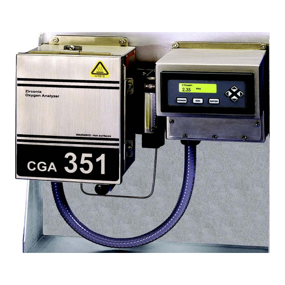
Chapter 1. General Information Chapter 1. General Information Introduction The CGA 351 monitors the oxygen content of any clean and dry gas stream. The analyzer can accurately measure oxygen levels from 0.1 ppm to 100% O , and can even measure oxygen content in reducing gases. This is accomplished with a precision, temperature-controlled, zirconium oxide (zirconia) oxygen sensor. -
Page 12: The Sensor Enclosure
Chapter 1. General Information The Sensor Enclosure The sensor enclosure, which is shown in Figure 2 below, houses the sample measurement components. The functions of these components are as follows: • a zirconium oxide (zirconia) oxygen sensor converts the oxygen concentration of the sample gas into a mV output signal. -
Page 13: The Sample System
Chapter 1. General Information The Sample System In addition to the components supplied with the CGA 351, an external sample system may be required to ensure that the analyzer is fed a properly conditioned sample or calibration gas stream. In particular, the gas must be clean and dry, and it must be delivered to the analyzer at atmospheric pressure. -
Page 14: Principles Of Operation
Chapter 1. General Information Principles of Operation A gas sample is drawn into the inlet port of the analyzer by gas diffusion and a forced flow determined by the external sample system. The sample gas then flows through a ceramic inlet tube and into the annular space between the inlet tube and the inside of the zirconium oxide oxygen sensor. -
Page 15: The Zirconium Oxide Oxygen Sensor
Chapter 1. General Information The Zirconium Oxide Oxygen Sensor The inside and outside of the zirconium oxide oxygen sensor are coated with porous platinum, forming two electrodes. The sample gas flows past the inside of the sensor, while atmospheric air circulates freely on the outside of the sensor. -
Page 16: The Heater Control Circuit
Chapter 1. General Information The Heater Control Circuit The oxygen sensor temperature in the CGA 351 is maintained by a heater, which is part of a complex temperature control loop. This circuit constantly monitors the temperature input from an RTD, compares it to the set point temperature, and turns the heater ON or OFF accordingly. -
Page 17: Chapter 2. Installation
Chapter 2. Installation Chapter 2. Installation Introduction This chapter provides a general description of the standard CGA 351 and gives directions on how to install and wire the analyzer for proper operation. Note: For information regarding component locations and/or wiring connections in an optional enclosure, see Appendix C. -
Page 18: Mounting The Cga 351
Chapter 2. Installation Mounting the CGA 351 This section explains how to mount the analyzer components at the installation site and how to connect the sample system to the analyzer. Note: If more than one analyzer system is being installed, be aware that each system is a matched set (i.e., each sensor enclosure must be matched to a specific electronics enclosure). -
Page 19: Wiring The Analyzer
Chapter 2. Installation Wiring the Analyzer The system components which are housed in the sensor enclosure have already been wired at the factory. These include: • oxygen sensor (TB2) • thermocouple (TB2) • sensor furnace (TB2) To completely wire the CGA 351 zirconium oxide oxygen analyzer, the following items must be connected: •... -
Page 20: Wiring The Inputs (Tb2)
Chapter 2. Installation Connect the input wire to the alarm-1 device to pin Connect the output wire from the alarm-1 device to pin C. If desired, repeat sub-steps a and b to connect alarm-2. Connect any shields to pin G. Proceed to the next section to continue wiring the CGA 351. -
Page 21: Wiring The Line Power (Tb3)
Chapter 2. Installation 2.5.3 Wiring the Line Power (TB3) Terminal block TB3 contains connections for the line power to the CGA 351. To wire the line power, complete the following steps: WARNING! Before proceeding with the section, verify that the line power has been turned off at the external disconnect device. - Page 22 Chapter 2. Installation [no content intended for this page] CGA 351 User’s Manual...
- Page 23 Chapter 2. Installation 17 (432) 8 1/4 (208) 15 1/4 (387) 7/8 (22) 3 7/8 (98) 7/8 (22) 7 3/8 (187) 6 3/4 (171) 14 1/4 (362) 11 1/2 9 1/2 (406) (292) (241) 3 1/2 (89) 6 3/8 (162) Ø1/2 (Ø12.7) 4pl Mounting Mounting Hole...
- Page 24 Chapter 2. Installation TB2 - INPUTS Group Pin # Description Wire # (Color) Sensor (+) 1 (White) Sensor (-) 2 (White) TB3 - POWER* Any Gnd/Shield N.A. Description Pin # Color Thermocouple (+) N.A.(Yellow) Line Black Thermocouple (-) N.A. (Red) Neutral White Any Gnd/Shield...
-
Page 25: Chapter 3. Operation
Chapter 3. Operation Chapter 3. Operation Introduction The CGA 351 is an easily-operated monitoring device. Before applying power, make sure the system has been installed in accordance with the instructions given in Chapter 2, Installation. Note: For information regarding component locations and/or wiring connections in an optional enclosure, see Appendix C. -
Page 26: Powering Up The System
Chapter 3. Operation Powering Up the System Before applying power, check the wiring connections and close both enclosures. Energize the external disconnect device to power up the CGA 351. (See page 25 for powering down instructions). For reliable readings, allow approximately two hours for the analyzer to reach temperature equilibrium before taking measurements. -
Page 27: Initial Screen Displays
Chapter 3. Operation A typical display will be configured to the customer’s needs at the factory. If changes are required, follow the instructions in this section to complete the initial configuration of the digital display. As an aid in performing this task, refer to the menu map in Figure 3-1 on page 28. -
Page 28: Configuration Options
Chapter 3. Operation 3.5.2 Configuration Options Upon entering the User Program, the [Cfg] option is already selected. Simply press [ENTER]. (Notice that the [Disp] option is grayed out at this time. POWER ENTER To proceed with the [1: Cfg] option, press [ENTER]. To abort the operation, press [ESC]. -
Page 29: Using The Auto Range Feature
Chapter 3. Operation Note: The [0:Analog Output], [2:Alarm-1], [2:Alarm-2] [2:Alarm-3] and [2:Alarm-4] options are also available in the above box. To select the desired output(s) from the previous list box, complete the following steps: Use the [] and [] keys to highlight a specific output. For this example, make sure that [0: Display] is selected as one of the outputs. -
Page 30: Configuring The Alarms
Chapter 3. Operation 3.5.4 Configuring the Alarms The first step in setting up the alarms is to assign the correct unit types. To accomplish this, proceed as follows from the Main Menu: Disp Upon entering the User Program, the [Cfg] option is already selected. Simply press [ENTER]. - Page 31 Chapter 3. Operation Detailed instructions for setting up the alarms are provided in Chapter 4, Setup and Calibration. Simply follow those instructions to program the alarm settings listed in Table 2 below. Table 1: Required Alarm Settings Alarm # Trip Type Trip Value Deadband Above...
- Page 32 Chapter 3. Operation 1 Oxygen After pressing [ENTER] at the previous prompt, press [ESC] and the alternate display appears. 3.27 pcnt POWER ENTER When configuring the digital display options, the following two factors must be considered: • Only the digital display and the fault alarm options can be simultaneously assigned to more than one parameter.
-
Page 33: Converting Mv To Oxygen Concentration
Chapter 3. Operation Converting mV to Oxygen Concentration Although the digital display can show the oxygen concentration in ppm or pcnt and the oxygen sensor output in mV, only one parameter can be displayed at any given time. Therefore, it may sometimes be helpful to manually convert a reading from one form to another. - Page 34 Chapter 3. Operation [no content intended for this page] CGA 351 User’s Manual...
- Page 35 Chapter 3. Operation ESC* [*submenu security levels customized for each unit - see table below] Non Fail-Safe pcnt 0: Display Fault Alarm Fail-Safe 0: Fault Alarm Oxygen ARng 0-20mA AR-A 1:Cfg 2: Alarm-1 4-20mA AR-B AOut Type 2: Alarm-2 0-2V deg C Temperature 2: Alarm-3...
- Page 36 [no content intended for this page]...
-
Page 37: Chapter 4. Setup And Calibration
Chapter 4. Setup and Calibration Chapter 4. Setup and Calibration Introduction Although the CGA 351 is set up at the factory with default operational parameter values that are suitable for many applications, the User Program provides a means for customizing many of the setup parameters. Proper setup of the analyzer is very important to ensure accurate data readings. -
Page 38: Setting Up The Alarm Relays
Chapter 4. Setup and Calibration 4.3.1 Setting Up the Alarm Relays To set up the CGA 351’s external alarm relays, corresponding to the wiring terminals on TB1, proceed as follows: Use the [] and [] keys to select [2: Cal] and press [ENTER]. Disp 1: Cal 2: Cal... -
Page 39: Setting The Trip Type
Chapter 4. Setup and Calibration Go to the appropriate sub-section to set the desired alarm feature. Note: The setup of Alarm-1 is used as an example in this manual. To set up Alarm-2, -3 or -4, return to the previous prompt and select the desired option. -
Page 40: Setting The Deadband Value
Chapter 4. Setup and Calibration Alarms..Trip Value Using the [] and [] keys, position the cursor under the desired character. Then, use the [] and [] keys to increment the value. When done, press [ENTER]. 000.00 POWER ENTER The meter now automatically returns to the “Alarm-Features” prompt. Either press [ESC] until you exit the User Program or proceed to the appropriate section to continue setting up the alarms. -
Page 41: Testing The Alarm Relays
Chapter 4. Setup and Calibration 4.3.5 Testing the Alarm Relays Enter the alarm setup menu, as described on page 30. To verify that the alarm relay is functioning properly, the alarm may be operated manually as follows: Alarms..Alarm-Feat Use the [] and [] keys to select [Test], and press [ENTER]. Trip Value Deadband Value Test... -
Page 42: Selecting The Operating Mode
Chapter 4. Setup and Calibration 4.3.6 Selecting the Operating Mode Enter the alarm setup menu, as described on page 30, and proceed as follows: Use the [] and [] keys to select [Fail-Safe], and press [ENTER]. Alarms..Alarm-Feat Deadband Value Test Fail-Safe POWER ENTER... -
Page 43: Setting The Temperature Controls
Chapter 4. Setup and Calibration Setting the Temperature Controls To configure the temperature control circuits of the CGA 351, complete the following instructions. CAUTION! Improper temperature controls settings can seriously degrade the performance of the instrument. Never change these settings without specific instructions from the factory. Use the [] and [] keys to select [1: Cal] and press [ENTER]. -
Page 44: Entering The Setpoint
Chapter 4. Setup and Calibration 4.4.1 Entering the Setpoint Read the CAUTION! on page 35. Enter the temperature control menu as described there and proceed as follows: Use the [] and [] keys to select [Setpoint] and press [ENTER]. Temp-Cntrl Setpoint Sensor Temp Air Offset... -
Page 45: Entering The Sensor Temperature
Chapter 4. Setup and Calibration 4.4.2 Entering the Sensor Temperature Enter the temperature control menu, as described on page 35, and proceed as follows: Use the [] and [] keys to select [Sensor Temp] and press [ENTER]. Temp-Cntrl Setpoint Sensor Temp Air Offset POWER ENTER... -
Page 46: Setting The Air Offset
Chapter 4. Setup and Calibration 4.4.3 Setting the Air Offset CAUTION! Improper temperature controls settings can seriously degrade the performance of the instrument. Never change these settings without specific instructions from the factory. Enter the temperature control menu, as described on page 35, and proceed as follows: Use the [] and [] keys to select [Air Offset] and press [ENTER]. -
Page 47: Selecting The Gas Type
Chapter 4. Setup and Calibration 4.4.4 Selecting the Gas Type CAUTION! Improper temperature controls settings can seriously degrade the performance of the instrument. Never change these settings without specific instructions from the factory. Enter the temperature control menu, as described on page 35, and proceed as follows: Use the [] and [] keys to select [Select Gas Type] and press [ENTER]. -
Page 48: Selecting The Proportional Band
Chapter 4. Setup and Calibration 4.4.5 Selecting the Proportional Band CAUTION! Improper temperature controls settings can seriously degrade the performance of the instrument. Never change these settings without specific instructions from the factory. Enter the temperature control menu, as described on page 35, and proceed as follows: Note: See page 6 for a discussion of the proportional band. -
Page 49: Setting The Integration Time
Chapter 4. Setup and Calibration 4.4.6 Setting the Integration Time CAUTION! Improper temperature controls settings can seriously degrade the performance of the instrument. Never change these settings without specific instructions from the factory. Enter the temperature control menu, as described on page 35, and proceed as follows: Note: See page 6 for a discussion of the integration time. -
Page 50: Setting The Maximum Duty Cycle
Chapter 4. Setup and Calibration 4.4.7 Setting the Maximum Duty Cycle CAUTION! Improper temperature controls settings can seriously degrade the performance of the instrument. Never change these settings without specific instructions from the factory. Enter the temperature control menu, as described on page 35, and proceed as follows: Note: The value selected for this parameter indicates the percentage of time that the heater receives power. -
Page 51: Restoring The Default Values
Chapter 4. Setup and Calibration 4.4.8 Restoring the Default Values To reset the Setpoint, Proportional Band, Integration Time and Max. Duty Cycle parameters to their default values, enter the temperature control menu, as described on page 35, and proceed as follows: IMPORTANT: Restoring the default values invalidates the existing calibration. -
Page 52: Auto Range Analog Output
Chapter 4. Setup and Calibration Auto Range Analog Output This model CGA 351 Zirconia Oxygen Analyzer has been configured with a new software version (CGA351.STD.003.C) that permits the instrument to automatically select the appropriate 4-20 mA analog output range from among 1-4 predefined ranges. -
Page 53: Programming The Auto Ranges
Chapter 4. Setup and Calibration 4.5.2 Programming the Auto Ranges To change the default values for the Auto Range feature (Table 3 above), follow the instructions in this section to set these parameters: • number of ranges • units • zero and span points Choosing the Number of Ranges To select the number of ranges, proceed as follows from the Main Menu:... - Page 54 Chapter 4. Setup and Calibration Selecting the Units To select the units to be used, proceed as follows: A . . Auto_Range_Units ] keys to select the desired units table and press [ENTER]. Use the [ ] and [ ...
-
Page 55: The [Opt-User] Menu
Chapter 4. Setup and Calibration The [Opt-User] Menu After entering the User Program, access the [Opt-User] submenu to perform the following operations: • setting the fault alarm type • setting up the analog output • adjusting the display contrast • setting the display backlight •... -
Page 56: Setting Up The Analog Output
Chapter 4. Setup and Calibration User Fault-Alarm Use the [] and [] keys to select the desired alarm type and press [ENTER]. Non Fail-Safe Fail-Safe POWER ENTER The meter now automatically returns to the “User” prompt. Either press [ESC] until you exit the User Program or proceed to the appropriate section to continue setting up the user options. -
Page 57: Selecting The Analog Output Type
Chapter 4. Setup and Calibration • Zero Trim: adjust the actual output to equal the low end of the analog output range. • Span Trim: adjust the actual output to equal the high end of the analog output range minus the zero setpoint. Proceed to the appropriate sub-section to program the desired analog output feature. -
Page 58: Setting The Zero Setpoint
Chapter 4. Setup and Calibration 4.8.2 Setting the Zero Setpoint Enter the analog output setup menu, as described on page 48, and proceed as follows: Use the [] and [] keys to select [Zero Setpoint], and press [ENTER] User Aout Aout Type Zero Setpoint Span Setpoint... -
Page 59: Setting The Span Setpoint
Chapter 4. Setup and Calibration 4.8.3 Setting the Span Setpoint Enter the analog output setup menu, as described on page 48, and proceed as follows: Use the [] and [] keys to select [Span Setpoint], and press [ENTER]. User Aout Zero Setpoint Span Setpoint Test... -
Page 60: Testing The Analog Output
Chapter 4. Setup and Calibration 4.8.4 Testing the Analog Output Enter the analog output setup menu, as described on page 48, and proceed as follows: Use the [] and [] keys to select [Test], and press [ENTER]. User Aout Span Setpoint Test Zero Trim POWER... -
Page 61: Setting The Zero Trim
Chapter 4. Setup and Calibration 4.8.5 Setting the Zero Trim Using the procedure under Testing the Analog Output on page 52, set the Test Percent to 0. At the analog output setup menu, proceed as follows: Use the [] and [] keys to select [Zero Trim], and press [ENTER]. User Aout Test Zero Trim... -
Page 62: Setting The Span Trim
Chapter 4. Setup and Calibration 4.8.6 Setting the Span Trim Using the procedure under Testing the Analog Output on page 52, set the Test Percent to 100. At the analog output setup menu, proceed as follows: Use the [] and [] keys to select [Span Trim], and press [ENTER]. User Aout Test Zero Trim... -
Page 63: Adjusting The Display Contrast
Chapter 4. Setup and Calibration Adjusting the Display Contrast To adjust the contrast of the LCD display, enter the User Program, as described on page 29, and proceed as follows: Disp Use the [] and [] keys to select [Opt] and press [ENTER]. POWER ENTER Disp... -
Page 64: 4.10 Setting The Display Backlight
Chapter 4. Setup and Calibration 4.10 Setting the Display Backlight To set the LCD display backlight, enter the User Program, as described on page 29, and proceed as follows: Disp Use the [] and [] keys to select [Opt]. Then, Use the [] and [] keys to select [User] and press [ENTER]. -
Page 65: Setting Up The Serial Port
Chapter 4. Setup and Calibration 4.11 Setting Up the Serial Port To set up the serial port, enter the User Program, as described on page 29, and proceed as follows: Disp Use the [] and [] keys to select [Opt]. Then, Use the [] and [] keys to select [User] and press [ENTER]. -
Page 66: Entering The Number Of Data Bits
Chapter 4. Setup and Calibration 4.11.3 Entering the Number of Data Bits At the following prompt, enter the number of data bits in each data string. Use the [] and [] keys to select the desired data length and press [ENTER]. Node I..Data-Length POWER ENTER... -
Page 67: 4.12 Setup And Security Settings
Chapter 4. Setup and Calibration 4.12 Setup and Security Settings After entering the User Program, access the [Opt] submenu to perform the following operations: • setting up the option card slots • setting the security levels Proceed to the appropriate section for specific instructions on the topic of interest. 4.12.1 Setting Up the Option Card Slots To set up the option card slots, enter the User Program as described on page 29 and proceed as follows:... -
Page 68: 4.12.2 Setting The Security Levels
Chapter 4. Setup and Calibration Using a personal computer, enter the appropriate information. Size: Received Block: Write to Slot 1 POWER ENTER This completes the setting up of the option card slot. To exit the User Program, disconnect and reconnect power to system. -
Page 69: Calibrating The Cga 351
Chapter 4. Setup and Calibration 4.13 Calibrating the CGA 351 To calibrate the CGA 351 analyzer, the following steps must be completed: • introduce the chosen calibration gas • regulate the calibration gas flow rate • adjust the calibration setting as required Proceed with the instructions in this section to calibrate the analyzer. -
Page 70: 4.13.2 Regulating The Calibration Gas Flow Rate
Chapter 4. Setup and Calibration 4.13.2 Regulating the Calibration Gas Flow Rate A temporary connection may be made for calibration purposes. However, if a permanent connection is preferred, it should be as short as possible with an isolation valve right at the calibration gas inlet on the analyzer. See the typical sample system in Figure 3 on page 3 for an acceptable arrangement. -
Page 71: 4.13.3 Adjusting The Calibration Setting
Chapter 4. Setup and Calibration 4.13.3 Adjusting the Calibration Setting After the calibration gas flow to the CGA 351 has been established, as described in the previous sections, the calibration gas setting may be adjusted as necessary. To adjust the heater setting, complete the following steps: Verify that the calibration gas flowing through the analyzer meets the requirements for oxygen content (5 ppm), flow rate (400 ±... - Page 72 Chapter 4. Setup and Calibration Setup Diag Use the [] and [] keys to select [Cal] and press [ENTER]. Slct Cal Menu Item POWER ENTER Setup Diag Use the [] and [] keys to select [Heater] and press [ENTER]. Heater POWER ENTER Use the [] and [] keys to select [PPM] and press [ENTER].
- Page 73 Chapter 4. Setup and Calibration PPM-Percent..Cal-Gas When ready, use the [] and [] keys to select [Next] and press [ENTER]. Start the Calibration Gas Next Back Cancel POWER ENTER PPM-Per..Cal-Heater This message appears until the calibration adjustment has been completed (usually about 15–30 minutes).
-
Page 74: 4.14 Checking The Current Settings
Chapter 4. Setup and Calibration 4.14 Checking the Current Settings To aid in monitoring the operation of the CGA 351, a built-in diagnostics routine is included in the User Program. To access this submenu, proceed as follows: Press [ESC] to access the User Program (see page 29). 1 Oxygen 2.71 POWER... -
Page 75: 4.14.1 Checking The Sensor Impedance
Chapter 4. Setup and Calibration 4.14.1 Checking the Sensor Impedance Enter the [Diag] as described on page 66, and proceed as follows: Diag Use the [] and [] keys to select [Impedance] and press [ENTER]. Setup Impedance View Temp Controls POWER ENTER The oxygen sensor impedance, in ohms, is shown. - Page 76 Chapter 4. Setup and Calibration [no content intended for this page] CGA 351 User’s Manual...
-
Page 77: Chapter 5. Service And Maintenance
Chapter 5. Service and Maintenance Chapter 5. Service and Maintenance Introduction The CGA 351 has been designed to provide years of trouble-free operation. However, because of the technical challenges involved in measuring very low levels of oxygen, some difficulties may occasionally be encountered. The procedures for resolving many of these situations are discussed in this chapter. -
Page 78: Checking The Wiring
Chapter 5. Service and Maintenance 5.2.1 Checking the Wiring Complete the two checks listed below to correct any wiring problems. WARNING! Be careful when tightening the terminal block electrical connections. Full line voltage is present on some terminals. IMPORTANT: These symbols indicate Caution - dangerously hot surfaces and risk of electric shock, respectively: Open the cover on the sensor enclosure and remove the lower front panel from the electronics enclosure. -
Page 79: Checking The Thermocouple
Chapter 5. Service and Maintenance 5.2.2 Checking the Thermocouple To check the thermocouple temperature sensor used in the CGA 351, complete the following steps: WARNING! There are very hot surfaces in the sensor enclosure. Touching any of these surfaces without heat resistant gloves will result in serious burns. Note: For information regarding component locations and/or wiring connections in an optional enclosure, see Appendix C. - Page 80 Chapter 5. Service and Maintenance 1000 1100 1200 TEMPERATURE (°C) Figure 4: TC Voltage vs. Temperature Table 6: TC Voltage vs. Temperature E( mV) E( mV) Temp.(°C) Temp.(°C) (0.7981) 29.5841 19.8462 30.0002 21.9783 30.4153 24.1073 30.8296 24.5322 31.2429 24.9566 31.6553 25.3805 32.0668 25.8039...
-
Page 81: Checking The Oxygen Sensor
Chapter 5. Service and Maintenance 5.2.3 Checking the Oxygen Sensor If the thermocouple voltage was within the normal range, the troubleshooting sequence should continue here. Note: For information regarding component locations and/or wiring connections in an optional enclosure, see Appendix C. Disconnect the oxygen sensor (O2) leads (white ) from terminal block TB2. -
Page 82: Oxygen Measurement Errors
Chapter 5. Service and Maintenance Remove the terminal board fuse (see Figure on page 14) and check it for continuity. If the fuse is blown, replace it with a new fuse of the same size and type listed in Chapter 6, Specifications. If the fuse was good, the main voltage supply is bad. - Page 83 Chapter 5. Service and Maintenance Checking for Plumbing Leaks A plumbing leak permits cross-contamination of the reference air and the sample gas. Use the following steps to remedy the problem: Make sure that the calibration gas port in the sample system has not been left open. This would admit atmospheric air into the sample system and force a 20.93% reading.
-
Page 84: Oxygen Reading Above 100
Chapter 5. Service and Maintenance 5.3.2 Oxygen Reading Above 100% An oxygen display reading greater than 100% is almost always caused by reversed wiring of the oxygen sensor. For example, 4% oxygen at 700 °C would generate an oxygen sensor output of +34.69 mV. However, reversed oxygen sensor wiring would cause this reading to be –34.69 mV. -
Page 85: Calibration Responses
Chapter 5. Service and Maintenance Check for Plumbing Leaks A plumbing leak permits contamination of the reference air by the sample gas. The resulting reduction in the ratio of the oxygen partial pressures reduces the mV output from the oxygen sensor and yields a percent oxygen reading that is higher than expected. -
Page 86: Parts Replacement
Chapter 5. Service and Maintenance Parts Replacement The CGA 351 is designed to enable easy and quick servicing, if necessary. This section describes the replacement of major and minor components of the analyzer. However, before actually replacing any component, carefully read the complete instructions to become familiar with the procedures. - Page 87 Chapter 5. Service and Maintenance Open the sensor enclosure cover. Locate the oxygen sensor and the oxygen sensor clips (see Figure 5 on page 85). Note: For information regarding component locations and/or wiring connections in an optional enclosure, see Appendix C. IMPORTANT: Never touch the coating on the oxygen sensor with bare hands.
- Page 88 Chapter 5. Service and Maintenance To install the new oxygen sensor, complete the following steps: CAUTION! When replacing the oxygen sensor assembly, do not touch the new oxygen sensor with bare hands. Handle the assembly by the mounting plate and/or manifold. Insert the sensor/manifold assembly through the opening in the bottom of the sensor enclosure and into the sensor furnace.
- Page 89 Chapter 5. Service and Maintenance Insert the new thermocouple into the sensor furnace, being careful not to strike it against the heating element or the pipe wall inside the sensor furnace. Secure the thermocouple clamp to the bottom of the sensor furnace with the screw previously removed. Route the thermocouple wires through the conduit and into the electronics enclosure.
-
Page 90: The Electronics Enclosure
Chapter 5. Service and Maintenance Feed each of the previously removed sensor furnace wires through the outside, then the inside, of the ceramic block. Reconnect the two wires to the outer terminals on the ceramic block. Make sure the internal power leads are fed all the way through the ceramic block, in order to make a good connection, and that they exit on the opposite side from which they were inserted. - Page 91 Chapter 5. Service and Maintenance Disconnect the main power to the CGA 351. WARNING! Failure to cut the main power at the external disconnect device before proceeding will result in serious personal injury. Remove the four sets of mounting hardware and remove the electronics enclosure from its mounting surface. Remove the eight screws on the rear of the enclosure and lift the mounting plate off the enclosure.
-
Page 92: Recommended Spare Parts
Chapter 5. Service and Maintenance Disconnect the main power to the CGA 351. WARNING! Failure to cut the main power at the external disconnect device before proceeding will result in serious personal injury. Remove the panel meter, as described in a previous section (see page 80). Remove the defective option card from Slot 2 of the panel meter, and install the new option card in its place. - Page 93 Chapter 5. Service and Maintenance Oxygen Sensor Mounting Holes Fitting Nut Ceramic Block Manifold Sensor Furnace View A-A Sensor Furnace (bottom) Mounting Plate Inlet Fitting Thermocouple Sensor Upper Clip Sensor Lower Clip Mounting Screw Mounting Bracket 6 pl Inlet Fitting Mounting Screw Outlet Fitting Mounting Plate...
- Page 94 Chapter 5. Service and Maintenance [no content intended for this page] CGA 351 User’s Manual...
-
Page 95: Chapter 6. Specifications
Chapter 6. Specifications Chapter 6. Specifications General Specifications Accuracy: ± 1% of span at calibration point Repeatability: ± 1% of reading Reproducibility: ± 0.2% of reading in 24 hours ± 1% of reading in 30 days Response Time: Less than 2 seconds for 90% step change Stability: Less than 3% of reading per year Operating Temperature:... -
Page 96: Operating Specifications
Chapter 6. Specifications Operating Specifications Measuring Range: Standard factory setup is 0 to 10 ppm for 4-20mA output. Field selectable for any portion of the range from 0.1 ppm to 100%. Output Range: 0/4 to 20 mA, 0 to 2 V (digital panel meter output) 0 to 1000 mV (oxygen sensor output) Communications: Standard RS232/RS485 Serial Port, PanaView™... -
Page 97: Ordering Information
Chapter 6. Specifications Ordering Information The information below shows how the CGA 351 Analyzer Part Number is configured from the options specified. CGA351- CATEGORY OPTIONS 1 = 100 VAC 2 = 115 VAC Voltage 3 = 220 VAC 4 = 240 VAC 1 = Standard Design on wall mount plate Package 2 = Rack Mount... - Page 98 Chapter 6. Specifications [no content intended for this page] CGA 351 User’s Manual...
-
Page 99: Appendix A. The Nernst Equation
Appendix A. The Nernst Equation Appendix A. The Nernst Equation Introduction The CGA 351 zirconium oxide oxygen analyzer uses the Nernst Equation to calculate the oxygen content of the sample gas. When a Yttrium-doped zirconium oxide ceramic is heated to a temperature above 650°C, it becomes an electrolytic conductor, as vacancies in the crystal lattice permit oxygen ions to diffuse into the ceramic. -
Page 100: The Cga 351 Nernst Equation
Appendix A. The Nernst Equation The CGA 351 Nernst Equation The Nernst Equation specifically applicable to the CGA 351 analyzer is obtained by substituting the above values into the general equation, converting the natural logarithm to the common logarithm (base 10) and converting the units for E to millivolts. - Page 101 r ’ 100% 0.1% 0.01% 0.001% 0.0001% 0.00001% 1,000,000 ppm 100,000 ppm 10,000 ppm 1000 ppm 100 ppm 10 ppm 1 ppm 0.1 ppm Oxygen Concentration Figure A-1: Oxygen Sensor Output at 700°C...
- Page 102 Appendix A. The Nernst Equation Table 10: ppm to mV Conversion at 700°C 305.122 229.995 215.757 290.591 229.421 215.463 282.090 228.862 215.174 276.059 228.317 214.889 271.381 227.786 214.608 267.559 227.269 214.330 264.327 226.763 214.056 261.528 226.270 213.785 259.058 225.788 213.518 256.849 225.317 213.255...
- Page 103 Appendix B. CE Mark Compliance Appendix B. CE Mark Compliance Overview For CE Mark compliance, the CGA 351 zirconium oxide oxygen analyzer must meet both the EMC and LVD directives. IMPORTANT: CE Mark compliance is required only for units used in EEC countries. EMC Compliance For EMC compliance, the electrical connections must be shielded and grounded as shown in Table 139 below.
- Page 104 Appendix B. CE Mark Compliance [no content intended for this page] CGA 351 User’s Manual...
- Page 105 Appendix C. Optional Enclosures Appendix C. Optional Enclosures Introduction Upon request, the CGA 351 analyzer may be supplied in an enclosure other than the standard NEMA-4X enclosures described in Chapter 1 of this manual, General Information. Although the standard installation and wiring instructions set forth in Chapter 2, Installation, will still apply in general terms, some of the details may vary for different enclosure types.
- Page 106 Appendix C. Optional Enclosures C.2.2 Connecting the Sample System For the best results, the sample system should be mounted as close to the CGA 351 analyzer as possible. See Figure 7 below for the location of the Swagelok fittings on the rear panel, and complete the following steps: Using 1/8”...
- Page 107 Appendix C. Optional Enclosures Connect any shields to pin G. RS232 Transmit (TX) COMM RS232 Receive (RX) RS232 Return (RTN) Any Shield or Ground Analog Output (SIG+) 4-20mA Analog Output (SIG-) Normally Open (Standard Mode) ALARM 1 Common Normally Closed (Failsafe Mode) Normally Open (Standard Mode) ALARM 2 Common...
- Page 108 Appendix C. Optional Enclosures C.4.2 Replacing the Fuses If the main power fuses are defective, see Figure 9 below and install new fuses by completing the following steps: Disconnect the main power to the Rack Mount CGA 351. Insert a screwdriver blade behind the fuse access door (to the right of the power switch) and pry it open. Using needle-nose pliers, pull each of the two fuse holders (with an arrow printed on the end) straight out of the unit.
- Page 109 17.15 (436) 18.44 (468) Dimensions are in inches (millimeters). 19.78 (502) 18.67 (474) 18.25 (464) 0.90 (23) 7.00 5.25 6.75 (178) (133) (171) 19.00 (483) CGA 351 User’s Manual...
- Page 110 TB1 - OUTPUTS TB2 - INPUTS NOTE: For proper operation, the unit must be powered by Group Pin # Description Wire Color Group Pin # Description Wire # (Color) the voltage specified at the 1 (White) RS232 Transmit (TX) Brown Sensor (+) time of purchase.
- Page 111 Output Terminal Block Gas Fittings Zirconia Oxygen Analyzer Main Printed Circuit Board Sensor Enclosure (see Figure 5-2) WARNING: Hot surfaces Digital Panel Meter Sample Meter Bypass Meter CGA 351 User’s Manual...
- Page 112 [no content intended for this page]...
- Page 113 Index Alarms EMC Compliance......... .97 Deadband Value .
- Page 114 Index Oxygen Sensor See Sensor Temperature Ambient ..........7 Controls, Default .
- Page 115 Warranty Warranty Each instrument manufactured by Panametrics is warranted to be free from defects in material and workmanship. Liability under this warranty is limited to restoring the instrument to normal operation or replacing the instrument, at the sole discretion of Panametrics. Fuses and batteries are specifically excluded from any liability. This warranty is effective from the date of delivery to the original purchaser.
- Page 116 Warranty [no content intended for this page] CGA 351 User’s Manual...
- Page 118 Copyright 2023 Baker Hughes company. This material contains one or more registered trademarks of Baker Hughes Company and its subsidiaries in one or more countries. All third-party product and company names are trademarks of their respective holders.
Need help?
Do you have a question about the Panametrics CGA 351 and is the answer not in the manual?
Questions and answers