Table of Contents
Advertisement
Quick Links
Advertisement
Table of Contents

Related Manuals for Baker Hughes Panametrics PanaFlow Z1G


Summary of Contents for Baker Hughes Panametrics PanaFlow Z1G
- Page 1 PanaFlow™ Z1G/Z2G User’s manual 910-321 Rev. A...
- Page 3 PanaFlow™ Z1G/Z2G Panametrics gas ultrasonic volumetric flow meter User’s manual 910-321 Rev. A July 2021...
- Page 4 [no content intended for this page]...
-
Page 5: Table Of Contents
Contents Product registration ................. vii Services . - Page 6 3.5 Entering data in the GLOBL menu ..............17 3.5.1 Entering global system data .
-
Page 7: Product Registration
Product registration Safety issues Thank you for purchasing your PanaFlow™ Z1G/Z2G Process WARNING! Gas FlowMeter from Baker Hughes, a Panametrics Company. It is the responsibility of the user to make sure Please register your product at https://info.bakerhughes. all local, county, state and national codes, com/New-Product-Registration-LP.html... -
Page 8: Auxiliary Equipment
Auxiliary equipment Environmental compliance Local safety standards RoHS The user must make sure that he operates all auxiliary The PanaFlow™ Z1G/Z2G Process Gas FlowMeter fully equipment in accordance with local codes, standards, complies with RoHS regulations (Directive 2011/65/EU). regulations, or laws applicable to safety. Waste Electrical and Electronic Equipment (WEEE) directive Working area Panametrics is an active participant in Europe’s Waste... - Page 9 [no content intended for this page]...
-
Page 10: Chapter 1. General Information
Chapter 1. General information Theory of operation Flow profile The PanaFlow Z1G/Z2G Process Gas Flowmeter system uses One of the main factors affecting an ultrasonic flow ultrasonic transit-time technology. A brief description of measurement is the flow profile. If the flow profile is known, transit-time theory follows. -
Page 11: Meter Components
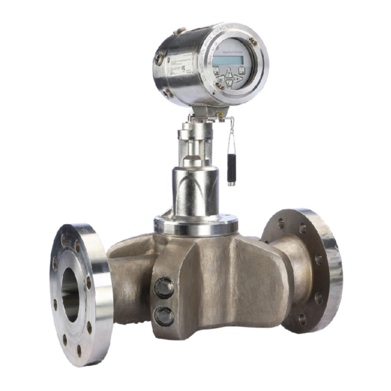
Meter components Figure 1 on page 3 shows a PanaFlow Z1G/Z2G Process Gas Flowmeter system, with the items described in Table 1 below. Table 1: Typical system components Item No. Component Meter Body with Flanges (material list WCB: LCB: CF8: CF8M: CK3MCuN: CD3MWCuN) Transmitter Electronics Magnetic Stylus (for Transmitter Keypad) Mounting Adapter, Transmitter (for local mount only) -
Page 12: Tag Plates
Tag plates 1.7.2 Specification tag plate The Specification Tag Plate (see Figure 3) contains The PanaFlow Z1G/Z2G Process Gas Flowmeter is marked information pertaining to the build and test of the with a variety of labels which provide valuable information spool, such as spool nominal size, flange rating, wall about your specific system. - Page 13 1.7.4 Transmitter tag plate The Flow Transmitter Tag Plate (see Figure 5 on page 5) is affixed to the transmitter and includes the configuration per the model information detailed on the Model Tag Plate. This tag plate also contains the hazardous area certification information for the transmitter.
-
Page 14: Chapter 2. Installation
Chapter 2. Installation Introduction To ensure safe and reliable operation of the PanaFlow Z1G/ Z2G Process Gas Flowmeter, the system must be installed in accordance with the guidelines established by Panametrics engineers. Those guidelines are explained in detail in this chapter. -
Page 15: Flowcell Location Guidelines
• Make sure the difference between the inside diameter of the pipe and that of the PanaFlow Z1G/Z2G Process Gas Flowmeter does not exceed 0.5%, as changes in internal diameters will cause flow profile disturbances. • Make sure any non-symmetrical offset does not exceed 1%, as misalignment between the piping and the meter may cause flow profile disturbances. -
Page 16: Wiring The Line Power
Disconnect any existing power line from its source. Install a cable clamp in the conduit hole closest to the power terminal block. Avoid using the other conduit Loosen the set screw on the rear cover. holes for this purpose to minimize any interference in Place a rod or long screwdriver across the cover in the circuitry from the AC power line. -
Page 17: Wiring The Standard Rs485 Serial Port
Attention! WARNING! To meet CE Mark requirements for all units Always disconnect the line power from the intended for use in the EU or in high electrical PanaFlow Z1G/Z2G Process Gas Flowmeter noise environments, all electrical cables electronics before removing either the front must be installed as described in Appendix or rear cover. -
Page 18: Wiring The Option Cards
If wiring of the unit has been completed, reinstall the rear Table 2: RS485 cable connections cover on the enclosure and tighten the set screw. TB Pin # Signal description IMPORTANT: Prior to use, the option card must be set up and calibrated. RS485+ For more specific instructions on particular option cards, RS485-... -
Page 19: Wiring A Modbus Option Card
2.4.5.2 Wiring an RTD inputs option card 2.4.5.5 Wiring the Foundation Fieldbus interface The PanaFlow Z1G/Z2G Process Gas Flowmeter RTD To connect the Foundation Fieldbus interface, refer to Figure inputs option card provides two or four direct RTD inputs 13 on page 14 and proceed as follows: (designated as A, B, C and D). - Page 23 -08 (AI,HI) -05 (CI,TI,FI) -09 (OI) Pin 1 Pin 1 Pin 1 NOTE: R = RTD Input A = Standard Alarm H = Hermetic Alarm F = Frequency Output T = Totalizer Output I = Current Input C = Current Output O = Blank/No Connection Figure 14: Labels - option card connections...
-
Page 24: Chapter 3. Initial Setup
Chapter 3. Initial setup Introduction 3.3 The magnetic keypad This chapter provides instructions for programming the The glass window on the electronics enclosure includes the data required to place the PanaFlow Z1G/Z2G Process Gas components shown in Figure 15 below. Flowmeter into operation. -
Page 25: Initial Power On Screens
3.4 Initial power on screens parameters and measurements in the designated units. Scroll to the desired Pressure Units selection (absolute or When you power On the PanaFlow Z1G/Z2G Process Gas gauge) and press [ Flowmeter, the display first shows the model name and Do one of the following: software version: •... -
Page 26: Selecting Mass Flow Units
3.5.4 Selecting mass flow units • Skan Only is the preferred technique for locating the acoustic signal and for high velocity measurements. It Scroll to the desired Mass Flow units for the flow rate is more robust in a noisy environment than the Measure ... -
Page 27: Selecting Totalizer Units
Scroll to the desired number of Mass Dec. Digits (digits Table 6: Available volumetric / Totalizer units to the right of the decimal point in the totalized mass flow rate display) and press [ English Metric After completing the above steps, the PanaFlow Z1G/Z2G Process Gas Flowmeter returns to the Channel PROGRAM ACF = Actual Cubic Feet ACM = Actual Cubic Meters... - Page 28 [no content intended for this page]...
- Page 30 [no content intended for this page]...
-
Page 31: Chapter 4. Operation
Chapter 4. Operation Introduction Immediately upon power up, the software version display appears. Then, the meter performs a series of internal checks, which take about 45 seconds, prior to displaying the See Chapter 2, “Installation”, and Chapter 3, “Initial Setup”, flow rate data (see “Initial Power On Screens”... -
Page 32: The Optional Panaview Display
Note: The LCD backlight flashes to signal errors. If the 4.5.1 Programming the LCD display backlight is Off when an error is detected, the display is Note: When you first initialize the PanaFlow Z1G/Z2G Process illuminated briefly, but if the backlight is already On, the Gas Flowmeter, the number of LCD parameters is set to light is interrupted briefly. - Page 33 Table 8: Available measurement parameters Option Bar Description Good Displays the flow velocity. N.A. N.A. VOLUM Displays the volumetric flow. N.A. N.A. +TOTL Displays the forward totalized volume flow. N.A. N.A. -TOTL Displays the reverse totalized volume flow. N.A. N.A. TIMER Displays the total flow measurement time.
-
Page 34: Programming The Panaview Display
Note: The measurement units that appear in these prompts are those selected in the GLOBL-SYSTM menu. Also, when differences in one channel’s programming invalidates an output previously chosen for the other channel, the measurement defaults to the nearest selectable item in the parameter list. -
Page 35: Displaying Multiple Text Windows
4.5.2.1 Displaying multiple process parameters 4.5.3 Pausing measurements The procedure for displaying a single process parameter in On occasion, you may wish to stop taking measurements. a text screen may be repeated to simultaneously display With PanaView, you can direct the PanaFlow Z1G/Z2G multiple process parameters. -
Page 36: Chapter 5. Specifications
Chapter 5. Specifications Operation and performance Repeatability ±0.2% to 0.5% of reading Fluid types Measurement parameters Acoustically conductive gases Mass flow, standard and actual flow, totalized flow, and flow Pipe sizes velocity 2 to 16 in. (50 to 400 mm) Electronics enclosure Meter body materials NEMA Type 4X explosion-proof and weatherproof (IP66) -
Page 37: Dimensions And Weights
5.2 Dimensions and weights Table 9: Example for a 3 in. [80 mm], 2-Path Flowcell Flange Approx. Rating Weight [mm] [mm] [mm] [mm] [mm] [mm] [mm] [mm] [mm] ASME 12.7 19.0 20.0 22.7 44.0 34.7 33.8 66.7 kg 150# RF [322] [481] [190]... - Page 38 [no content intended for this page]...
-
Page 39: Appendix A. Ce Mark Compliance And High Noise Environments
Appendix A. CE Mark compliance and high noise environments A.1 Introduction For CE Mark compliance, the PanaFlow Z1G/Z2G Process Gas Flowmeter must meet the EMC and LVD directives. Attention European Customers! CE Mark compliance is required for all units intended for use in EU countries, and it is also recommended for installation in high electrical noise environments. - Page 40 [no content intended for this page]...
-
Page 41: Appendix B. Gas Process Flowmeter Service Record
Appendix B. Gas process flowmeter service record Option cards installed Whenever an option card is installed or changed in the PanaFlow Z1G/Z2G Process Gas Flowmeter, record the type of card and any additional setup information in the appropriate row of Table 12 below. Table 12: Option cards installed Slot # Type of option card... -
Page 42: Data Entry
B.2 Data entry Record complete and detailed service data for the PanaFlow Z1G/Z2G Process Gas Flowmeter in Table 13 below. Make additional copies of this table as needed. Table 13: Service record Date Description of service Performed by... - Page 43 Table 13: Service record (cont.) Date Description of service Performed by...
-
Page 44: Setup Data
B.3 Setup data After the PanaFlow Z1G/Z2G Process Gas Flowmeter has been installed, setup data must be entered via the User Program prior to operation. Record that information in Table 14 below. Table 14: Setup data General Information Model # Serial # Software Vers. - Page 45 Table 14: Setup data (cont.) Channel - SETUP - Advanced features - Multi K factors K-Factor # Reynolds Number K-Factor K-Factor # Reynolds Number K-Factor Channel - SETUP - Advanced features - Mass flow calculation Mass Flow Mass Flow Density Type Fluid Dens.
- Page 46 Index Symbols +MASS ............25 Electrical connections +TOTL .
- Page 47 LVD statement ..........8 Modbus .
- Page 48 Tup ............25 Tu S .
- Page 49 [no content intended for this page]...
- Page 50 Measurement and control Certification and safety statements for the PanaFlow Z1G/Z2G ultrasonic gas flow meters When installing this apparatus in potentially hazardous • The product cannot be repaired by the user; it must be areas, the following requirements must be met: replaced by an equivalent certified product.
- Page 51 Standards EN 60079-0:2012 + IEC 60079-0:2011 A11:2013 IEC 60079-1:2014 EN 60079-1:2014 IEC 60529:2001 EN 60529:1991 + A1:2000 ATEX Specific conditions of use: The flameproof joints of the equipment are not intended US/CANADA: to be repaired. Consult the manufacturer if dimensional Specific conditions of use: information on the flameproof joints is necessary.
- Page 52 Markings Following marking shall additionally appear on the flowcell: Shall appear on the meter as shown below for the AC and DC powered versions. PANAMETRICS LLC PANAMETRICS LLC panametrics.com PANAMETRICS LLC Shall appear on the meter as shown below. PANAMETRICS LLC PANAMETRICS LLC...
- Page 53 Connection and wiring diagram (ref. dwg. 702-1846) RS232/RS485/4-20 ANALOG OUTPUT TERMINAL BLOCK DESCRIPTION OPTION CONTACT TERMINAL BLOCK 1 TX (RS485 +) TRANSMIT 2 RX (RS485 -) RECEIVE 3 COM (SHLD) COMMON OPTIONAL 4 CTS CLEAR TO SEND MODBUS CONNECTION 5 DTR DATA TERMINAL READY 6 AOUT B- 4-20 OUTPUT 2 RTN...
- Page 54 EU DECLARATION OF CONFORMITY Panametrics LLC PanaFlow™ Z1G Flowmeter PanaFlow™ Z2G Flowmeter1 Panametrics LLC, 1100 Technology Park Drive Billerica, MA 01821, USA declare under our sole responsibility that the PanaFlow ZxG measurement system , consisting of a meter electronics and associated transducers and a pressure retaining flow cell, is in conformity with the following harmonising directives: •...
- Page 55 Digital Solutions- Panametrics 1100 Technology Park Drive Billerica, MA 01821 USA ROHS_XXXX ZxG RoHS Certificate of Compliance EU Directive 2011/65/EU for the Restriction of Hazardous substances in the manufacture of specific electrical and electronic equipment. Although this restriction does not apply to components, per 2011L0065, Article 2 (Scope), item 4(c), we recognize that some customers may require compliant components to satisfy their compliance requirements.
- Page 56 ЕС ДЕКЛАРАЦИЯ ЗА СЪОТВЕТСТВИЕ EU PROHLÁŠENÍ O SHODĚ (č. XXXX) EU-KONFORMITÄTSERKLÄRUNG (Nr. (№ ХХХХ) OVERENSSTEMMELSESERKLÆRING XXXX) (nr. XXXX) Model výrobku/výrobek (číslo Produktmodell/Produkt výrobku, typu či dávky nebo sériové (Produkt-, Typen-, Chargen- oder Модел на продукта/продукт (номер Produktmodel/produkt (produkt-, číslo): Seriennummer): на...
- Page 57 DÉCLARATION UE DE CONFORMITÉ EU IZJAVA O SUKLADNOSTI (br. XXXX) EU-MEGFELELŐSÉGI NYILATKOZAT VAATIMUSTENMUKAISUUSVAKUUTUS (n o XXXX) (XXXX. sz.) Uzorak proizvoda/proizvod (broj proizvoda, šarže, vrste ili serijski broj): (nro XXXX) Modèle de produit/produit (numéro Termékmodell/termék (termék-, de produit, de type, de lot, ou de típus-, tétel- vagy sorozatszám): (2a) Naziv i adresa proizvođača Tuot...
- Page 58 EU-CONFORMITEITSVERKLARING (Nr. DEKLARACJA ZGODNOŚCI UE (nr DECLARAÇÃO UE DE CONFORMIDADE DECLARAȚIE UE DE CONFORMITATE XXXX) XXXX) (n. o XXXX) (NR. XXXX) Productmodel/product (product-, Model produktu/produkt (numer Modelo do produto/produto (número Modelul de produs/produsul type, partij- of serienummer): produktu, typu, partii lub serii): do produto, do tipo, do lote ou da (numărul produsului, tipului, lotului série):...
- Page 59 Oil & Gas; Energy; Healthcare; Water and Wastewater; Chemical Processing; Food & Beverage and many others. Join the conversation and follow us on LinkedIn linkedin.com/company/panametricscompany Copyright 2021 Baker Hughes Company. All rights reserved. 910-321 Rev. A panametrics.com BHCS39066 (08/2021)
Need help?
Do you have a question about the Panametrics PanaFlow Z1G and is the answer not in the manual?
Questions and answers