
Related Manuals for Solar-Log 350


Summary of Contents for Solar-Log 350
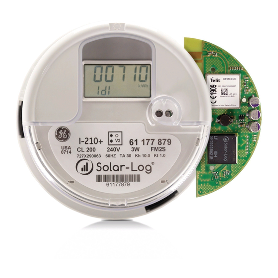
- Page 1 Installation Manual Installation Manual Solar-Log® Socket Meter Solar-Log® Socket Meter...
-
Page 2: Table Of Contents
Table of Contents Getting Started Required hardware Before you begin Installation Guide Safety Precautions Meter Installation Solar-Log 350 (and Solar-Log 350 LAN) Wiring Diagram Step by Step Solar-Log 360 Wiring Diagram Step by Step Solar-Log 370 Wiring Diagram Optional Connections to External Devices... - Page 3 Solar-Log® WEB Registration (Before or After Installation) Warranty Technical Support For additional support please visit www.solar-log-america.com under the Service & Support tab, and our experts will provide answers to any questions concerning Solar-Log ® products or call our technical support team at (203) 702-7189. Online Support www.t-mobile.com/coverage.html...
-
Page 4: Getting Started
Onsite with cellphone – must have 2 bars of signal showing GPRS/E/3G/4G or LTE • T-Mobile: offsite at www.t-mobile.com/coverage.html • AT&T: offsite at www.att.com/maps/wireless-coverage If cellular coverage is not available, please use Solar-Log 350 LAN (Part No. 823210) or Solar-Log 370 (Part No. 225852) and connect to an internet router via Ethernet. -
Page 5: Installation Guide
Installation Guide Safety Precautions DANGER! Lethal voltage inside the meter! Thoroughly read and understand this guide before installing and operating the unit. Follow all instructions and safety precautions in this guide. Prior to performing any work turn off all power supplying the equipment in which the meter is to be installed. -
Page 6: Meter Installation
The socket jaws provide heavy contact force with the help of spring. Refer to page 7 for installing a Solar-Log 350 (or Solar-Log 350 LAN) Refer to page 10 for installing a Solar-Log 360 Refer to page 13 for installing a Solar-Log 370... -
Page 7: Solar-Log 350 (And Solar-Log 350 Lan)
Solar-Log 350 (and Solar-Log 350 LAN) The Solar-Log 350 is a universal monitoring device for PV production and reporting. This easy to install device is compatible with all residential solar PV inverters and does not require on-site confi guration. -
Page 8: Wiring Diagram
The wiring diagram includes rudimentary connection diagrams and is not intended as an installation guide. The diagrams are shown for informational purposes only. *Internet Router is not provided **Solar-Log 350 LAN is only recommended when cellular service is weak or unavailable onsite. -
Page 9: Step By Step
& power. and national electric code See pg 20. Step 3 Step 6 Plug Solar-Log 350 & GE Check LEDs (located at Meter into socket and re- bottom) place cover Flashing Green (for Solar-Log 350) -
Page 10: Solar-Log 360
This easy to install device is compatible with all residential solar PV inverters and does not require on-site confi guration. Included with the Solar-Log 360 is a Solar-Log 10 (bi-directional meter) and 2 current transducers (CTs) for measuring home consumption. -
Page 11: Wiring Diagram
Wiring Diagram Notice: The wiring diagram includes rudimentary connection diagrams and is not intended as an installation guide. The diagrams are shown for informational purposes only. -
Page 12: Step By Step
- check arrows for correct Flashing Yellow energy fl ow! 2. do voltage Searching for SL10 device tapping, 3. wire RS485) Solid Green Finished Step 4 Other LEDs See Troubleshooting Plug Solar-Log 360 & GE Meter into socket and re- place cover... -
Page 13: Solar-Log 370
Solar-Log 370 The Solar-Log 370 is a universal monitoring device for PV production and reporting with The Solar-Log 370 is a universal monitoring device for PV production and reporting with numerous connectivity options. This device is compatible with all residential solar PV inverters with easy on-site installation. -
Page 14: Wiring Diagram
Wiring Diagram (not for inverter direct monitoring) Notice: The wiring diagram includes rudimentary connection diagrams and is not intended as an installation guide. The diagrams are shown for informational purposes only. -
Page 15: Optional Connections To External Devices
Optional Connections to External Devices including Inverter Direct *120V outlet and power supply required for weather sensor. Power supply sold separately (part number 869203). **Some inverter brands require direct monitoring via LAN connection. Consult the Solar-Log 370 Inverter Installation Appendix at www.solar-log-america.com/devices. -
Page 16: Step By Step
Step by Step Step 1 Step 4 Switch main breaker OFF Plug Solar-Log 370 & GE in distribution panel and Meter into socket and re- ensure all other voltage place cover sources are off. Step 2 Step 5 Install socket & electrical... - Page 17 Step 7 Solid Green Check LEDs (located at Using Cellular Connection bottom) Green with Quick Blink Once Every 5 Seconds Flashing Green Using LAN Connection Waiting for internet connection Other LEDs Flashing Yellow See Troubleshooting Searching for external devices...
-
Page 18: Device Detection
Step 2 Click on ‘add new device’ and add all external devices like inverter, consumption meter (Solar-Log 10), or weather station accordingly. Press SAVE. Step 3 Once all external devices have been entered click on ‘start device detection’. It takes until the next data communication interval for the results to be visible. -
Page 19: Confirm Cellular Connection When Using Lan Communication
Confirm Cellular Connection When Using LAN Communication If the meter is connected to an internet router it will connect via Ethernet and the green LED will flash once every 5 seconds. To confirm that cellular service is also working as a backup for data transfer: •... - Page 20 If the meter displays “Ser” error in the lower-left display section, it implies that the meter has been connected in a 12S/25S socket or to 3 phase service. Please confirm that the meter is connected correctly in a 2S socket. For all other issues or error messages please contact Solar-Log ® Support at (203) 702-7189...
- Page 21 Signal too low Connect LAN to internet router or check cable Flash SIM card problem Call support (below) Flash SIM card roaming problem Call support External device offl ine Check external device For further assistance call Solar-Log Support (203) 702-7189 ®...
- Page 22 Solar-Log® WEB Registration Before or After Installation Step 1: Prepare Please complete the following plant information to have on-hand for Solar-Log® WEB Registration *Plant Name (as it will appear in the Solar-Log WEB portal): ® *Address: Plant size in kWp (total power of the PV plant):...
- Page 23 2. Complete the form with the information from Step 1 and select “Register Now”. 3. You will receive a confirmation email within 5 minutes. Click the link provided to con- firm your email address. 4. Please allow 48 hours for Solar-Log to complete the setup of your portal. Once regis- ®...
- Page 24 SDSI or used in conjunction with SDSI products. The warranty conditions of those manufac- turers apply to their products. The SDSI Products covered by this Warranty are the Solar-Log 350, 350LAN, 360, 370, Solar-Log 10 (collectively, the “Product”).
- Page 25 2. Warranty Period This Warranty shall be in effect for a period of One (1) Year starting from the purchase of the Product by the Customer (“Warranty Period”), regardless of whether the Customer purchased the Product from a wholesaler, distributor or installer. 3.
- Page 26 the Installation Manual. If the Customer is not the installer of the Product, it shall be in any case fully responsible for the proper installation (in respect of the instructions and recommendations of the Installation Manual) by a qualified installer. SDSI excludes all responsibility for defects caused by wrongful installation or for any errors in installation whether installed by the Customer itself or any third party installer.
- Page 27 Warranty. 12) If the Product stops reporting data to the Solar-Log WEB portal and remains disconnected for more than 6 months.
- Page 28 13) If the Product’s original identification markings (including serial number, certification or trade- mark) have been altered, scratched, or removed. 14) If the Product is installed in violation of local, state or federal codes and standards. 15) Normal wear and tear do not constitute a cause for repair work under this Warranty (e.g. super- ficial or cosmetic defects, scratches, marks or dents, which do not influence the functionality or the Product).
- Page 29 common carrier. In the event the Customer fails to supply this information, this Warranty shall be void and of no effect. The Customer shall bear the costs of SDSI’s remedial warranty efforts (including removal and re- placement of systems, structures or other parts of Customer’s facility), de-installation, decontam- ination, reinstallation and transportation of defective Products to SDSI and back to Customer.
- Page 30 In addition, SDSI U.S. Return Policy or International Return Policy will apply which is available at www.solar-log-america.com SDSI becomes the owner of the defective parts of the Product or the defective Product.
- Page 31 SDS Group Privacy Policy which is available at www. solar-log-america.com. 10. No warranty claim Returning the Product to SDSI during the Warranty Period does not automatically mean that it will be repaired free of charge. Upon receiving the Product, SDSI reserve the right to check the validity of the Customer Warranty and the request for Warranty service.
- Page 32 Sticker with Solar-Log ® Serial Number EasyCode Solar Data Systems, Inc. • Bethel, CT 06801 • www.solar-log-america.com Subject to change without notice - USA | © 2018 | Version 2.6 | Part# 863325...
Need help?
Do you have a question about the 350 and is the answer not in the manual?
Questions and answers