Table of Contents
Advertisement
Quick Links
IGBT Power module evaluation kit - Semitop2 power board
Introduction
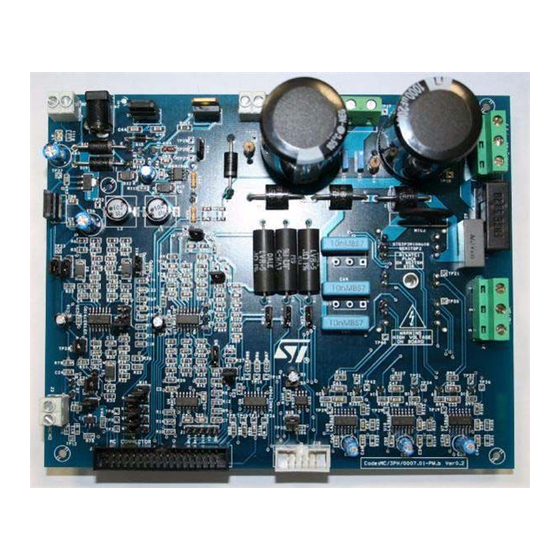
The Semitop2 evaluation board STEVAL-IHM011V1 is a complete platform to evaluate
STMicroelectronics power module devices (Semitop 2). Based on a cost effective, flexible
and open design, it is an evaluation platform compatible with the latest STMicroelectronics
microcontroller based solution. It includes the STG3P2M10N60B IGBT Power Module up to
10 amps, 600 voltage (see
connector (MC-Connector) and hardware features for developing motor control applications
including hardware protection features such as current and thermal protection.
Figure 1.
Features
■
34-pin dedicated motor control connector
■
5-pin Hall sensor/encoder input
■
Tachometer sensor input
■
Support for 5 V or 3.3 V microcontroller
■
Three configurations for current detection:
– 1 shunt resistor
– 3 shunt resistors or
– 3 external ICS (Insulated Current Sensor)
■
Current amplification network
■
BEMF detecting network
■
Hardware current protection
■
Hardware thermal protection (using on board temperature sensor)
■
Resistive brake network
Note:
1
The kit has been designed and tested to work with European mains so maximum 380 VDC.
July 2007
Note:
1). The STEVAL-IHM011V1 features a motor control
STEVAL-IHM011V1
Rev 2
UM0428
User manual
www.st.com
1/27
Advertisement
Table of Contents

Related Manuals for ST STEVAL-IHM011V1


Summary of Contents for ST STEVAL-IHM011V1
- Page 1 IGBT Power module evaluation kit - Semitop2 power board Introduction The Semitop2 evaluation board STEVAL-IHM011V1 is a complete platform to evaluate STMicroelectronics power module devices (Semitop 2). Based on a cost effective, flexible and open design, it is an evaluation platform compatible with the latest STMicroelectronics microcontroller based solution.
-
Page 2: Table Of Contents
Contents UM0428 Contents System architecture ......... 4 Safety and operating instructions . - Page 3 UM0428 Contents References ..........26 Revision history .
-
Page 4: System Architecture
High side/low side pairs of one signal for each leg. In the system proposed three legs are present (three-phase inverter). The Power Board STEVAL-IHM011V1 is based on a power module (STG3P2M10N60B) that converts the control signal in the power signals to drive the motor. The connection between the control board and the power board is performed through a dedicated 32-pin connector called “motor control connector”... -
Page 5: Safety And Operating Instructions
UM0428 Safety and operating instructions Safety and operating instructions General During assembly and operation, the IGBT power module eval kit poses several inherent hazards, including bare wires, moving or rotating parts, and hot surfaces. There is danger of serious personal injury and damage to property, if it is improperly used or installed incorrectly. -
Page 6: Stg3P2M10N60B Power Module Characteristics
STG3P2M10N60B power module characteristics UM0428 Warning: Do not touch the design boards after disconnection from the voltage supply, as several parts and power terminals which contain possibly energized capacitors need to be allowed to discharge. STG3P2M10N60B power module characteristics The STG3P2M10N60B is a 1-phase bridge rectifier plus a 3-phase inverter IGBT all ®... -
Page 7: Power Board Electrical Characteristics
Before performing the test, the power board must be set up as described in Section 7.3: Power board setup. Table 2. Control board electrical characteristics STEVAL-IHM011V1 Power board electrical characteristics Unit without voltage doubler (220 Vac configuration) AC Input Voltage J6 with voltage doubler (110 Vac configuration) DC Input Voltage –... -
Page 8: Board Architecture
Board architecture UM0428 Board architecture The STEVAL-IHM011V1 can be schematized as in Figure Figure 4. Power board architecture The power board is developed around the IGBT power module that contains the inverter bridge constituted of six IGBT power switches and the AC rectifier bridge (see Figure The board has been designed to operate with a 5 V or 3.3 V microcontroller so the power... -
Page 9: Mc Connector
UM0428 Board architecture In the three-shunt configuration, the amplification is positive and an offset is added to keep the negative values of the current in the range of ADC also. The levels of the amplified signals are compatible with 3.3 V microcontrollers. To use the ICS, the operational amplifiers U1 network must be modified according to sensor characteristics. - Page 10 Board architecture UM0428 systems. For instance it is possible for any user to redesign the control board keeping the compatibility with the power board if the standard MC connector configuration is used. Figure 6. MC Connector pin out Fault (Shut_Down L6386) PWM_1H Dedicated PWM_1L...
-
Page 11: Mains Connector
UM0428 Board architecture Table 4. Motor control connector (continued) Pin N. Description Pin on ST7MC Ground Phase B current MCCFI Ground Phase C current Ground NTC PYPASS RELAY Ground Dissipative BRAKE Ground HEATSINK temperature AIN0 PFC SYNC ICAPx_B PFC PWM OCMP1_B Ground ENCODER A... -
Page 12: Ics Connector
Board architecture UM0428 ICS connector The ICS Connector is used to connect the Insulated current sensor to the board. See Table 5 for pin out. Figure 8. ICS connector Table 5. ICS connector pin out Function Ground Ground ICS Input C GND ICS Input C ICS Input B GND ICS Input B... -
Page 13: Board Schematics
UM0428 Board schematics Board schematics Figure 9. Power board schematic - page 1 13/27... - Page 14 Board schematics UM0428 Figure 10. Power board schematic - page 2 14/27...
-
Page 15: Hardware Protection Features
UM0428 Motor control demonstration Hardware protection features The L6386 drivers are used to drive the three-phase bridge. The drivers are provided with internal protection features used for hardware current and thermal protection. Hardware current protection has been set up for a current level of 4 amps. If a current greater than this value flows inside the motor, the inverter is shut down and an emergency fault signal is sent to the micro by the MC connector. -
Page 16: Hardware Requirements
Power board setup 7.3.1 Configuring AC input range and shunt resistors configuration The STEVAL-IHM011V1 power board can be configured for two ranges of AC input voltage: European standard mains voltage (220 Vac) or American standard mains voltage (110 Vac). 16/27... -
Page 17: Jumpers Settings
UM0428 Motor control demonstration The first configuration is a simple rectifier, but the second configuration is a voltage doubler. Using the first configuration with an AC input of 220 V, the bus voltage obtained is 310 DC volt. Using the second configuration with an AC input of 110 V, the bus voltage obtained is the same 310 DC V. - Page 18 Motor control demonstration UM0428 Table 6. Jumpers settings Name Selection Description If sensorless control is set (see W2), it connects motor phase A to MC connector through Between 1-2 R2-R3-R5-R6 feedback resistors. In this case the microcontroller internal comparator is used to detect the BEMF.
- Page 19 UM0428 Motor control demonstration Table 6. Jumpers settings (continued) Name Selection Description If sensorless control is set (see W9), it connects motor phase C to MC connector through Between 1-2 R59-R60-R61-R62 feedback resistors. In this case the microcontroller internal comparator is used to detect the BEMF.
-
Page 20: Microcontroller Voltage Setting
Motor control demonstration UM0428 Table 7. Configuration for each firmware Driving strategy Jumper name Selection W2, W4, W9 open AC Ind. Motor closed W1, W7, W11 open W2, W4, W9 between (1-2) BLDC Sensorless open W1, W7, W11 between (1-2) W2, W4, W9 between (2-3) BLDC Sensored... -
Page 21: Sensor Voltage Setting
UM0428 Motor control demonstration Sensor voltage setting W6 sets the voltage reference supplied to the Hall sensor or to the Encoder. If W6 is set between 2-3, +5 V is supplied to the sensor. If W6 is set between 1-2, the same voltage of the microcontroller is supplied to the sensor (+5 or +3.3 depending W13). -
Page 22: Changing The Current Hardware Protection Level
Motor control demonstration UM0428 7.5.2 Changing the current hardware protection level The hardware protection level has been set by design to 4 amps but it is possible to change this value soldering one (or three) resistor(s) of specific value as described in Figure Figure 13. - Page 23 UM0428 Motor control demonstration Table 9. Bill of materials Item Reference Part name/value power C1,C10,C14 33 pF 50 V C2,C50 100 nF 10 V C3,C9,C12 10 nF 25 V C4,C11,C15 10 pF 50 V C5,C16,C51 4.7 µF 25 V C6,C13,C18,C21 27 nF 25 V C7,C8,C20,C23,C24,C25,C57...
- Page 24 Motor control demonstration UM0428 Table 9. Bill of materials (continued) Item Reference Part name/value power 2 screw connector MC Connector 34 pin double line 3 screw connector 2 screw connector 3 screw connector 2 screw connector 2 screw connector JACK Power supply 15 V ICC Connector 10 pin double line GREEN LED 1.5 mH .3 A / 1mH .3 A...
- Page 25 UM0428 Motor control demonstration Table 9. Bill of materials (continued) Item Reference Part name/value power R69,R128 3.9 kΩ 1/4 W 22 kΩ 1/4 W 39 kΩ 1/4 W 100 Ω 1/4 W R85,R86,R87,R88,R89,R90,R112,R119 47 kΩ 1/4 W R92,R98 47 kΩ 120 Ω...
- Page 26 References UM0428 References This user manual provides information about using your STEVAL-IHM011V1 and its hardware features. For additional information about supporting software and tools, please refer to: STG3P2M10N60B, L6386, VIPer12 Datasheet. Complete information about devices features and characteristics. ST7MC motor control related application notes. Complete information about motor control libraries developed for ST7MC microcontroller.
- Page 27 No license, express or implied, by estoppel or otherwise, to any intellectual property rights is granted under this document. If any part of this document refers to any third party products or services it shall not be deemed a license grant by ST for the use of such third party products or services, or any intellectual property contained therein or considered as a warranty covering the use in any manner whatsoever of such third party products or services or any intellectual property contained therein.
Need help?
Do you have a question about the STEVAL-IHM011V1 and is the answer not in the manual?
Questions and answers