Table of Contents
Advertisement
Quick Links
UM0971
User manual
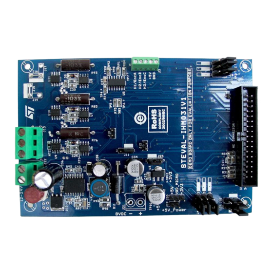
STEVAL-IHM031V1 low voltage
three-phase inverter demonstration board
Introduction
The STEVAL-IHM031V1 demonstration board is a low voltage three-phase power stage
inverter designed to perform permanent magnet motor controls. To this purpose, it must be
connected to an additional control logic stage (usually based on an 8/32-bit microcontroller).
According to the existing wide range of motor types and control techniques, it has been
designed to offer large flexibility by allowing full configurability.
In particular, it can be used for implementing scalar control (also known as current six-step
mode or trapezoidal shaped back-EMF) and field oriented control (sinusoidal-shaped back-
EMF PMSM).
The system has been specifically designed to achieve accurate and fast conditioning of the
current and back-EMF feedbacks, thereby matching the requirements typical of high-end
applications such as field oriented motor control. Back-EMF conditioning networks can
include an amplification stage for managing very low motor speed. Circuit networks are
provided to implement different techniques of sensorless speed and rotor position detection.
The input voltage range is from 12 V up to 24 V with no need to set any jumper for selecting
the input voltage level. Nominal power is up to 120 W. A dedicated power supply has been
designed to provide power +5 V and +3.3 V voltages to supply the control stage board. The
latter can be connected to the STEVAL-IHM031V1 board by using a dedicated motor control
connector, generally available in most boards based on microcontrollers produced by ST.
The three-phase inverter bridge is based on the STS8DNH3LL power MOSFET dual-in-
package SO-8 and L6387E gate driver. The board is self-protected by overcurrent events
and for each power MOSFET the case temperature is sensed through a temperature
sensor. A connector exists to read signals coming from encoder and Hall sensors.
Figure 1.
STEVAL-IHM031V1 demonstration board
October 2010
Doc ID 17701 Rev 1
1/45
www.st.com
Advertisement
Table of Contents

Related Manuals for ST STEVAL-IHM031V1


Summary of Contents for ST STEVAL-IHM031V1
-
Page 1: Figure 1. Steval-Ihm031V1 Demonstration Board
+5 V and +3.3 V voltages to supply the control stage board. The latter can be connected to the STEVAL-IHM031V1 board by using a dedicated motor control connector, generally available in most boards based on microcontrollers produced by ST. -
Page 2: Table Of Contents
Contents STEVAL-IHM031V1 features ........6 Electrical and functional characteristics ......6 Target application . - Page 3 UM0971 Contents Connector placement ........25 Connector description .
- Page 4 List of tables UM0971 List of tables Table 1. Absolute maximum ratings ..........10 Table 2.
- Page 5 STEVAL-IHM031V1 demonstration board ........
-
Page 6: Steval-Ihm031V1 Features
Safety and operating instructions 1.3.1 General Warning: During assembly and operation, the STEVAL-IHM031V1 demonstration board poses several inherent hazards, including bare wires, moving or rotating parts, and hot surfaces. There is a danger of serious personal injury and damage to property, if the kit or its components are improperly used or installed incorrectly. -
Page 7: Demonstration Board Intended Use
1.3.5 Demonstration board operation A system architecture which supplies power to the STEVAL-IHM031V1 demonstration board is equipped with additional control and protective devices in accordance with the applicable safety requirements (e.g., compliance with technical equipment and accident prevention rules). -
Page 8: Board Description
● Control unit Interface: this is a signal interface (motor control connector) where a control unit board can be connected to implement motor driving. ST distributes several demonstrators and demonstration boards which are compatible with this interface. For references, please read Section Figure 2. -
Page 9: Power Supply Circuit
Board description Power supply circuit The STEVAL-IHM031V1 board is designed to work with an input voltage bus ranging from 12 V up to 24 V (nominal values). The bus voltage supplies the three-phase inverter stage. To allow proper working below the nominal 12 V lower voltage limit, an opportune power supply stage has been designed, taking into account several aspects, such as: ●... -
Page 10: Table 1. Absolute Maximum Ratings
Board description UM0971 Figure 4. LD1117 family packages DPAK TO-220 SO-8 SOT-223 Table 1. Absolute maximum ratings Symbol Parameter Value Unit DC input voltage Power dissipation Storage temperature range -40 to +150 °C for C version -40 to +125 °C Operating junction temperature range for standard version 0 to +125... -
Page 11: Table 3. Electrical Characteristics Of The Ld1117#50
UM0971 Board description Table 2. Electrical characteristics of the LD1117#33 (continued) Symbol Parameter Test condition Min. Typ. Max. Unit = 100 mA Dropout voltage = 500 mA 1.05 1.15 = 800 mA 1.10 Thermal regulation = 25 °C, 30 ms pulse 0.01 Table 3. -
Page 12: L4976 Characteristics
2.2.3 Inverse polarity protection To prevent accidental polarity inversion when supplying the STEVAL-IHM031V1 board through connector J22, a protection circuit has been provided. It is made up of a diode and a fuse of 6.3 A. In the case of polarity inversion occurring, the fuse F1 is permanently damaged and needs to be replaced before the next system operation. -
Page 13: Figure 6. Block Diagram
UM0971 Board description is enabled to work with voltage rail up to 600 V. The logic inputs are CMOS/TTL compatible for ease of interfacing with controlling devices. It features: ● High voltage rail up to 600 V ● dV/dt immunity ±50 V/nsec in full temperature range ●... -
Page 14: Three-Phase Inverter Power Switches
Board description UM0971 The driver L6387E offers an interlocking feature to avoid undesired simultaneous turn-on of both driven power switches. Three-phase inverter power switches 2.4.1 STS8DNH3LL characteristics The STS8DNH3LL is a dual N-channel (30 V - 0.018 Ω - 8 A) low gate charge STripFET™ III power MOSFET in the SO-8 package. -
Page 15: Bemf Conditioning Network
There exists various implementations of sensorless BLDC control techniques, most of them using motor back-EMF voltage as rotor position sensing signal. In ST technical papers and application notes (please refer to Section 6) some topologies, their advantages and drawbacks, as well as their practical implementation, are described in detail. -
Page 16: Zero-Crossing Methods For Bemf Reading
Putting the switch on Pos 1, the motor phase voltage is directly input to the voltage divider block. When the patented ST zero-crossing method is used, the voltage divider is simply made up of a 10 kΩ series resistor for limiting the current to the control unit that processes the signal. -
Page 17: Virtual Neutral (Or Natural) Point Reconstruction
When the classic analog method is used for back-EMF reading, there is a need to reconstruct the virtual neutral point of motor windings (when star connected). To this aim, there are different schemes. In particular, STEVAL-IHM031V1 allows implementation of both the following (though not at the same time):... -
Page 18: Current Sensing And Conditioning Network
Board description UM0971 Table 7. Virtual neutral point reconstruction Jumper Position Description Between 1-2 Three resistors used Between 2-3 DC bus voltage divider Current sensing and conditioning network 2.6.1 Bipolar current reading configuration The details of bipolar current sensing (also referred to as Alternating AC) reading configuration is shown in Figure 11. -
Page 19: Unipolar Current Reading Configuration
UM0971 Board description Equation 7 ⋅ ------------------------------------------------------ - ----------- - ⎛ ⎞ R2 ⋅ ------- - ------- - ------- - ⎝ ⎠ With the resistor values actually used in the circuit schematic, it is: R1=5100 Ω ● R2=920 Ω ● R3=470 Ω... -
Page 20: Figure 12. Single-Shunt Configuration
Board description UM0971 Figure 12. Single-shunt configuration It is possible to calculate the voltage on the output of the op amp Vout as the sum of a bias voltage, Vbias, and an amplification of voltage drop across the shunt resistor (G): Equation 8 ⋅... -
Page 21: Three-Shunt Current Reading Configuration
UM0971 Board description Table 9. DC current jumper configuration Jumper Position Not present Between 2-3 Not present This means that the maximum instantaneous current amplifiable without distortion is 7.7A (corresponding to Vout = 5 V). The user can modify the maximum current value by changing the shunt resistor values. -
Page 22: Overcurrent Protection
Board description UM0971 2.6.5 Overcurrent protection A hardware overcurrent protection has been implemented through a comparator. The typical transition speed under the 5 V supply is about 2 µs from 50 mV overdrive. Figure 13. Overcurrent protection circuit With the resistor values actually used in the circuit schematic: R1= 15 kΩ, R2=3 kΩ... -
Page 23: Temperature Sensing And Protection
Board description Temperature sensing and protection A hardware temperature sensing has also been implemented on the STEVAL-IHM031V1 demonstration board. As this signal is available on the MC connector, with a proper control logic, this feature helps to fully protect the switches against damage when power loss reaches some defined value. -
Page 24: Descriptions Of Connectors And Jumpers
Descriptions of connectors and jumpers UM0971 Descriptions of connectors and jumpers Details of jumper setting meanings and pinout connectors present in the board are shown in Table 12 and 13. Jumper description Table 12. Jumper description Position/ Jumper Description selection 1 - 2 BEMF voltage phase A is amplified 2 - 3... -
Page 25: Connector Placement
UM0971 Descriptions of connectors and jumpers Table 12. Jumper description (continued) Position/ Jumper Description selection 1 - 2 Current A pin of MC_connector is connected to motor windings natural point 2 - 3 Current A pin of MC connector is connected to amplified signal of motor current phase A Present/not Connect/disconnect + 5 V power voltage to corresponding + 5 V power pin of MC present... -
Page 26: Connector Description
Descriptions of connectors and jumpers UM0971 Connector description Table 13. Connector pinout description Name Reference Description/pinout Hall sensor/encoder input connector 1 – GND 2 – 5 V DC 3 – Hall3/EncC 4 – Hall2/EncB 5 – Hall1/EncA Motor phase out connector 1 –... -
Page 27: Steval-Ihm0031V1 Hardware Settings
UM0971 STEVAL-IHM0031V1 hardware settings STEVAL-IHM0031V1 hardware settings Settings for six-step current control (block commutation) Six-step BLDC motor control requires one shunt resistor for sensing the motor current. Moreover, for detecting rotor position, the user can choose between sensored or sensorless techniques. -
Page 28: Settings For Three-Shunt Configuration And Foc Control
STEVAL-IHM0031V1 hardware settings UM0971 Table 16. Sensorless mode - jumper configuration (BEMF reading w/o amplification) (continued) Jumper Position / selection Between 1 and 2 Between 1 and 2 Between 1 and 2 Table 17. Sensorless mode - jumper configuration (low BEMF reading w/o amplification) Jumper Position / selection... -
Page 29: Table 19. Three-Shunt Current Reading
UM0971 STEVAL-IHM0031V1 hardware settings Table 19. Three-shunt current reading Jumper Position / selection Present Between 1 and 2 Present Present Not present Not present Present Between 2 and 3 The way in which to set the jumpers, when a speed or position sensor is connected to the power board, is shown in Table Table 20. -
Page 30: Board Schematic
Board schematic UM0971 Board schematic Figure 16. Bemf_hall_encoder schematic 30/45 Doc ID 17701 Rev 1... -
Page 31: Figure 17. Current Conditioning Network Schematic
Figure 17. Current conditioning network schematic... -
Page 32: Figure 18. Driver And Power Mosfet Schematic
Board schematic UM0971 Figure 18. Driver and power MOSFET schematic 32/45 Doc ID 17701 Rev 1... -
Page 33: Figure 19. Motor Control Connector Schematic
UM0971 Board schematic Figure 19. Motor control connector schematic Doc ID 17701 Rev 1 33/45... -
Page 34: Figure 20. Power Supply Schematic
Board schematic UM0971 Figure 20. Power supply schematic 34/45 Doc ID 17701 Rev 1... -
Page 35: Bom List
BOM list Table 21. RS/Distrelec/ Manuf. Part / Tolerance Voltage Technology More other Reference Watt Package Manuf. value current information info code code C1,R3,C3, N.M. SMD 0805 C10,R16, mounted R24, R33 C2,C4,C16 X7R ceramic 100 nF 10 % 25 V SMD 0805 ,C23, C33 capacitor... - Page 36 Table 21. BOM (continued) RS/Distrelec/ Manuf. Part / Tolerance Voltage Technology More other Reference Watt Package Manuf. value current information info code code Aluminium SMD 8 mm C34, C42 100 µF 20 % 25 V electrolytic RS: 547-9158 diameter capacitor X7R ceramic C35, C43 1 µF...
- Page 37 Table 21. BOM (continued) RS/Distrelec/ Manuf. Part / Tolerance Voltage Technology More other Reference Watt Package Manuf. value current information info code code Green RS: 654- Green LED 20 mA SMD 0805 5773 Power STPS1L60 SMD DO- 1 A/60 V Schottky STMicroelectronics STPS1L60A...
- Page 38 Table 21. BOM (continued) RS/Distrelec/ Manuf. Part / Tolerance Voltage Technology More other Reference Watt Package Manuf. value current information info code code soldering directly wire J15, J16 Jumper (1,00 mm diameter) 3-way screw Motor terminal RS:189- THT 5.08 mm phase out block 5865...
- Page 39 Table 21. BOM (continued) RS/Distrelec/ Manuf. Part / Tolerance Voltage Technology More other Reference Watt Package Manuf. value current information info code code R2,R8,R9, R13, R15,R18, Metal film R19, 2.2 kΩ 150 V 0.125 W SMD 0805 resistor R20,R23, R29,R32, R4,R5,R6, R10, Metal film...
- Page 40 Table 21. BOM (continued) RS/Distrelec/ Manuf. Part / Tolerance Voltage Technology More other Reference Watt Package Manuf. value current information info code code Metal film 180 Ω 150 V 0.125 W SMD 0805 resistor Metal film 18 Ω 150 V 0.125 W SMD 0805 resistor...
- Page 41 Table 21. BOM (continued) RS/Distrelec/ Manuf. Part / Tolerance Voltage Technology More other Reference Watt Package Manuf. value current information info code code Metal film 4.64 kΩ 200 V 0.25 W SMD 1206 resistor Metal film 18 kΩ 150 V 0.125 W SMD 0805 resistor...
- Page 42 Table 21. BOM (continued) RS/Distrelec/ Manuf. Part / Tolerance Voltage Technology More other Reference Watt Package Manuf. value current information info code code Dual N- channel low gate charge U9,U10, STS8dnh3l 8 A/30 V STripFE SMD SO-8 STMicroelectronics STS8DNH3LL l (1) T™...
-
Page 43: References
For additional information on BLDC and PMAC motor driving techniques, circuital solutions and advanced algorithm, please refer to the application notes reported below. The list includes references to the user manuals of some demonstration boards, based on ST 8/32-bit microcontrollers, that can be interfaced with this power stage. ● AN1946 ●... -
Page 44: Revision History
Revision history UM0971 Revision history Table 22. Document revision history Date Revision Changes 27-Oct-2010 Initial release. 44/45 Doc ID 17701 Rev 1... - Page 45 No license, express or implied, by estoppel or otherwise, to any intellectual property rights is granted under this document. If any part of this document refers to any third party products or services it shall not be deemed a license grant by ST for the use of such third party products or services, or any intellectual property contained therein or considered as a warranty covering the use in any manner whatsoever of such third party products or services or any intellectual property contained therein.
Need help?
Do you have a question about the STEVAL-IHM031V1 and is the answer not in the manual?
Questions and answers