Table of Contents
Advertisement
Quick Links
October 2008
Downloaded from
Elcodis.com
electronic components distributor
Low voltage motor control demonstration board
Introduction
The low-voltage motor control demonstration board (also referred to by its order code
STEVAL-IHM015V1) is a complete development platform for low-voltage motor control
applications. Based on a cost-effective, flexible and open design, it allows easy
demonstration of ST7MC capabilities to drive low-voltage synchronous motors. It includes
an ST7MC 8-bit microcontroller with a 16-Kbyte internal Flash memory. The STEVAL-
IHM015V1 comes with all the hardware necessary for developing motor control applications
based on ST7MC peripherals including a motor control peripheral (MTC) and serial
communication interface (SCI). The STEVAL-IHM015V1 uses an in-circuit communication
(ICC) standard interface to connect to the host PC via in-circuit debuggers/programmers
such as the in DART-STX board from Softec. The board's power stage is designed to
support up to 25 A and up to 48 V. With the included power MOSFET device STS8DNH3LL
in SO-8 package, the maximum input voltage is 30 V and the maximum current rating is 8 A.
The power supply stage can be easily configured to accept a wide range of input voltages.
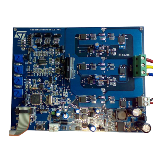
Figure 1.
STEVAL-IHM015V1
Features
■
Voltage range from 5 to 48 V
■
Maximum current up to 25 A
■
Power MOSFET STS8DNH3LL (dual n-channel) 8 A/30 V included
■
Compatible with power MOSFET in SO-8 and DPAK packages
■
10 V auxiliary power supply connector
■
Serial communication interface connector
■
Programming and debug support via a 10-pin ICC connector
■
On-board 2 K-bit (256 bytes) serial memory
■
Four potentiometers for runtime settings
■
Start/stop button
■
Reset button
■
Debug pins available
User manual
based on ST7MC MCU
Rev 2
UM0432
1/53
www.st.com
Advertisement
Table of Contents

Related Manuals for ST STEVAL-IHM015V1


Summary of Contents for ST STEVAL-IHM015V1
- Page 1 Introduction The low-voltage motor control demonstration board (also referred to by its order code STEVAL-IHM015V1) is a complete development platform for low-voltage motor control applications. Based on a cost-effective, flexible and open design, it allows easy demonstration of ST7MC capabilities to drive low-voltage synchronous motors. It includes an ST7MC 8-bit microcontroller with a 16-Kbyte internal Flash memory.
-
Page 2: Table Of Contents
Contents UM0432 Contents System architecture ......... 7 Safety and operating instructions . - Page 3 UM0432 Contents 7.4.6 "3-phase PMAC motor (sinewave)" settings ..... 29 7.4.7 "3-phase PMAC motor (sinewave)" advanced settings ... . . 31 7.4.8 Changing the maximum current allowed by GUI .
- Page 4 Contents UM0432 7.7.4 Setting the potentiometers ........45 7.7.5 Running the motor (LED action) .
- Page 5 UM0432 List of tables List of tables Table 1. ST7FMC2S4T6 functions ..........11 Table 2.
- Page 6 STEVAL-IHM015V1 ........
-
Page 7: System Architecture
A power block that makes a power conversion from the DC bus transferring it into the motor by means of a 3-phase inverter topology. ● The motor itself. The STEVAL-IHM015V1 board can drive the following kinds of motors. – PMDC (or BLAC/BLDC) permanent magnet motors, 6-step current, both in sensored and sensorless mode. -
Page 8: Safety And Operating Instructions
Intended use of the demonstration board The STEVAL-IHM015V1 demonstration board is a component designed for demonstration purposes only, and must not be used for electrical installations or machinery. Technical data and information concerning the power supply conditions are detailed in the documentation and should be strictly observed. -
Page 9: Operating The Demonstration Board
Safety and operating instructions Operating the demonstration board A system architecture that supplies power to the STEVAL-IHM015V1 demonstration board must be equipped with additional control and protective devices in accordance with the applicable safety requirements (for example, compliance with technical equipment and accident prevention rules). -
Page 10: St7Fmc2S4T6 Microcontroller Functions
ST7FMC2S4T6 microcontroller functions UM0432 ST7FMC2S4T6 microcontroller functions Main features ● TQFP44 package. ● 16 Kbyte dual-voltage Flash program memory with read-out protection capability. ● 768 bytes of RAM (256 stacked bytes). ● Clock, reset and supply management with: – enhanced reset system, –... -
Page 11: Table 1
UM0432 ST7FMC2S4T6 microcontroller functions Table 1. ST7FMC2S4T6 functions Function I/o name Description (depends on embedded software) MCO0 PWM outputs high-side phase A MCO1 PWM outputs low-side phase A MCO2 PWM outputs high-side phase B MCO3 PWM outputs low-side phase B MCO4 PWM outputs high-side phase C MCO5... -
Page 12: Sts8Dnh3Ll Characteristics
STS8DNH3LL characteristics UM0432 STS8DNH3LL characteristics The STS8DNH3LL is a dual N-channel power MOSFET in SO-8 package (30 V, 0.018 Ω, 8 A), featuring a low gate charge and STripFET™ III. Figure 3. STS8DNH3LL ● = 30 V = 0.018 Ω ●... -
Page 13: Electrical Characteristics Of The Board
If the measured value is considerably greater than the typical value, some damage has occurred to the board. See the power supply configuration for a 10-V auxiliary supply. Table 3. Electrical characteristics of the control board STEVAL-IHM015V1 Unit Control board parameters 10 V auxiliary supply range – J6 10 V bias current (typical) –... -
Page 14: Board Architecture
Board architecture UM0432 Board architecture The STEVAL-IHM015V1 can be schematized as shown in Figure Figure 4. Board architecture 5V..48V Power Vdriver Supply SENSE PWMs ST7MC Communication User Interface The control board’s core is the ST7MC microcontroller with a dedicated peripheral included to drive the 3-phase brushless motor. -
Page 15: Power Supply
UM0432 Board architecture Power supply The power supply has been designed to address a wide range of DC bus voltages from 5 to 48 V. Three power supply configurations have been implemented. ● Low voltage: 5–6.5 volts based on the L5970 boost converter. ●... -
Page 16: Table 5
Board architecture UM0432 dual devices and power MOSFETs in DPAK package. The board is designed to work up to 25 A and 48 V. Figure 6. Footprint selection of power devices Figure 6 shows one of the three legs of the bridge where it is possible to mount one of the three kinds of devices. -
Page 17: Icc Connector
UM0432 Board architecture Figure 7. Board layout ICC connector The ICC connector (J1) is used to establish ICC communication for programming/debugging purposes. Its pinout is shown in Figure 8. This connector is compatible with Softec’s inDART-STX board (not included in the package). Figure 8. -
Page 18: Sdi Interface (Serial Data Interface)
Board architecture UM0432 SDI interface (serial data interface) The board is provided with an SDI interface (JP1) to establish SCI communication with external devices. We suggest using an isolation board between the SDI interface and the external devices. The pinout is shown in Figure Figure 9. -
Page 19: Board Schematic
UM0432 Board architecture Board schematic Figure 10. Board schematic: control block 19/53 Downloaded from Elcodis.com electronic components distributor... -
Page 20: Figure 11. Board Schematic: Power Block
Board architecture UM0432 Figure 11. Board schematic: power block 20/53 Downloaded from Elcodis.com electronic components distributor... -
Page 21: Motor Control Operations
TRIAC, the isolation constraints still apply for switching semiconductor devices such as MOFSETs.) Note: Isolating the application rather than the oscilloscope is highly recommended in any case. Hardware requirements To set-up the STEVAL-IHM015V1 demonstration board system, the following items are required. ● The board itself: STEVAL-IHM015V1 ●... -
Page 22: Software Requirements
Motor control operations UM0432 Software requirements To customize, compile and download the motor control firmware, the following software must be installed. ● "LV ST7MC - GUI" (included in the CD-ROM). ● STVD7 for inDART-STX V.3.11 (also called "ST7 Toolset" downloadable from Softec’s website: www.softecmicro.com). -
Page 23: Board Setup
UM0432 Motor control operations Figure 12. STVD7 for InDART-STX toolset configuration Board setup 7.4.1 Choosing the right firmware The motor control firmware is arranged according to the kind of motor to be driven and to the driving strategy. See Table 6 to choose which firmware should be used. -
Page 24: Configuring The Firmware Using The Gui
Motor control operations UM0432 7.4.2 Configuring the firmware using the GUI Before actually using the firmware, it must be configured. The term configure indicates the act of selecting a specific driving strategy, such as open or closed loop, voltage or current mode, and so on. -
Page 25: 3-Phase Blac/Dc (Trapezoidal)" Settings
UM0432 Motor control operations Figure 13. Motor Type Choice window You must select the desired value and press OK. 7.4.4 "3-phase BLAC/DC (trapezoidal)" settings Figure 14. "3-phase BLAC/DC (trapezoidal)" basic parameters window 25/53 Downloaded from Elcodis.com electronic components distributor... -
Page 26: Table 8
Motor control operations UM0432 Table 8. "3-phase BLAC/DC (trapezoidal)" basic parameters Parameter name Description Poles pairs Number of pole (north/south) pairs in the motor. Manner in which to run the motor, either open loop (without speed regulation) or closed Speed regulation loop (with speed regulation). -
Page 27: 3-Phase Blac/Dc (Trapezoidal)" Advanced Settings
UM0432 Motor control operations Table 8. "3-phase BLAC/DC (trapezoidal)" basic parameters (continued) Parameter name Description B-emf rising edge B-EMF rising edge delay coefficient value (from 0 to 255). B-emf falling edge B-EMF falling edge delay coefficient value (from 0 to 255). Closed-loop parameter (only in closed loop) Integral coefficient (Ki) Value of the integral coefficient (Ki) of the proportional integrative (PI) regulator. -
Page 28: 3-Phase Blac/Dc (Trapezoidal)" Advanced Parameters
Motor control operations UM0432 Table 9. "3-phase BLAC/DC (trapezoidal)" advanced parameters Parameter name Description Switches PWM frequency Pulse width modulation (PWM) frequency in kHz. Switches PWM minimum off PWM minimum off time in microseconds (µs) to detect the BEMF. time Complementary PWM signal Enables or disables synchronous rectification. -
Page 29: 3-Phase Pmac Motor (Sinewave)" Settings
UM0432 Motor control operations 7.4.6 ”3-phase PMAC motor (sinewave)" settings Figure 16. "3-phase PMAC motor (sinewave)" basic parameters window Table 10. "3-phase PMAC motor (sinewave)" basic parameters Parameter name Description Poles pairs Number of pole (north/south) pairs in the motor. Manner in which to run the motor, either open loop (without speed regulation) or Speed regulation closed loop (with speed regulation). - Page 30 Motor control operations UM0432 Table 10. "3-phase PMAC motor (sinewave)" basic parameters (continued) Parameter name Description Start-up stator frequency Sets the stator frequency during the start-up sequence (only in closed loop). Sets the maximum duration of the start-up sequence in milliseconds (ms) (only in Max duration closed loop).
-
Page 31: 3-Phase Pmac Motor (Sinewave)" Advanced Settings
UM0432 Motor control operations 7.4.7 "3-phase PMAC motor (sinewave)" advanced settings When you click on the Advanced Settings button (see Figure 16), the Advanced Settings dialog box opens (see Figure 17). This is where the advanced "3-phase PMAC motor (sinewave)" motor type parameters are set. Figure 17. -
Page 32: Changing The Maximum Current Allowed By Gui
Motor control operations UM0432 Table 11. "3-phase PMAC motor (sinewave)" advanced parameters (continued) Parameters name Description Voltage level (expressed as a part of the 255 of the bus voltage) of the active braking stator Brake voltage field. Brake min speed Brake stays active until the motor is brought below this rotor frequency. -
Page 33: Programming The Firmware
UM0432 Motor control operations Note: Make sure that the following string: "<firmware name>.elf - 0 error(s), 0 warning(s)" is displayed inside the output pane after the building of the executable. After the building of the executable, ensure that the file "<firmware name>.s19" generated inside the "release"... -
Page 34: Setting The Option Bytes
Motor control operations UM0432 Note: If an error occurs, make sure that the inDART-STX board is connected to the PC. A green LED lights up if the board is connected. Click on File > Load > Code Buffer. In the Load File to Code Buffer dialog box format menu, select "Motorola S-Rec" settings. -
Page 35: Configuring The Dc Input Range
22. This configuration is called a running configuration. Remove the ICC flat cable from the board if present. Connect the insulated DC power supply to the J5 connector of STEVAL-IHM015V1, following the serigraphy for polarity. Connect the phases of the motor to the J10 connector of the board and if required, connect the sensor signal to the hall sensor connector J14. -
Page 36: Changing The Maximum Allowed Bus Voltage Level
Motor control operations UM0432 Figure 22. System setup for running phase 7.4.15 Changing the maximum allowed bus voltage level The board includes an over-voltage protection mechanism that protects the system, preventing the motor from starting if the bus voltage is greater than a given voltage. If this occurs, the red LED starts blinking. -
Page 37: Changing The Maximum Allowed Current Level
UM0432 Motor control operations 7.4.16 Changing the maximum allowed current level An over-current protection mechanism is included inside the board to protect the system, disabling all the power switches if the current that flows inside the motor is greater than a given threshold. -
Page 38: Driving The Bldc Motor (Trapezoidal - Sensorless)
Motor control operations UM0432 Driving the BLDC motor (trapezoidal - sensorless) This section describes how to drive the sensorless brushless permanent magnet motor. You should first check that the board has been set-up for sensorless driving (see Section 7.4.4). 7.5.1 Specific connection (sensor) To also drive the motor in closed-loop mode, it is not necessary that the motor include any position or speed sensor. -
Page 39: Running The Motor (Led Action)
UM0432 Motor control operations During any state: idle, start, run or brake, a blinking red LED together with the brake of the motor indicates a fault condition. A fault condition is due to one of the following: ● hardware overcurrent: current flowing inside the motor reaches a value greater than the maximum allowed current of 7.65 A –... -
Page 40: Stopping The Motor (Led Action)
7.5.9 Detecting the BEMF during the PWM on time The direct back-EMF sensing scheme used by default by the STEVAL-IHM015V1 demonstration board, synchronously samples the motor back-EMF during PWM "off" time without needing to sense or reconstruct the motor’s neutral point in a sensorless BLDC motor drive system. -
Page 41: Detecting The Bemf Using The Internal Reference
UM0432 Motor control operations 7.5.10 Detecting the BEMF using the internal reference First of all, it is necessary to correctly size the value of the R39, R50 and R63 resistors using the following formula. Equation 4 55000 --------------------------------------- - 39 50 63 ⎛... -
Page 42: Driving The Bldc Motor (Trapezoidal - Sensored)
Motor control operations UM0432 Also change the following define in the mtc.h file: #define mem_MCRC_GE ((u8)71) Driving the BLDC motor (trapezoidal - sensored) This section describes how to drive the brushless permanent magnet motor with three hall 60° sensors. First you should check that the board has been set-up for BLDC 60° sensor driving (see Section 7.4.4). -
Page 43: Led Action After Power-On
UM0432 Motor control operations After power-on, the control board’s green LED should blink, signaling that the firmware has started to run. After a while a green LED stays on indicating an "idle" state. 7.6.4 Setting the potentiometers Before running the motor, the three potentiometers P1, P2, P3 must be set (see Table 19 the correct configuration). -
Page 44: Stopping The Motor (Led Action)
Motor control operations UM0432 Table 19. Potentiometer functionality based on open/closed loop driving strategy (continued) Voltage mode Sets the value of the rising delay coefficient from 0 to 255 Sets the value of the falling delay coefficient from 0 to 255 Not used If during the GUI configuration phase the "from RV1"... -
Page 45: Specific Jumper Settings
UM0432 Motor control operations 7.7.2 Specific jumper settings Set-up the board as per the instructions in Section 7.4.12 (bus voltage between 9 and 28 V) Section 7.4.13. Table 21. PMAC SR jumper settings Driving mode Jumper settings J11 open, J12 open, J13 between 2-3 PMAC_3PH_SR J15 open, J16 open, J17 between 2-3 J18 open, J19 open, J20 between 2-3... -
Page 46: Table 22. Potentiometer Functionality Based On An Open-/Closed-Loop Driving Strategy
Motor control operations UM0432 Note: Turning the P3 potentiometer modifies the "phase shift" parameter. To optimize driving, the correct value of this parameter must be set. Finding the optimum value of the "phase shift" can be useful to monitor the DC current provided by the power supply. You should try to fine-tune the P3 potentiometer to minimize current absorption. -
Page 47: Table 23. Bill Of Materials
UM0432 Bill of materials Bill of materials Table 23. Bill of materials Item Reference Part Footprint 1 nF/25 V (NC) smd 0805 100 nF/25 V (NC) smd 0805 1 µF/25 V Through hole C4,C5,C6,C8,C34 10 nF/50 V smd 0805 C7,C9,C10,C11,C21 100 nF/50 V smd 0805 1 nF/50 V (NC) - Page 48 Bill of materials UM0432 Table 23. Bill of materials (continued) Item Reference Part Footprint Vbus-2-WAY screw terminal Through hole +10 V Through hole Phase OUT-3-WAY screw terminal Through hole 5-pin strip-line male Through hole J22,J27 1-pin strip-line male Through hole J23,J24 3-pin strip-line male Through hole...
- Page 49 UM0432 Bill of materials Table 23. Bill of materials (continued) Item Reference Part Footprint R38,R42,R44,R49,R54,R56, 22 kΩ - 1/4 W SMD 1206 R62,R66,R76 22 Ω - 1/4 W R33,R37,R46,R48,R58,R60 SMD 1206 R34,R35,R36,R74,R81 4.7 kΩ - 1/4 W SMD 1206 220 Ω - 1/4 W R40,R51,R61 SMD 1206 R43,R55,R70...
- Page 50 References UM0432 References This user manual provides information on how to use the STEVAL-IHM015V1 and its hardware features. For additional information on supporting software and tools, refer to the following documents. ST7MC datasheet: complete information about microcontroller features and peripherals.
- Page 51 UM0432 Known limitations Known limitations The following are the known limitations present on the STEVAL-IHM015V1 board. ● The filter capacitor for the microcontroller’s power supply is physically situated some distance from the micro pins and near to the start/stop button. Pushing this button generates a glitch on the power supply, which in turn triggers the LVD thus causing an unwanted reset.
-
Page 52: Table 24. Document Revision History
Revision history UM0432 Revision history Table 24. Document revision history Date Revision Changes 24-Jul-2007 Initial release – Changed document title from "Low voltage motor control demo kit" to "Low voltage motor control demonstration board based on ST7MC MCU". – Added Section 7.5.9, Section... - Page 53 No license, express or implied, by estoppel or otherwise, to any intellectual property rights is granted under this document. If any part of this document refers to any third party products or services it shall not be deemed a license grant by ST for the use of such third party products or services, or any intellectual property contained therein or considered as a warranty covering the use in any manner whatsoever of such third party products or services or any intellectual property contained therein.
Need help?
Do you have a question about the STEVAL-IHM015V1 and is the answer not in the manual?
Questions and answers