Table of Contents
Advertisement
Quick Links
November 2008
Downloaded from
Elcodis.com
electronic components distributor
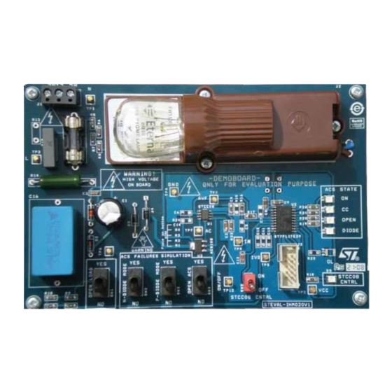
STEVAL-IHM020V1 demonstration board based on the
Introduction
The STEVAL-IHM020V1 demonstration board (see
the performance of the STCC08, which is an AC switch failure mode detector and an AC
power switch driver. The device is dedicated to driving up to 10 mA IGT AC switches (ACS,
ACST and TRIACs), and detecting any switch failures. This solution embeds a switch driver
and an AC switch state detector. It contributes to system safety by monitoring AC switches
driving sensitive loads such as drain pumps, door locks, heaters, cooling fans, and
compressors.
Figure 1.
STEVAL-IHM020V1, STCC08 demonstration board
This user manual provides all information needed to set up and operate the demonstration
board. With this demonstration board, you can:
■
Evaluate the full ST solution (microcontroller + STCC08)
■
Test and analyze the AC switch failure detection features of the STCC08 device
STCC08 AC switch failure mode detector
Figure
Rev 1
UM0583
User manual
1) provides a means to evaluate
AM01336v1
www.st.com
1/23
Advertisement
Table of Contents

Related Manuals for ST STEVAL-IHM020V1


Summary of Contents for ST STEVAL-IHM020V1
-
Page 1: Figure 1. Steval-Ihm020V1, Stcc08 Demonstration Board
This user manual provides all information needed to set up and operate the demonstration board. With this demonstration board, you can: ■ Evaluate the full ST solution (microcontroller + STCC08) ■ Test and analyze the AC switch failure detection features of the STCC08 device... -
Page 2: Table Of Contents
Contents UM0583 Contents Demonstration board introduction ......4 Package contents ..........4 Board presentation . - Page 3 List of figures Figure 1. STEVAL-IHM020V1, STCC08 demonstration board ......1 Figure 2.
-
Page 4: Demonstration Board Introduction
Demonstration board introduction UM0583 Demonstration board introduction Package contents The following items are supplied in this package: ● Demonstration board featuring the STCC08 AC switch failure mode detector ● DVD containing user manual, product presentation and datasheets. Board presentation Figures show the board and the main components used. - Page 5 UM0583 Demonstration board introduction Components on the demonstration board include: ● the STCC08 device (U1) ● the STLITE39F2 MCU (U2). The 8-bit MCU drives the AC switch through the STCC08, analyzes the STCC08 AVF signals and powers LEDs to indicate AC switch failures ●...
-
Page 6: Stcc08 Description
STCC08 description UM0583 STCC08 description Block diagram description Figure 4 shows the block diagram of the STCC08. It includes a “gate driver” block to control the AC switch, a “power switch signal shaping” block used to read the AC switch state and a buffer able to send the AC switch state to the MCU (AVF DRIVER). -
Page 7: Gate Driver
UM0583 STCC08 description Table 1. STCC08 pin definition Symbol Type Description Signal AC switch drive Signal Alternating voltage feedback: AC switch state output Not connected Signal AC switch state sense input Power Positive power supply Signal AC switch gate driver output Signal AC switch gate current setting Power... -
Page 8: Figure 6. Ac Switch Failure-Detection Principle
STCC08 description UM0583 Figure 6. AC switch failure-detection principle Load Load VCC/COM VCC/COM STCC08 STCC08 Load Load AC switch AC switch Line Line Load Load RShunt RShunt ACS state: OFF if IN=0 (GND) or failed in open circuit if IN=1 (VCC) Load Load VCC/COM... - Page 9 UM0583 STCC08 description Table 2 gives the AC switch state according to the AVF signal and the MCU control (IN). Knowing the IN signal state, the MCU is able to define the AC switch state by analyzing the AVF signal. According to the failure mode, the MCU can place the system in a safe configuration by switching off the home appliance front-end relay.
-
Page 10: Features
Features UM0583 Features ST7LITE39F2 microcontroller The 8-bit MCU used in this board is the ST7LITE39F2. It belongs to the ST7 family of microcontrollers, and offers a large number of features at minimum cost. ● The peripheral hardware requirements are reduced to a minimum: –... - Page 11 UM0583 Features temperatures, please refer to application note AN2716 to redefine the R resistor, and STCC08 consumption to redefine the C16 capacitor value. To reduce the surge current when the board is powered, a 39 Ω R14 resistor is connected in series with the C16 capacitor.
-
Page 12: Using The Demonstration Board
Using the demonstration board UM0583 Using the demonstration board Load The ACS included in the board can withstand a 0.8 A RMS permanent current up to an ambient temperature of 80 °C. The switch can drive common washing-machine AC loads without difficulty. -
Page 13: Getting Started
UM0583 Using the demonstration board Getting started Warning: The demonstration board is not electrically isolated from the AC input. The MCU is directly linked to the mains voltage. No insulation is ensured between the accessible parts and the high voltage. The STCC08 demonstration board must be used with care and only by persons qualified to work with electricity at mains voltage levels. - Page 14 Using the demonstration board UM0583 ● To operate the STCC08 board correctly and at each test, perform the following procedure first: – Place the “STCC08 CNTRL” switch (SW5) to the “OFF” position – Set the “N DIODE MODE (SW2)” and “P DIODE MODE (SW3)” switches to the “NO”...
-
Page 15: Figure 9. Short-Circuit Detection
UM0583 Using the demonstration board Figure 9. Short-circuit detection AC Line Load AM01344v1 Figure 10. Diode mode detection AC Line Load AM01345v1 Figure 11. Open circuit detection AC Line Load AM01346v1 15/23 Downloaded from Elcodis.com electronic components distributor... -
Page 16: Iec 61000-4-4 Burst Immunity Test
IEC 61000-4-4 Burst immunity test UM0583 IEC 61000-4-4 Burst immunity test Test conditions ● Ambient temperature: 25 °C ● Relative humidity: 35% ● Test performed in accordance with IEC 61000-4-4 Demonstration board immunity test The AC line input X2 capacitor C15 (10 nF) is used to help avoid triggering the AC switch (ACS108-6S). - Page 17 UM0583 IEC 61000-4-4 Burst immunity test data. This maintains the previous switch state, for example, when a RESET occurs due to an EMI problem. If, when checked, the RAM registers are not as expected, a complete initialization procedure is launched. If the RAM area is adequate, then a “smart reset”...
-
Page 18: Conclusion
Show how to connect the STCC08 to an MCU (non-insulated version) ● Give the user the opportunity to evaluate a full ST solution (microcontroller + STCC08). This user manual is intended to help home appliance designers test and evaluate the STCC08 AC switch failure mode detector using the demonstration board. -
Page 19: Appendix Astcc08 Demonstration Board Schematic
UM0583 STCC08 demonstration board schematic Appendix A STCC08 demonstration board schematic Figure 13. STEVAL-IHM020V1 demonstration board schematic diagram AM01347v1 19/23 Downloaded from Elcodis.com electronic components distributor... -
Page 20: Appendix B Bill Of Materials
Bill of materials UM0583 Appendix B Bill of materials Table 5. Bill of material Tolerance Voltage/ Technology Ref. Part/value Watts Package footprint current information STCC08 SO-8 ST7LITE39FM6 SO-20 ACS108-6S SOT 223 R1, R2, R3, R4, R5, R6, 56 kΩ 1/4 W SMD 1206 R7, R8 R9, R10, R11,... - Page 21 UM0583 Bill of materials Table 5. Bill of material (continued) Tolerance Voltage/ Technology Ref. Part/value Watts Package footprint current information LIGHT BULB - 15 W at 15 W 230 V Female connector HE10 - 2x5 250 V/ Fuse SW1, SW2, Switch 250 V SW3, SW4...
- Page 22 Revision history UM0583 Revision history Table 6. Document revision history Date Revision Changes 12-Nov-2008 Initial release 22/23 Downloaded from Elcodis.com electronic components distributor...
- Page 23 No license, express or implied, by estoppel or otherwise, to any intellectual property rights is granted under this document. If any part of this document refers to any third party products or services it shall not be deemed a license grant by ST for the use of such third party products or services, or any intellectual property contained therein or considered as a warranty covering the use in any manner whatsoever of such third party products or services or any intellectual property contained therein.
Need help?
Do you have a question about the STEVAL-IHM020V1 and is the answer not in the manual?
Questions and answers