KaVo ORTHOPANTOMOGRAPH OP 3D User Manual
Hide thumbs
Also See for ORTHOPANTOMOGRAPH OP 3D:
- User and installation manual (221 pages) ,
- Service manual (159 pages) ,
- Installation manual (40 pages)

Related Manuals for KaVo ORTHOPANTOMOGRAPH OP 3D


Summary of Contents for KaVo ORTHOPANTOMOGRAPH OP 3D
- Page 1 ™ ORTHOPANTOMOGRAPH OP 3D User Manual 212972 rev. 30 | 0.805.4913 ENGLISH Dental Excellence...
-
Page 3: Table Of Contents
Contents 1 Disclaimer..........................5 2 Introduction........................6 ™ 2.1 ORTHOPANTOMOGRAPH OP 3D......................6 2.2 Intended use..............................7 2.3 Intended user profile............................ 7 2.4 Associated documentation......................... 7 2.5 Abbreviations..............................7 2.6 Signal words..............................8 2.7 Disposal and recycling..........................8 2.8 Warnings and requirements........................9 2.8.1 Warnings and precautions for use....................9 2.8.2 Connection requirements......................10 2.8.3 Device modifications........................10 3 Overview........................... 11 3.1 Main parts............................... - Page 4 6.3 Preparing the device for imaging......................50 6.4 Patient positioning............................. 52 6.4.1 Patient positioning for Panoramic imaging................. 52 6.4.2 Patient positioning for Cephalometric imaging..............57 6.4.3 Patient positioning for Carpus imaging................61 6.4.4 Patient positioning for 3D imaging..................63 6.5 Taking an image............................67 6.5.1 Taking Panoramic and Cephalometric images..............67 6.5.2 Taking Scout and 3D images....................68 6.5.3 Taking Dental cast images.......................
-
Page 5: 1 Disclaimer
The original language of this manual is English. PaloDEx Group Oy reserves the right to make changes in specification and features shown herein, or discontinue the product described at any time without notice or obligation. Contact your KaVo Kerr representative for the most current information. -
Page 6: 2 Introduction
2 Introduction 2 Introduction ™ 2.1 ORTHOPANTOMOGRAPH OP 3D ™ The ORTHOPANTOMOGRAPH OP 3D (later called device) is a dental X-ray device producing high quality digital images of dentition, TM-joints, head and neck area and carpus. To take images, you need a suitable workstation connected to the device and a dental imaging software to capture and manage the images. -
Page 7: Intended Use
2 Introduction requirements in the USA. The workstation must conform to all the device and dental imaging software requirements. 2.2 Intended use ™ ORTHOPANTOMOGRAPH OP 3D is an X-ray device that is intended to be used for imaging of adult and pediatric patients. -
Page 8: Signal Words
2 Introduction Frankfort-Horizontal Graphical User Interface Dose Area Product ™ Low Dose Technology Metal Artifact Reduction. Reduces the effect of metal and other dense radiopaque objects, that typically create artifacts which are seen as stripes and shadows. Quality Control ALARA As Low As Reasonably Achievable Medical Device Directive 93/42/EEC CBCT Cone Beam Computed Tomography... -
Page 9: Warnings And Requirements
2 Introduction 2.8 Warnings and requirements 2.8.1 Warnings and precautions for use • Before using the device for the first time, familiarize yourself with this manual to ensure the safe use of the device. • Before using the device for the first time, ensure that it has been set up according to your requirements. -
Page 10: Connection Requirements
2 Introduction 2.8.2 Connection requirements NOTICE! Always follow local and national requirements regarding the connection of medical systems. NOTICE! The workstation firewall or antivirus software may cause unexpected issues to IP traffic and system performance. • A network connection between the device and the acquisition workstation is required for the device to be used. -
Page 11: 3 Overview
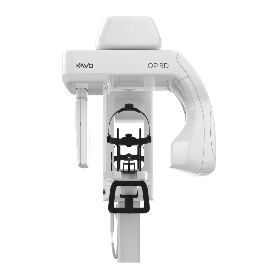
3 Overview 3 Overview 3.1 Main parts MAIN DEVICE 1. Column 2. Carriage 3. Upper shelf 4. Rotating unit 5. Sensor (2D/3D)* 6. Sensor (2D)* 7. PAN/3D Tubehead 8. Patient positioning panel 9. Status indicator light 10. Power switch (Back of the 11. -
Page 12: Patient Positioning Lights
3 Overview 3.2 Patient positioning lights NOTICE! Appropriate lights are turned on automatically, based on the selected modality, program and FOV. 3.2.1 Positioning light locations A. Tilt light (PAN imaging) B. Midsagittal light C. Horizontal light; top of FOV / FH light D. -
Page 13: Cephalometric Lights
3 Overview 3.2.3 Cephalometric lights E. FH (Frankfort-Horizontal) light NOTICE! Lateral programs only. 3.2.4 3D lights B. Midsagittal light C. Horizontal light, top of FOV D. Horizontal light, bottom of FOV NOTICE! The position of the top of FOV light is automatically adjusted according to the selected FOV. -
Page 14: Accessories
3 Overview 3.3 Accessories Chin Rest Bite Block Lip Support Head Support with a detachable strap Carpus holder (optional) Disposable covers for patient positioning accessories: • Disposable covers for Bite Block • Disposable covers for Lip Support • Disposable cover sheets for Chin Rest and Head Support •... -
Page 15: Other Detachable Parts
3 Overview 3.4 Other detachable parts CALIBRATION TOOLS: Geometry calibration phantom CEPH calibration rod (CEPH only) 3D QUALITY CONTROL TOOLS: 3D QC phantom 3D QC phantom holder 2D QUALITY CONTROL TOOLS (OPTIONAL): 2D QC test phantom Copper filter - 0.8 mm/1.8 mm PAN QC phantom holder CEPH QC phantom holder ™... -
Page 16: Emergency Stop Switch
3 Overview DENTAL CAST IMAGING TOOLS (OPTIONAL): Dental cast holder 3.5 Emergency stop switch An emergency stop switch is located on the left side of the carriage. Pressing the emergency stop switch immediately terminates the imaging and all device movements. NOTICE! An interrupted imaging process cannot be resumed. A new image needs to be taken. To release the emergency stop switch, rotate it clockwise. -
Page 17: Device Connectors
3 Overview 3.6 Device connectors The device connectors are located at the rear of the device, under the back panel cover. Power cord Ethernet cable for workstation connection Exposure button connector Remote exposure switch connector (optional) External warning light connector (optional) Main fuses F1+F2 (10 A fuses pre-installed) External warning light fuse F3 (2 A fuse pre-installed) Control interface... -
Page 18: 4 User Interfaces
4 User interfaces 4 User interfaces 4.1 Graphical User Interface (GUI) 4.1.1 GUI Overview Patient name and identification. Selection of imaging modality, PAN, CEPH, 3D or CAST. Selection of imaging program and imaging program settings. Main view area. Shows a dental chart for the selected modality and previews of the taken images. Selection of imaging parameters. - Page 19 4 User interfaces IMAGING PROGRAM SETTINGS: Test mode Indicates if Test mode is active. Press Test mode icon to enable/disable device radiation production. Test mode can be used for example to demonstrate the device movements. You can also use the patient positioning panel to enable/disable the Test mode.
-
Page 20: Panoramic View
4 User interfaces 4.1.2 Panoramic view 4.1.2.1 Panoramic imaging program selection ™ ORTHOselect panoramic dental chart Dental chart shows which segments of the dentition are imaged with the selected imaging program. You can also manually select which segments of the dentition are imaged. Press the segments to select (green) and deselect (gray) them. - Page 21 4 User interfaces ™ 4.1.2.2 QUICKcompose panoramic image preview NOTICE! Image previews are not shown in full resolution on GUI. Zoom slider You can zoom the preview image in/out using the zoom slider. While zoomed in, you can click and drag to scroll the image. Brightness slider You can adjust the brightness of the shown preview image using the brightness slider.
-
Page 22: Cephalometric View
4 User interfaces 4.1.3 Cephalometric view 4.1.3.1 Cephalometric imaging program selection ™ ORTHOselect cephalometric view The cephalometric view shows which parts of the skull are imaged with the selected imaging program. In lateral imaging, the image field width can be manually adjusted by dragging the slider control. - Page 23 4 User interfaces Cephalometric imaging programs Indicates which imaging program is selected. Press the imaging program icons to change the active imaging program; Lateral Pediatric lateral PA projection Carpus view projection projection NOTICE! The carpus view program requires an optional carpus holder.
- Page 24 4 User interfaces ™ 4.1.3.2 QUICKcompose cephalometric image preview NOTICE! Image previews are not shown in full resolution on GUI. Zoom slider You can zoom the preview image in/out using the zoom slider. While zoomed in, you can click and drag to scroll the image. Brightness slider You can adjust the brightness of the shown preview image using the brightness slider.
-
Page 25: View
4 User interfaces 4.1.4 3D view 4.1.4.1 3D imaging program selection ™ ORTHOselect dental chart Dental chart is used to select the Region of Interest (ROI) for the 3D scan. The FOV changes automatically according to the selections. Press teeth, jaw and TMJ icons to select which parts of the dentition are studied: •... - Page 26 4 User interfaces FOV size Indicates the currently selected FOV size (H x D). Press the FOV size icon to open a list of the available 3D FOV sizes; 5 x 5, 6 x 8, 6 x 9, 8 x 8, 9 x 11 and 9 x 14. Press on the listed FOV size icon to activate it.
- Page 27 4 User interfaces Scout image program Indicates if the Scout image program is active. A Scout image is taken to verify and perform adjustment to the FOV position and height before initiating a full 3D scan. By default, the Scout image is always active when taking 3D images.
- Page 28 4 User interfaces FOV position adjustment You can adjust the position of the FOV, according to the scout image, by sliding the adjustment icons left or right on the scale. The left slider adjusts the FOV position in Posterior (P) - Anterior (A) direction and the right slider in Left (L) - Right (R) direction.
- Page 29 4 User interfaces ™ 4.1.4.3 QUICKcompose 3D image preview NOTICE! Image previews are not shown in full resolution on GUI. NOTICE! The image has indications from which direction the image is shown; A/P (Anterior/ Posterior), L/R (Left/Right) and H/F (Head/Foot). Preview projection Indicates which preview projection is selected.
- Page 30 4 User interfaces Volume preview Shows a preview of the 3D volume. You can rotate the preview using the slider on the right side of the image. Brightness slider You can adjust the brightness of the shown preview image using the brightness slider.
-
Page 31: Dental Cast View
4 User interfaces 4.1.5 Dental cast view NOTICE! This is an optional, separately activated imaging modality. 4.1.5.1 Dental cast program selection Image resolution Indicates the currently selected resolution. Press the image resolution selection icon to open a list of available image resolutions;... - Page 32 4 User interfaces ™ 4.1.5.2 SMARTVIEW 2.0 scout image view The green rectangle on the scout image represents the imaged FOV. You can adjust the FOV size and position to suit your imaging needs. FOV height adjustment You can adjust the height of the FOV, according the scout image, by sliding the height adjustment icon up or down.
- Page 33 4 User interfaces OK button Press OK button to approve the changes made to the FOV location and size using the Scout image and to proceed to the 3D exposure. ™ 4.1.5.3 QUICKcompose dental cast image preview NOTICE! Image previews are not shown in full resolution on GUI. NOTICE! The image has indications from which direction the image is shown;...
- Page 34 4 User interfaces Volume preview Shows a preview of the 3D volume. You can rotate the preview using the slider on the right side of the image. Brightness slider You can adjust the brightness of the shown preview image using the brightness slider.
-
Page 35: Device Settings
4 User interfaces 4.1.6 Device settings QUALITY CONTROL Shows a list of quality control (QC) programs, their completion status and last completion date. See chapter Quality control on page 77 for more information on how to take quality control images. CALIBRATIONS Shows a list of user performable device calibrations, their completion status and last completion date. - Page 36 4 User interfaces SETTINGS Device settings: Friendly name Set a name for the device, which is shown next to the device settings icon and on the imaging software. 3D Metal Artefact Enable or disable MAR, Metal Artefact Reduction. MAR is used to Reduction reduce the effect of metals and other dense radiopaque objects on the 3D image.
- Page 37 4 User interfaces Time zone Set the timezone to match the installation location. To change the time zone, start to write the continent, capitol or state (US) and select the correct selection from the drop down list. Patient size settings: Adjust the default mA and kV values for medium size patient preset. Other patient size selections are changed relatively to the adjustment made.
- Page 38 4 User interfaces ABOUT Software versions Shows the serial numbers of: • The main device • Sensors • Tubehead assemblies Shows also the versions of the installed firmware and hardware. Notices Legal information and terms and conditions for use. Exposure counters Shows the amount of exposures taken with the device.
-
Page 39: Patient Positioning Panel
4 User interfaces 4.2 Patient positioning panel Carriage up/down slider. The carriage can be driven up and down by sliding a finger on the carriage up/down slider. The finger movement detection works best when using the entire finger tip or two fingers side by side. -
Page 40: Status Indicator Light
4 User interfaces 4.3 Status indicator light Device status indicator light, located on the top of the carriage, illuminates according the device status: • YELLOW: Device is generating X-rays. • BLUE: Device is in error state or pending user action. Check the GUI for details. •... -
Page 41: 5 Imaging Programs
5 Imaging programs 5 Imaging programs 5.1 Panoramic programs NOTICE! The image field dimensions and segment widths and height differences shown here are for illustrative purposes only. Standard Panoramic imaging program The Standard Panoramic imaging program provides general view of dental and facial anatomy based on panoramic imaging technique. - Page 42 5 Imaging programs Bitewing program A bitewing view of the patient's Premolar-Molar region dentition. You can choose to image both or only other segment in single scan. Press the segments on the dental chart to deselect and select them. TMJ, lateral projection Lateral TMJ program provides a lateral view of the patient's left and right temporomandibular joints.
-
Page 43: Cephalometric Programs
5 Imaging programs 5.2 Cephalometric programs NOTICE! These programs are available only for cephalometric devices. Cephalometric programs provide projection images of patient skull and dental anatomy. Images are utilized in orthodontics and general diagnostics. NOTICE! The image field dimensions shown here are for illustrative purposes only. Cephalometric lateral projection The lateral projection uses a full height image field that provides a nearly full skull image. - Page 44 5 Imaging programs Cephalometric Posterior-Anterior (PA) projection PA projection imaging can be used, for example, to identify any facial asymmetries, dentoalveolar asymmetries, dental crossbite and mandibular displacement. In PA projections, the patient faces away from the tubehead to keep the radiation dose to patient's eyes in minimal level.
-
Page 45: Programs
5 Imaging programs 5.3 3D programs NOTICE! These programs are available only for 3D devices. Always select the smallest feasible FOV size, resolution and imaging parameters for the 3D image in order to follow the ALARA (As Low As Reasonably Achievable) principle. NOTICE! It is always up to the dental professional to select the appropriate FOV, resolution and imaging parameters. - Page 46 5 Imaging programs FOV 6 x 8 Optimized for multiple implant placement using surgical guides, imaging the whole dental arc of one jaw, 3rd molar visualization, pathology (bilateral analysis) and periodontal cases. Available resolutions: LDT resolution Standard resolution High resolution FOV 6 x 9 Optimized for multiple implant placement using surgical guides, imaging the whole dental arc of one jaw, 3rd molar visualization, pathology (bilateral analysis) and periodontal cases.
-
Page 47: Resolutions
5 Imaging programs FOV 9 x 11 Optimized for imaging the entire dentition, both mandibula and maxilla, maxillary sinuses, jaws with bilateral joints and jaws with airways. Available resolutions: LDT resolution Standard resolution High resolution FOV 9 x 14 Optimized for imaging the entire dentition, both mandibula and maxilla, including airway and upper cervical spine or the sinus, maxillary sinuses, jaws with bilateral joints, jaws with airways, analyses of both TMJs and for maxillofacial surgeries. -
Page 48: Dental Cast Program
5 Imaging programs 5.4 Dental cast program The dental cast program is initially taken with FOV 9 x 11. The height of the FOV can be adjusted after scout image. Available resolutions: LDT resolution Standard resolution High resolution ™ ORTHOPANTOMOGRAPH OP 3D... -
Page 49: 6 Using The Device
6 Using the device 6 Using the device 6.1 General imaging workflow ™ ORTHOPANTOMOGRAPH OP 3D... -
Page 50: Powering On The Device
6 Using the device 6.2 Powering on the device Power the device on. Power switch is located at the rear of the carriage. The device starts initialization. Complete the device initialization by pressing the HOME button on the patient positioning panel when indicator light starts blinking in blue. - Page 51 6 Using the device GUI: Select the imaging modality, imaging program and patient size to set up the device. If the preset selections are not suitable for the patient, adjust the imaging parameters manually. Imaging modality CEPH Imaging program Patient size Imaging parameters NOTICE! Exercise special care when imaging patients outside the typical adult size range, especially smaller pediatric patients.
-
Page 52: Patient Positioning
6 Using the device 6.4 Patient positioning 6.4.1 Patient positioning for Panoramic imaging NOTICE! The device can be used to take images of both standing and seated patients. It is recommended to have very tall patients seated for easier positioning. Press HOME button on the patient positioning panel. The device moves to HOME (Patient-In) position. - Page 53 6 Using the device Select the patient positioning accessory according to the image to be taken, attach it to the chin rest and place them on the lower shelf of the device, as shown below. Standard and Pediatric Standard and Pediatric TMJ imaging panoramic and Bitewing panoramic and...
- Page 54 6 Using the device Tell the patient to remove their glasses, hearing aids, removable dentures, jewellery, hair clips and all other things that can cause artifacts to the image. Protect the patient from radiation according to the local regulations, for example with a lead apron and a thyroid shield.
- Page 55 6 Using the device BITEWING IMAGING: • The patient’s occlusal plane should be horizontal and parallel to the FH light. TMJ IMAGING: • The patient’s Frankfort-Horizontal plane should be close to parallel to the horizontal light. The FH light indicates the center of the field. You can take a TMJ image with the patient's mouth closed or open.
- Page 56 6 Using the device 15. Close the temple supports against the patients head and close the locking lever to lock the head support in place. 16. Ask the patient to close their lips and press their tongue against the palate if possible. ™...
-
Page 57: Patient Positioning For Cephalometric Imaging
6 Using the device 6.4.2 Patient positioning for Cephalometric imaging NOTICE! The device can be used to take images of both standing and seated patients. It is recommended to have very tall patients seated for easier positioning. Press HOME button on the patient positioning panel. The device moves to CEPH HOME (Patient-In) position. - Page 58 6 Using the device Adjust the device's height to approximately match the patient's height by sliding a finger on the carriage up/down slider. Tell the patient to remove their glasses, hearing aids, removable dentures, jewellery, hair clips and all other things that can cause artifacts to the image. Protect the patient from radiation according to the local regulations, for example with a lead apron and a thyroid shield.
- Page 59 6 Using the device 13. Adjust the patient's head position/orientation. NOTICE! To ensure optimal image quality, pay attention to the correct patient positioning. LATERAL PROJECTION: • The patient's Frankfort-Horizontal plane should be horizontal. Use the FH light as a guide. PA PROJECTION: •...
- Page 60 6 Using the device PA WATERS PROJECTION: • Turn the patient's head upwards until the angle between the patient’s Frankfort-Horizontal plane and the horizontal plane is around 35-40°. NOTICE! The horizontal light is not lit for PA projections. 14. Turn the nasion support down and slide it against the patient's nasion when taking Lateral projections.
-
Page 61: Patient Positioning For Carpus Imaging
6 Using the device 6.4.3 Patient positioning for Carpus imaging The Carpus imaging program requires a special carpus holder (optional) to be used. CAUTION! Before taking a Carpus image, make sure the imaging method is approved by local authorities. Press HOME button on the patient positioning panel. The device moves to CEPH HOME (Patient-In) position. - Page 62 6 Using the device Attach the carpus holder by sliding it to the base of the nasion support. Adjust the device's height if needed. Ask the patient to remove any jewellery and all other things that may cause artifacts to the image. Protect the patient from radiation according to the local regulations, for example using a lead apron.
-
Page 63: Patient Positioning For 3D Imaging
6 Using the device 6.4.4 Patient positioning for 3D imaging NOTICE! The device can be used to take images of both standing and seated patients. It is recommended to have very tall patients seated for easier positioning. Press HOME button on the patient positioning panel. The device moves to HOME (Patient-In) position. - Page 64 6 Using the device Adjust the device's height to approximately match the patient's height by sliding a finger on the carriage up/down slider. Open the head support locking lever on the lower shelf, push the head support towards the mirror and lock it leaning forward. Tell the patient to remove their glasses, hearing aids, removable dentures, jewellery, hair clips and all other things that can cause artifacts to the image.
- Page 65 6 Using the device 12. Fine adjust the device's height and adjust patient's head position/orientation using the patient positioning lights as guides. NOTICE! To ensure optimal image quality, pay attention to the correct patient positioning. NOTICE! You can open the mirror and use it to help in positioning the patient. Close the mirror before you start the imaging.
- Page 66 6 Using the device 16. Lower the head support strap behind patient's head and tighten it to minimize the patient movement. ™ ORTHOPANTOMOGRAPH OP 3D...
-
Page 67: Taking An Image
6 Using the device 6.5 Taking an image NOTICE! If the patient is feeling insecure or has an exceptional anatomy, use the Test mode to demonstrate the unit movements and to make sure that the rotating unit does not collide with the patient during the imaging process. Activate the Test mode from the GUI or the patient positioning panel and then press and hold the exposure button. -
Page 68: Taking Scout And 3D Images
6 Using the device 6.5.2 Taking Scout and 3D images NOTICE! It's recommended to have Scout mode enabled by default. If you do not wish to take a Scout image, deactivate the selection from the GUI. Ensure the correct patient positioning, imaging program selection and that the device is in Ready state with the indicator light turned green. -
Page 69: Taking Dental Cast Images
6 Using the device 16. Acknowledge the preview by pressing the OK button. 17. Continue to take the next image, if multiple images need to be taken. 18. Release the patient from the device. 19. Remove all disposable covers and decontaminate the device and the patient positioning accessories. -
Page 70: 7 Maintenance
7 Maintenance 7 Maintenance The maintenance and calibration procedure intervals described here are minimum requirements and recommendations. The maintenance and calibration procedures can be made more frequent and stringent to comply with local regulations regarding the use and maintenance of dental X-ray devices. 7.1 Cleaning and decontamination NOTICE! Decontamination techniques for the device, its accessories and the room must comply with all laws and regulations within the local jurisdiction. -
Page 71: Calibrations For The User
7 Maintenance 7.2 Calibrations for the user 7.2.1 When to calibrate the device The device must be calibrated and, if necessary, adjusted at regular intervals in accordance with the national regulations regarding the use, maintenance and service of dental X-ray devices. NOTICE! The device has multiple calibration programs, but only the ones listed in this chapter are meant to be performed by the user. - Page 72 7 Maintenance A list of available device calibrations is shown with the status of the calibration. NOTICE! The calibration programs listed on the GUI depend on the device configuration. Calibration status indications: Calibration not performed or Recalibration is required. Calibration performed failed.
-
Page 73: Calibration Procedure
7 Maintenance 7.2.3 Calibration procedure NOTICE! Some calibrations in this chapter are not available with all device configurations. Perform the calibrations in the exact order as shown on the GUI. After you have run all available calibrations successfully, take quality control images as instructed in chapter Quality control on page 77. - Page 74 7 Maintenance Press and hold the exposure button down to take the calibration image. When the exposure warning stops and the program end tone is played, the program is complete. The calibration image appears on the GUI. Acknowledge the calibration result by pressing the OK button. ™...
- Page 75 7 Maintenance 7.2.3.3 3D geometry calibrations These programs create the calibration data for reconstructing 3D images. NOTICE! This calibration produces X-rays. Protect yourself from radiation. NOTICE! The list of available calibrations depend on the device configuration and country specification. Perform the calibrations in this order, the instructions are the same for all programs: •...
- Page 76 7 Maintenance 7.2.3.4 PAN pixel calibration (2D sensor) This program calibrates the 2D sensor for Panoramic imaging. No calibration tools are required when performing this calibration. NOTICE! This calibration produces X-rays. Protect yourself from radiation. Select PAN pixel calibration (2D sensor) from the Calibrations menu. Protect yourself from radiation.
-
Page 77: Quality Control
7 Maintenance The calibration image appears on the GUI. Acknowledge the calibration result by pressing the OK button. 7.3 Quality control The quality control (QC) programs in the Quality control menu are used to ensure that the image quality remains constant. Quality control should be performed at regular intervals, preferably at least once a month and always after calibration. - Page 78 7 Maintenance Attach the PAN QC phantom holder and 2D QC test phantom to the device. Attach the copper filter in front of the radiation window on the PAN/3D tubehead. The filter attaches in place with magnets. Protect yourself from radiation. Press and hold the exposure button down to take the QC image.
- Page 79 7 Maintenance Workstation: Visually evaluate the image using the dental imaging software: A: Smoothness of the exposed area. B: Non-exposed area surrounds the whole image. C: High contrast resolution; the distinguishable line pair resolution should be: • 3.1 LP/mm or better when using 0.8mm Copper filter •...
-
Page 80: Ceph Qc
7 Maintenance 7.3.2 CEPH QC NOTICE! This program is available only for devices with cephalometric (CEPH) modality. NOTICE! The CEPH QC is an optional, yet recommendable, procedure and is mandatory to be performed where local regulations require it. GUI: Go to device settings. GUI: Select CEPH QC program from the Quality control menu. - Page 81 7 Maintenance If required by the local regulations, attach the copper filter in front of the radiation window on the CEPH tubehead. The filter attaches in place with magnets. Protect yourself from radiation. Press and hold the exposure button down to take the QC image. 10.
- Page 82 7 Maintenance 15. Detach the copper filter from the CEPH tubehead if it was used. 7.3.3 3D QC NOTICE! This program is available only for devices with 3D modality. GUI: Go to device settings. GUI: Select 3D QC program from the Quality control menu. Attach the 3D QC phantom holder and the 3D QC phantom to the device.
- Page 83 7 Maintenance Workstation: Visually evaluate and inspect the 3D image for visual defects such as artifacts using the 3D imaging software. NOTICE! The device determines if the QC image is PASSED or FAILED according to measured data, not based on the visible image quality. NOTICE! You should also compare the new QC image to the reference image taken during the installation or the latest service.
-
Page 84: Annual Maintenance
7 Maintenance 7.4 Annual maintenance An authorized service technician must carry out a full inspection of the device once a year. The following checks must be carried out during the inspection: • Check that the mains cord is not damaged in any way. •... -
Page 85: 8 Troubleshooting
8 Troubleshooting 8 Troubleshooting Problem Possible cause Solution Image is not transferred to the Local network connection is The device stores the latest workstation. disrupted, which causes loss of image until a confirmation of data. a successful transfer to the workstation is received. Re- establish the local network connection and the image data is transferred automatically. - Page 86 8 Troubleshooting Problem Possible cause Solution GUI shows a message "Detach Issue in CEPH head support Recalibrate the CEPH head carpus holder" even though the calibration. support (service technician carpus holder is not attached. only). ™ ORTHOPANTOMOGRAPH OP 3D...
-
Page 87: 9 Technical Data
9 Technical data 9 Technical data 9.1 Technical specifications General information Manufacturer: PaloDEx Group Oy Nahkelantie 160, FI–04300 Tuusula, FINLAND Quality system In accordance with ISO13485 standard Environmental management system In accordance with ISO14001 standard Conformity to standards: IEC60601–1 (ed.3)+Am1 IEC60601–1–3: (ed.2)+Am1 IEC60601–1–6 (ed.3.1) IEC60601–1–9 (ed.1) IEC60601–2–28 (ed.2) - Page 88 9 Technical data Device data Model: PCX–1 Protection against electric shock Class I Degree of protection Type B applied with no conductive connection to the patient Protection against the ingress of liquids IP20 Cleaning agents and protection against • Distilled water cross contamination •...
- Page 89 9 Technical data Electrical connections Nominal mains voltage 100 - 240 VAC Tolerance: ± 10% Input power frequency 50 / 60 Hz Nominal current 10 A @ 220–240 VAC, 15 A @ 100 – 120 VAC Main fuses (F1 & F2) 220–240 VAC: Littelfuse 215 (Time–Lag) 10 A Cooper Bussman (Time Delay) S505H–10–R...
- Page 90 9 Technical data 2D/3D image detector Technology / Sensor type CMOS Image receptor area 147 x 112 mm / 5.78 x 4.4 in max. 147 mm 2D image detector Technology / Sensor type CMOS Image receptor area PAN: 152 x 6 mm / 6 x 0.2 in CEPH: 228 x 6 mm / 8.8 x 0.2 in max.
- Page 91 9 Technical data Main device package Package dimensions (L x W x H) 1220 x 770 x 1100 mm 48 x 30.3 x 43.3 in Package weight 179 kg / 395 lbs Package material weight Pallet: 17 kg / 37 lbs Plywood: 11 kg / 24.3 lbs Cardboard: 10 kg / 22 lbs Metal supports: 11 kg / 24.3 lbs...
- Page 92 9 Technical data Ambient temperatures Transportation and storage -25 – +55°C Operation Temperature +10 – +35°C RH 30–80% Atmospheric pressure 70 – 106 kPa ™ ORTHOPANTOMOGRAPH OP 3D...
-
Page 93: Imaging Program Specifications
9 Technical data 9.2 Imaging program specifications NOTICE! Device's radiation dose production vary from unit to unit. Radiation dose production, shown on the GUI, is calculated by scaling a measured reference dose production value with the selected imaging program technical factors and DAP correction factor. Air KERMA production can be calculated by dividing the provided DAP value with the active sensor area. -
Page 94: Programs
9 Technical data Carpus program & technical factors Magnification factor: 1.05 Program Field of Field of kV range mA range Exposure time view width view height Carpus view 200 mm 223 mm 60 - 73 kV 2.0 - 12.5 mA 8.1 s 7.9 in 8.9 in 9.2.3 3D programs... -
Page 95: Patient Size Setting Default Values
9 Technical data 3D imaging programs & technical factors FOV size Resolution Voxel size mA range Exposure time 5 x 5 280 μm 2.0 - 4.0 mA 1.4 - 1.5 s Standard 200 μm 4.0 - 12.5 mA 2.9 - 3.1 s High 125 μm 2.0 - 4.0 mA... -
Page 96: Patient Contacting Parts
9 Technical data Panoramic programs using 2D sensor Small Medium Large 66 kV / 5.0 mA 66 kV / 7.1 mA 73 kV / 9.0 mA Pediatric PAN 63 kV / 3.6 mA 66 kV / 4.5 mA 66 kV / 5.6 mA Bitewing 66 kV / 5.0 mA 66 kV / 7.1 mA... -
Page 97: Device Dimensions
9 Technical data 9.4 Device dimensions 9.4.1 Main device dimensions 770 mm / 30.3 in 1095 mm / 43.1 in 340 mm / 13.4 in 400 ± 20 mm 15.7 ± 0.8 in 320 ± 20 mm 12.6 ± 0.7 in 100 mm 3.9 in A= 0.05m... -
Page 98: Cephalometric Device Dimensions
9 Technical data 9.4.2 Cephalometric device dimensions 810 mm / 31.9 in 864 mm / 34 in 770 mm / 30.3 in 1228 -1500 mm / 48.3 - 58.7 in 340 mm / 13.4 in 400 ± 20 mm 15.7 ± 0.8 in 320 ±... -
Page 99: Symbols That May Appear On The Device Or Its Parts
9 Technical data 9.5 Symbols that may appear on the device or its parts Manufacturer Date of manufacture Medical device Serial number Catalog or model number Lot number Caution Radiation warning Laser warning Radiation emitting device Type B Applied part Dangerous voltage On or enabled Off or disabled External warning light... - Page 100 9 Technical data Total X-ray filtration Do not reuse Recyclable Operating instructions Refer to operating instructions for more information. The operating instructions can be supplied electronically or in paper format. Caution: Federal law restricts this device to sale by or on the order of a licensed healthcare practitioner.
-
Page 101: Electromagnetic Compatibility (Emc) Tables
9 Technical data 9.6 Electromagnetic Compatibility (EMC) tables NOTICE! Medical electrical equipment needs special precautions regarding EMC and needs to be installed according to EMC information. IEC60601-1-2 ed4 testing has verified that electromagnetic interference stimulus has no effect to safety critical functionality of the device. This includes the patient positioning and other imaging pre- conditions, imaging program value selection from the GUI, imaging process, image transfer to the workstation and the image quality. - Page 102 9 Technical data Electromagnetic immunity IEC 60601-1-2 Ed4 PCX-1 is suitable for use in the specified electromagnetic environment. The purchaser or user of PCX-1 should assure that it is used in an electromagnetic environment as described below: Immunity Test IEC60601-1-2 Test Electromagnetic Environment Compliance Level Level...
- Page 103 9 Technical data RF immunity of non-life-support equipment or system IEC 60601-1-2 ed.4 PCX-1 issuitable for use in the specified electromagnetic environment. The purchaser or user of PCX-1 should assure that it is used in an electromagnetic environment as described below: Immunity Test IEC 60601-1-2 Test Compliance Level...
- Page 104 9 Technical data Separation distances Recommended Separation Distances for Portable and Mobile RF Communications Equipment IEC 60601-1-2 The PCX-1 is intended for use in an electromagnetic environment in which radiated RF disturbances are controlled. The user of PCX-1 can help prevent electromagnetic interference by maintaining a minimum distance between portable and mobile RF communications equipment (transmitters) and the PCX-1 as recommended below, according to the maximum output power of the communications equipment.
-
Page 105: X-Ray Tube Assemblies
9 Technical data INSTALLATION REQUIREMENTS & ENVIRONMENT CONTROL: In order to minimize interference risks, the following requirements shall apply. Cables shielding & grounding All interconnect cables to peripheral devices must meet the requirements given in Technical specifications on page 87. Use of incorrect cables may result in the device causing radio frequency interference. - Page 106 9 Technical data ™ ORTHOPANTOMOGRAPH OP 3D...
-
Page 107: Workstation Minimum Requirements
• NVIDIA Quadro P1000/M2000 with 4GB memory NOTICE! Always refer to the KaVo Driver documentation for details on the supported GPU and driver versions. GPU requirements may change at any time when a new KaVo Driver is released. Storage space * 1 TB 256 GB SSD for the operating system and the imaging software is recommended. - Page 108 9 Technical data Workstation for taking 2D/3D images Operating system • Windows 10 Pro or Enterprise 64-bit • Windows 8.1 Pro or Enterprise 64-bit NOTICE! 32-bit Windows installations are not supported. Network • Recommended interface controller manufacturer: Broadcom or Intel • Gigabit Ethernet 1000Base-T •...
- Page 109 216453 r4 Headquarters PaloDEx Group Oy Nahkelantie 160 | FI-04300 Tuusula | FINLAND Tel. +358 10 270 2000 | https://www.kavo.com/en/contact www.kavokerr.com Dental Imaging Technologies Corporation 1910 North Penn Road | Hatfield, PA 19440 | USA Tel: 1-215-997-5666 | Fax: 1-215-997-5665 Dental Excellence https://www.kavo.com/en-us/contact-us...
Need help?
Do you have a question about the ORTHOPANTOMOGRAPH OP 3D and is the answer not in the manual?
Questions and answers