Table of Contents
Advertisement
Quick Links
Advertisement
Table of Contents

Subscribe to Our Youtube Channel
Related Manuals for 3Com NJ95 Network Jack


Summary of Contents for 3Com NJ95 Network Jack
- Page 1 NJ95 Network Jack User Guide 3CNJ95...
-
Page 3: User Guide
User Guide NJ95 Network Jack 3CNJ95 4-port 10/100 Mbps Unmanaged Ethernet Switch http://www.3com.com/ http://www.3com.com/productreg 09-2264-000 Published October 2002... - Page 4 LICENSE.TXT or !LICENSE.TXT. If you are unable to locate a copy, please contact 3Com and a copy will be provided to you. UNITED STATES GOVERNMENT LEGEND...
-
Page 5: Table Of Contents
Contents 1. Package Contents 2. NJ95 Description 3. Installing the NJ95 Network Jack 4. Un-Installing the NJ95 Network Jack Appendix A: Detail Description of NJ95 Appendix B: Wall Plate Dimensions Appendix C: Setting up the Power Supply Appendix D: Specifications... - Page 7 NJ95. The NJ95 needs no software to operate and no configuration. All ports feature 10/100 Mbps auto-negotiation, which configures the NJ95 Network Jack for 10 Mbps or 100 Mbps connections automatically.
-
Page 8: Package Contents
NJ95: NJ95 Main Unit Universal “wall plate” (1 per NJ95) – Screws on to the Outlet Box in the wall/raceway and on which the NJ95 Main Unit is mounted (Optional: Manufacturer Specific “wall plate”... -
Page 9: Nj95 Description
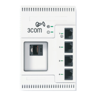
2. NJ95 Description 2. NJ95 Description The following diagram shows the front view of the NJ95 and both the Universal (2a) and Manufacturer Specific (2b) wall plates. (see descriptions below) Figure 1: NJ95 Feature Description... - Page 10 PBX telephone network Indicates network connection status. Indicates NJ95 power status. NJ95 can be powered from a local power supply (available for purchase from 3Com); required if your network does not support Power Over...
-
Page 11: Installing The Nj95 Network Jack
Figure 2: NJ95 Network Jack Main Unit 1 Install the Universal “wall plate” or Manufacturer-specific “wall plate”. 2 Mount the NJ95 Main unit on the Universal or Manufacturer-specific “wall plate”. 3 Set up the power supply (Appendix C). 3. Installing the NJ95 Network Jack... - Page 12 User Guide 1a. Installing the Universal wall plate Figure 3a: Installing the Universal Wall Plate 1 Thread the RJ-45 Connector attached to the wiring closet cable through the opening in the Universal wall plate (Fig. 3a). If necessary connect the coupler cable (Male RJ-45) to the female RJ-45 connector attached to the Network cable and thread it through the Universal wall plate (Fig.
- Page 13 3. Installing the NJ95 Network Jack Figure 3b: Installing the Universal Wall Plate (with Coupler Cable) 2 Mount the Universal wall plate to the Outlet box with the screws provided.
- Page 14 User Guide 1b. Installing the Manufacturer-specific wall plate Figure 4: Installing the Manufacturer-specific Wall Plate 1 Mount the manufacturer-specific connectors (which are connected to the network cabling) on the manufacturer- specific wall plate. 2 Mount the manufacturer-specific wall plate to the Outlet box with the screws provided.
- Page 15 2a. Mount the NJ95 Main unit on the Universal or Manufacturer-specific wall plate. 1 Ethernet Uplink port Connects the NJ95 to the network. 2 Screw Tab Guide 3 Main Latch 4 Alignment Tabs 3. Installing the NJ95 Network Jack Figure 5: Rear view of NJ95...
- Page 16 User Guide 2b. Mounting the NJ95 Main unit to the wall plate Figure 6a: Mounting the NJ95 Main unit to the Universal Wall plate...
- Page 17 Figure 6b: Mounting the NJ95 to the Manufacturer-specific Wall plate 1 Groove for RJ-45 Jack release 2 Screw Tab 3 Slots for Alignment Tabs 3. Installing the NJ95 Network Jack Insert a pin through the groove to release the RJ-...
- Page 18 3 Align the Alignment Tabs on the main unit with the slots (Item #3) in the Wall plate. 4 Snap the Main unit into the Wall plate). 2c. Fastening the NJ95 Figure 7: Securing the NJ95 Main unit to the Wall plate...
- Page 19 1 Screw in the Retaining Screw (Item #1) 2 Secure the Main Latch Fastener (Item #2) NOTE: Make sure the vents along the edges of the NJ95 faceplate are clear of any obstructions. CAUTION: Make sure that you have sufficient clearance on all sides to access release points, retaining screw, and fastener.
- Page 20 On—The NJ95 is receiving power (local or via the network). Off—The NJ95 is not receiving power. (Power) CAUTION: Make sure the port on the wiring closet switch to which the NJ95 is connected is configured as a standard MDI port.
-
Page 21: Un-Installing The Nj95 Network Jack
4. Un-Installing the NJ95 Network Jack 4. Un-Installing the NJ95 Network Jack Figure 8: Unfastening the NJ95 Main unit from the Wall plate 1 Unscrew the Retaining Screw (Item #1) 2 Release the Main Latch Fastener (Item #2). - Page 22 User Guide Figure 9a: Removing the NJ95 from the Universal Wall plate...
- Page 23 4. Un-Installing the NJ95 Network Jack Figure 9b: Removing the NJ95 from the Manufacturer-specific Wall plate 3 Insert a pin (paper clip) along the groove (Item #1) to release the RJ-45 plug. 4 Pull the Main unit away from the Wall plate.
- Page 24 User Guide...
-
Page 25: Appendix A: Detail Description Of Nj95
NJ95 for 10 Mbps or 100 Mbps connections automatically. Power to the NJ95 can be provided in one of the following ways: Power over Ethernet using an Integrated Switch: Over the network via an integrated switch that supports IEEE 802.3af-compatible Power Over Ethernet (also known as In-... - Page 26 After the NJ95 is installed, connect your networking devices (such as computers, printers, etc.) to any of the four switched ports on the front of the NJ95. If you installed the manufacturer- specific wall plate, you can connect to another device to the...
-
Page 27: Appendix B: Wall Plate Dimensions
Appendix B: Wall Plate Dimensions Appendix B: Wall Plate Dimensions Make sure the wall or cubicle opening where the NJ95 is being installed complies with the relevant standard, as described below. British Standard Institute (BSI) – BS 4664:1970 Figure 10: Wall Plate Dimensions - Two hole... - Page 28 User Guide There are instances where you would have a four hole outlet box, where the wall plate can be oriented Horizontally or Vertically. Such an instance is described below: Figure 11: Wall Plate Dimensions - Four hole...
-
Page 29: Appendix C: Setting Up The Power Supply
Appendix C: Setting up the Power Supply Power to the NJ95 can be supplied one of the following ways: Over the network via an integrated switch that supports Power Over Ethernet. Over the network via a multi-port Ethernet power supply. - Page 30 User Guide Using an Integrated Switch with Power Over Ethernet You must have a switch on the network that provides Power over Ethernet, compliant to the IEEE 802.3af standard. Figure 12: Using an Integrated Switch with Power over Ethernet...
- Page 31 To use a multi-port Ethernet power supply, you must connect the power supply to your network, as shown in figure 13. The multi-port Ethernet power supply from 3Com connects to an existing Ethernet or Fast Ethernet infrastructure with standard Category 5 or Category 5e UTP cabling, and powers up to 24 NJ95 Network Jacks.
- Page 32 User Guide Figure 13: Using a Multi-port Ethernet Power Supply...
- Page 33 Using a Single-port Ethernet Power Supply To use a single-port Ethernet power supply, connect the power supply to the network hub or switch and to the NJ95, as shown in figure 14. See “Obtaining Optional Components” in Appendix E for ordering information. For complete installation instructions, see the single-port Ethernet power supply documentation.
- Page 34 If your network does not support Power Over Ethernet, or if you are not using a single-port or multi-port Ethernet power supply, you must purchase a local power supply from 3Com (see “Obtaining Optional Components” in Appendix E). To use the local power supply, make sure you have an electrical outlet near the site where the NJ95 will be installed.
- Page 35 NOTE: Completing these procedures in sequence will reduce issues during the installation process. CAUTION: ONLY use the local power supply available from 3Com. Failure to do so may result in damage to the NJ95 Network Jack, or may result in a hazardous situation.
- Page 36 User Guide...
-
Page 37: Appendix D: Specifications
Appendix D: Specifications Hardware NJ95 Power consumption Network Interface 10 Mbps Ethernet 10BASE-T 100 Mbps Ethernet 100BASE-TX Appendix D: Specifications 5 watts (max) Ethernet IEEE 802.3 industry standard for a 10 Mbps baseband CSMA/CD local area network Ethernet IEEE 802.3u industry standard for... - Page 38 Power Prioritization: 802.1p (QoS) Communication speed (10 Mbps or 100 Mbps) and duplex mode (full or half) is determined through auto-negotiation with the attached devices. The NJ95 attempts to negotiate the fastest connection possible (100 Mbps full- duplex). ˚ ˚...
- Page 39 Features Power Over Ethernet Local power supply Voice Over IP (VoIP) Appendix D: Specifications Compatible with IEEE 802.3af Required for networks that do not support Power Over Ethernet Compatible with VoIP standard.
- Page 40 User Guide...
-
Page 41: Appendix E: Obtaining Optional Components
Appendix E: Obtaining Optional Components The NJ95 works with the following optional components. Updated information is available online at www.3com.com/ products. Component Purpose Wall plates For installing manufacturer specific connectors and mounting the Main Unit. Single-port For providing Power Over Ethernet Ethernet power to power a single NJ95. - Page 42 User Guide...
-
Page 43: Appendix F: Setting Up The Network Cabling At Your Site
2 Terminate the other end of the cable at the location where the NJ95 is being installed using a female RJ-45 connector. Refer to the connector manufacturer’s instructions for terminating the cable. Be sure to test the connector and verify it is working. - Page 44 User Guide...
-
Page 45: Appendix G: Troubleshooting The Nj95
Adheres to proper length and cabling specifications for your network. Make sure the port on the switch to which the NJ95 is connected is configured as a standard MDI-X port. Make sure all cables connecting the NJ95 to the patch panel are straight-through cables (not crossover cables). - Page 46 User Guide Verify that the DIP Switch settings are all set to OFF:...
-
Page 47: Appendix H: Contacting Technical Support
Hours of operation are subject to change. See “Support from 3Com” on page 43. Online Technical Services 3Com offers worldwide product support 24 hours a day, 7 days a week, through the following online systems: World Wide Web site 3Com Knowledgebase Web Services... - Page 48 3Com FTP Site across the Internet from the 3Com public FTP site. This service is available 24 hours a day, 7 days a week. To connect to the 3Com FTP site, enter the following information into your FTP client: Host name: ftp.3com.com User name: anonymous Password: <your Internet e-mail address>...
- Page 49 If you are unable to consult your network supplier, see the following section on how to contact 3Com. Support from 3Com If you are unable to obtain assistance from the 3Com online technical resources or from your network supplier, 3Com offers technical telephone support services. To find out more about your support options, call the 3Com technical telephone support phone number: UK- 0870 909 3266;...
- Page 50 User Guide When you contact 3Com for assistance, have the following information ready: Product model name, part number, and serial number A list of system hardware and software, including revision levels Diagnostic error messages Details about recent configuration changes, if applicable...
- Page 51 Switzerland All Other Countries Returning Products for Repair directly to 3Com for repair, you must first obtain an authorization number. Products sent to 3Com without authorization numbers will be returned to the sender unopened, at the sender’s expense. To obtain an authorization number, call: UK- 0870 909 3266;...
- Page 52 User Guide...
-
Page 53: Com Corporation Limited Warranty
FOR NON-US CUSTOMERS: Where a limited lifetime warranty is not permitted by local law, a 10 year warranty period shall be given by 3Com. The duration of this warranty shall be modified where necessary to meet any minimum warranty period required by law. - Page 54 Responsibility for loss or damage does not transfer to 3Com until the returned item is received by 3Com. 3Com will retain risk of loss or damage until the item is delivered to Customer. For non-US Customers, the word 'prepaid' shall be omitted where this requirement is not permitted by law.
- Page 55 LIGHTNING, POWER CUTS OR OUTAGES, OTHER HAZARDS, OR ACTS OF GOD. IMITATION OF IABILITY TO THE FULL EXTENT ALLOWED BY LAW, 3COM ALSO EXCLUDES FOR ITSELF AND ITS LICENSORS AND SUPPLIERS ANY LIABILITY, WHETHER BASED IN CONTRACT OR TORT (INCLUDING NEGLIGENCE), FOR INCIDENTAL, CONSEQUENTIAL, INDIRECT,...
- Page 56 The United Nations Convention on Contracts for the International Sale of Goods is hereby excluded in its entirety from application to this Limited Warranty. 3Com Corporation 5400 Bayfront Plaza P.O. Box 58145 Santa Clara, CA 95052-8145 (408) 326-5000 Rev.
-
Page 57: Fcc Declaration Of Conformity
Changes or modifications not expressly approved by 3Com could void the user’s authority to operate this equipment. -
Page 58: European Union Declaration Of Conformity
European Union Declaration of Conformity This product is in compliance with the essential requirements and other relevant provisions of Directives 73/23/EEC and 89/336/EEC. 3Com Corporation, 5400 Bayfront Plaza, P.O. Box 58145, Santa Clara, CA 95052-8145 09-2264-000... - Page 60 3Com Corporation P.O. Box 58145 5400 Bayfront Plaza Santa Clara, CA 95052-8145 U.S.A. www.3com.com 09-2264-000 Printed in the U.S.A.
Need help?
Do you have a question about the NJ95 Network Jack and is the answer not in the manual?
Questions and answers