
Subscribe to Our Youtube Channel
Related Manuals for 3Com 3CNJ100


Summary of Contents for 3Com 3CNJ100
-
Page 1: Installation Guide
Installation Guide NJ100 Network Jack 3CNJ100 4-port 10/100 Mbps Unmanaged Ethernet Switch http://www.3com.com/ http://www.3com.com/productreg 09-2141-000 Published September 2001... - Page 2 3Com Corporation. 3Com Corporation reserves the right to revise this documentation and to make changes in content from time to time without obligation on the part of 3Com Corporation to provide notification of such revision or change.
-
Page 3: Table Of Contents
Using an Integrated Switch with Power Over Ethernet Using a Multi-port Ethernet Power Supply Using a Single-port Ethernet Power Supply Using the 3Com Local Power Supply Setting the Power Over Ethernet Dip Switches Installing the Adapter Plate and Pass-Through Ports Planning the Installation... - Page 4 Contents Contacting Technical Support One-Year Free Installation Support Online Technical Services World Wide Web Site 3Com Knowledgebase Web Services 3Com FTP Site Support from Your Network Supplier Support from 3Com Returning Products for Repair 3Com Corporation Limited Warranty FCC Class A Verification Statement...
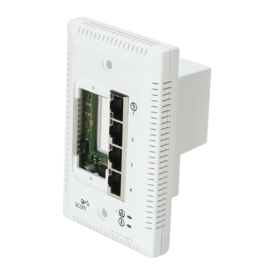
- Page 5 Installation Guide The 3Com Network Jack is a 4-port, unmanaged Ethernet switch that fits into any standard electrical wall outlet or data port opening. The Network Jack brings switching capabilities to any single port on an Ethernet network by allowing up to four networking...
-
Page 6: About The Network Jack
Installation Guide About the Network Jack The following diagram shows the front view of the Network Jack. - Page 7 PBX telephone. The adapter plates are available from 3Com. However, you must purchase the connectors from the manufacturer. See “Installing the Adapter Plate and Pass-Through Ports” on page 15 for more information.
- Page 8 Installation Guide The following diagram shows the back view of the Network Jack. o rk In te rf a D IN U .S .A . s te d to w it S ta a rd...
- Page 9 1 Ethernet uplink Connects the Network Jack to the network. port Make sure the port on the network switch to which the Network Jack is connected is configured as a standard MDI-X port. 2 Slot for adapter Can be fitted with an adapter plate, which can plate be installed with up to two pass-through ports.
-
Page 10: Before You Begin
Panduit (RJ-45 and RJ-11) Avaya (RJ-45 and RJ-11) NOTE: The connectors for the adapter plates must be purchased from the manufacturer. For a list of supported connectors, go to www.3com.com/. Adapter plate screws (2) for mounting the adapter plate to the Network Jack. -
Page 11: Obtaining Optional Components
Obtaining Optional Components Obtaining Optional Components The Network Jack works with the following optional components, all of which are available from 3Com. Order online at www.3com.com or by calling 1-877-949-3266. Component Purpose Adapter plates For installing pass-through port connectors of your choice that allow... -
Page 12: Installing The Network Jack
5 Set up the network cabling at your site (page 19). 6 Connect the Network Jack to the network (page 19). 7 Mount the Network Jack to the wall or office cubicle (page 22). 3C Number(s) Check the 3Com web site 3CNJTESTER... - Page 13 8 Connect the local power supply (page 23; optional) not required if your network supports Power Over Ethernet or if you are using a single-port or multi-port power supply). 9 Connect network devices to the Network Jack (page 23). The following diagram displays an overview of the recommended installation, where the Network Jack is being connected to an Ethernet network cable that is terminated with a female RJ-45 connector.
-
Page 14: Setting Up The Power Supply
Over the network via a multi-port Ethernet power supply. Over the network via a single-port Ethernet power supply. Locally via a 3Com local power supply. Before you begin the installation, determine which type of power supply the Network Jack will use. - Page 15 The multi-port Ethernet power supply from 3Com connects to an existing Ethernet or Fast Ethernet infrastructure with standard Category 5 or Category 5e UTP cabling, and powers up to 24 Network Jacks. See “Obtaining Optional Components” on page 7 for ordering information. For complete installation instructions, see the multi-port Ethernet power supply documentation.
-
Page 16: Using A Single-Port Ethernet Power Supply
Using a Single-port Ethernet Power Supply To use a single-port power supply, connect the power supply to the network hub or switch and to the Network Jack, as shown in the following illustration. See “Obtaining Optional Components” on page 7 for ordering information. For complete installation instructions, see the single-port Ethernet power supply documentation. -
Page 17: Setting The Power Over Ethernet Dip Switches
Do not change dip switches 1 and 2 from their factory default settings (OFF). Changing these settings may result in performance degradation. 1 On the back of the Network Jack, remove the dip switch cover. Dip switch cover N et... - Page 18 Power Over Ethernet Supported Numbers Capacitive Power Discovery/24V Ethernet Power Source Capacitive Power Discovery/48V Ethernet Power Source IEEE 802.3af-compatible Power Over Ethernet 3 Replace the dip switch cover. Setting 4 (ON) 3 (ON) 4 (ON) 3 (OFF) 4 (OFF) 3 (OFF)
-
Page 19: Installing The Adapter Plate And Pass-Through Ports
20-pack). For a list of connectors that are supported with the Network Jack adapter plates, go to www.3com.com. NOTE: If you are not planning on installing the adapter plate and pass-through ports, skip this section. Go to “Planning the Installation”... - Page 20 Installation Guide 2 Thread the network cable(s) through the empty slot on the Network Jack. Wall To wiring closet 3 Terminate the end of the network cable(s) with the connector(s) you purchased separately. Refer to the connector manufacturer’s instructions for terminating the cable.
-
Page 21: Planning The Installation
Planning the Installation When installed, the back of the Network Jack extends into a wall or cubicle opening 1.5 inches. Because the depth of some wall and cubicle openings differ, observe the following requirements and recommendations before installing the Network Jack: Make sure the wall or cubicle opening where the Network Jack is being installed complies with the NEMA-WD6 standard, as described below. - Page 22 Installation Guide Make sure the distance between the back of the Network Jack and the inside of the wall or cubicle opening is at least 1.5 inches (3 inches is recommended). NOTE: Some cubicle openings have a depth of 1.2 inches.
-
Page 23: Setting Up The Network Cabling At Your Site
(as described in the previous section, “Setting up the Network Cabling at Your Site”). CAUTION: Make sure the port on the network switch to which the Network Jack is connected is configured as a standard MDI-X port. - Page 24 Installation Guide If the end of the cable is terminated with a female RJ-45 connector, use the RJ-45 coupler cable included in the package to connect the Network Jack to the network cable (recommended installation.) Wall RJ-45 coupler cable To wiring closet Network cable...
- Page 25 Installing the Network Jack If the end of the cable is terminated with a male connector, connect the network cable directly into the Ethernet uplink port. Wall Network cable To wiring closet...
-
Page 26: Mounting The Network Jack
Installation Guide Mounting the Network Jack After connecting the Network Jack to the network, use the two provided screws to mount the Network Jack in any standard NEMA-WD6 cubicle opening or wall outlet. If the cubicle or wall opening has a depth of fewer than five inches, does not support the NEMA-WD6 standard, or does not have pre-drilled screw holes, mount the Network Jack using the extension ring, as shown below. -
Page 27: Connecting The Local Power Supply (Optional)
Network Jack, and then plug it into any standard electrical outlet. CAUTION: Use the local power supply available from 3Com. Failure to do so may result in damage to the Network Jack, or may result in a hazardous situation. Connecting Devices to the Network Jack After the Network Jack is installed and mounted, connect your networking devices (such as computers, printers, etc.) to any of... -
Page 28: Checking The Leds
Installation Guide Checking the LEDs You can verify the Network Jack installation by checking the LEDs. Description On—The Network Jack is connected to the network and a link has been established. Off—There is no connection to the network. (LAN) On—The Network Jack is receiving power (local or via the network). - Page 29 Be sure to test the connector and verify it is working. Has a valid connection to the network. Adheres to proper length and cabling specifications for your network. Make sure the port on the switch to which the Network Jack is connected is configured as a standard MDI-X port.
-
Page 30: Specifications
Installation Guide Specifications 4.50" 2.75" Hardware Power consumption 5 watts without power forwarding Maximum 13 watts with power forwarding (depending on the device drawing power) Network Interface 10 Mbps Ethernet Ethernet IEEE 802.3 industry standard for 10BASE-T a 10 Mbps baseband CSMA/CD local area network 100 Mbps Ethernet Ethernet IEEE 802.3u industry standard for... - Page 31 Performance Auto-negotiation Communication speed (10 Mbps or 100 Mbps) and duplex mode (full or half) is determined through auto-negotiation with the attached devices. The Network Jack attempts to negotiate the fastest connection possible (100 Mbps full-duplex). Environment ˚ ˚ ˚ Operating temperature 32 to 104 F (0...
-
Page 32: Contacting Technical Support
This appendix describes these services. Information contained in this appendix is correct at time of publication. For the most recent information, 3Com recommends that you access the 3Com Corporation World Wide Web site. One-Year Free Installation Support 3Com provides free installation and troubleshooting telephone support for this product for one (1) year from the date of purchase. -
Page 33: Online Technical Services
Contacting Technical Support Online Technical Services 3Com offers worldwide product support 24 hours a day, 7 days a week, through the following online systems: World Wide Web site 3Com Knowledgebase Web Services 3Com FTP site World Wide Web Site To access the latest networking information on the 3Com Corporation World Wide Web site, enter this URL into your Internet browser: http://www.3com.com/... -
Page 34: 3Com Ftp Site
3Com FTP Site Download drivers, patches, software, and MIBs across the Internet from the 3Com public FTP site. This service is available 24 hours a day, 7 days a week. To connect to the 3Com FTP site, enter the following information into your FTP client: Host name: ftp.3com.com... -
Page 35: Support From 3Com
Details about recent configuration changes, if applicable Returning Products for Repair Before you send a product directly to 3Com for repair, you must first obtain an authorization number. Products sent to 3Com without authorization numbers will be returned to the sender unopened, at the sender’s expense. -
Page 37: Limited Warranty And Regulatory Compliance Information
FOR NON-US CUSTOMERS: Where a limited lifetime warranty is not permitted by local law, a 10 year warranty period shall be given by 3Com. The duration of this warranty shall be modified where necessary to meet any minimum warranty period required by law. - Page 38 Responsibility for loss or damage does not transfer to 3Com until the returned item is received by 3Com. 3Com will retain risk of loss or damage until the item is delivered to Customer. For non-US Customers, the word 'prepaid' shall be omitted where this requirement is not permitted by law.
- Page 39 LIGHTNING, POWER CUTS OR OUTAGES, OTHER HAZARDS, OR ACTS OF GOD. IMITATION OF IABILITY TO THE FULL EXTENT ALLOWED BY LAW, 3COM ALSO EXCLUDES FOR ITSELF AND ITS LICENSORS AND SUPPLIERS ANY LIABILITY, WHETHER BASED IN CONTRACT OR TORT (INCLUDING NEGLIGENCE), FOR INCIDENTAL, CONSEQUENTIAL, INDIRECT,...
- Page 40 U.S.A., and by the laws of the United States, excluding their conflicts of laws principles. The United Nations Convention on Contracts for the International Sale of Goods is hereby excluded in its entirety from application to this Limited Warranty. 3Com Corporation 5400 Bayfront Plaza P.O. Box 58145...
-
Page 41: Fcc Class A Verification Statement
Operation of this equipment in a residential area is likely to cause harmful interference, in which case, the user will be required to correct the interference at the user’s own expense. Changes or modifications not expressly approved by 3Com could void the user’s authority to operate this equipment. FCC Declaration of Conformity...
Need help?
Do you have a question about the 3CNJ100 and is the answer not in the manual?
Questions and answers