
Subscribe to Our Youtube Channel
Related Manuals for ATEN VE8900


Summary of Contents for ATEN VE8900
- Page 1 HDMI over IP Video Extender VE8900 / VE8950 4K HDMI over IP Video Extender with PoE VE8952 User Manual www.aten.com...
-
Page 2: Emc Information
VE8900 / VE8950 / VE8952 User Manual EMC Information FEDERAL COMMUNICATIONS COMMISSION INTERFERENCE STATEMENT: This equipment has been tested and found to comply with the limits for a Class A digital device, pursuant to Part 15 of the FCC Rules. These limits are designed to provide reasonable protection against harmful interference when the equipment is operated in a commercial environment. -
Page 3: About This Manual
VE8900 / VE8950 / VE8952 User Manual About This Manual This User Manual is provided to help you get the most from your VE8900 / VE8950 / VE8952 device and the ATEN VE Manager. It covers all aspects of installation, configuration, and operation. An overview of the information found in the manual is provided below. -
Page 4: Conventions
For information about all ATEN products and how they can help you connect without limits, visit ATEN on the Web or contact an ATEN Authorized Reseller. Visit ATEN on the Web for a list of locations and telephone numbers: International http://www.aten.com... -
Page 5: User Information
VE8900 / VE8950 / VE8952 User Manual User Information Online Registration Be sure to register your product at our online support center: International http://eservice.aten.com Telephone Support For telephone support, call this number: International 886-2-8692-6959 China 86-400-810-0-810 Japan 81-3-5615-5811 Korea 82-2-467-6789... -
Page 6: Package Contents
VE8900 / VE8950 / VE8952 User Manual Package Contents Check to make sure that all of the components are present and in good order. If anything is missing or was damaged in shipping, contact your dealer. VE8900T 1 VE8900 HDMI over IP Transmitter... - Page 7 Note: The VE8900 / VE8950 / VE8952 product firmware may have been updated with new features after the release of this manual. For an up-to-...
-
Page 8: Table Of Contents
Rack Mount ..........14 Connecting VE8900 / VE8950 ....... . . 15 Connecting VE8952 . - Page 9 Setup Profile Schedules ........49 Managing VE8900 / VE8950 / VE8952 Devices ....52 Checking VE8900 / VE8950 / VE8952 Statuses .
- Page 10 Configuring the EDID Mode ....... . 78 Rebooting the VE8900 / VE8950 / VE8952 ....79 Examples.
-
Page 11: Introduction And Getting Started
(VE8900) /4K (VE8950 / VE8952) signal transmission, and designed to be easy to set up and operate, the VE8900 / VE8950 / VE8952 Video over IP Extender is an ideal product for a wide range of environments, such as trade shows, airports, university campuses, conference centers, and shopping centers. -
Page 12: Features And Benefits
Power over Ethernet Support Locate VE8952 anywhere without having to install additional power cabling and outlets Note: Only VE8952 supports PoE function, and VE8900 / VE8950 does not. Limitless Scalability and Flexibility Extends AV connections from a simple point-to-point to a multi-point to multi-point setup via LAN without distance limitations ... - Page 13 Collaboration with ATEN Control System Integrated solution – Compatible with ATEN Control System, allowing users to directly operate VE8900 / VE8950 / VE8952 via CLI Telnet, RS- 232 protocol, or Mobile Control App Effortless operation – One click to effectively operate VE Manager, TV,...
- Page 14 VE8900 / VE8950 / VE8952 User Manual Spontaneous Scheduling Management Offers an user-friendly scheduling management function for users to pre- plan the display schedule Provides robust and intuitive scheduling management options to help users to manage all events in the calendar to as detailed as to setting events to minute intervals ...
- Page 15 Note: Depending on your network architecture, we recommend daisy chaining up to 30 units. Please contact ATEN representatives for more details. For Daisy Chain installation setup for VE8952 units, only the first level of VE8952 supports PoE powering function. All the other VE8952 units installed on the second level or above will need power adapter and PoE does not work.
- Page 16 RS-232 Channel – bi-directional RS-232 serial port allows for connection of peripherals such as touch screens and bar code scanners Note: Each VE8900 / VE8950 / VE8952 transmitter can be controlled by a total of 4 USB touch screens installed to VE8900 / VE8950 / VE8952 receivers.
-
Page 17: Getting Started Tasks
1. Decide your network architecture and configuration. For more information, see the ATEN HDMI over IP Video Extender System Implementation Guide. 2. Mount your VE8900 / VE8950 / VE8952 devices on walls or racks. For more information, see Mounting the VE8900 / VE8950 / VE8952 Device, page 14. - Page 18 VE8900 / VE8950 / VE8952 User Manual This Page Intentionally Left Blank...
-
Page 19: Hardware Setup
Before you proceed to hardware setup: 1. Please review the safety information regarding the placement of this device in Safety Instructions, page 95. 2. Do not power on the VE8900 / VE8950 / VE8952 device until all the necessary hardware is connected. Components... -
Page 20: Ve8900T / Ve8950T / Ve8952T Rear View
Component Function LAN Port with Connects the unit to LAN with a network cable. Note: Only VE8952 supports PoE function, and VE8900 / VE8950 does not. Power Jack Connects to the DC power adapter to provide power to the unit. - Page 21 Function LAN 1 Port Connects the unit to LAN with a network cable. with PoE Note: Only VE8952 supports PoE function, and VE8900 / VE8950 does not. LAN 2 Port Connects to another VE8900R / VE8950R with a network cable in a daisy-chain setup.
-
Page 22: Ve8900T / Ve8950T / Ve8952T Top View
ID Display An ID display that identifies its ID number. Panel Prev (+) / Next Assign ID numbers on VE8900 / VE8950 devices. (-) Buttons Assign the source video (transmitter) for the receiver. Link LED Lights orange to indicate the LAN Port 1 is connected to an Ethernet switch. -
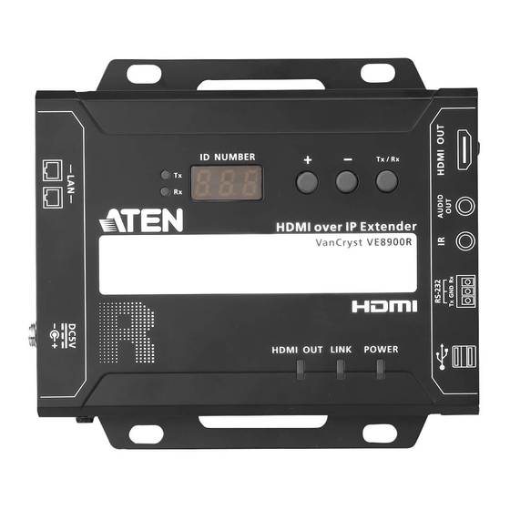
Page 23: Ve8900R / Ve8950R / Ve8952R Top View
An ID display that identifies its ID number or the transmitter’s ID Panel number when the panel control is switched to Tx. Prev (+) / Next Assign ID numbers on VE8900 / VE8950 devices. (-) Buttons Assign the source video (transmitter) for the receiver. Tx/Rx Switch... -
Page 24: Mounting The Ve8900 / Ve8950 / Ve8952 Device
VE8900 / VE8950 / VE8952 User Manual Mounting the VE8900 / VE8950 / VE8952 Device Wall Mount Secure or hang the VE8900 / VE8950 / VE8952 device to the wall using the built-in brackets. Rack Mount Use the VE-RMK1U Rack Mount Kit to rack-mount the VE8900 / VE8950 / VE8952. -
Page 25: Connecting Ve8900 / Ve8950
Chapter 2. Hardware Setup Connecting VE8900 / VE8950 Follow the steps below to connect your VE8900 / VE8950 devices with the hardware as required. Note: For details on LED indicators to help you identify statuses of connection or signal transmission, see Status LEDs, page 21. - Page 26 VE8900 / VE8950 / VE8952 User Manual 1. Connect the HDMI In port on the VE8900T / VE8950T device to the HDMI Out port on your video source device using an HDMI cable. 2. Connect the HDMI Out port on the VE8900R / VE8950R device to the HDMI In port on your display device using an HDMI cable.
- Page 27 System Settings > Receiver > IR/RS232 or USB in VE Manager and select the signal source. 2. Each VE8900 / VE8950 transmitter can be controlled by a total of 4 USB touch screens installed to VE8900 / VE8950 receivers.
-
Page 28: Connecting Ve8952
Note: For details on LED indicators to help you identify statuses of connection or signal transmission, see Status LEDs, page 21. For a list of compatible ATEN products, visit the VE8952 product web page at www.aten.com Audio Speaker... - Page 29 Chapter 2. Hardware Setup 1. Connect a video source device to the HDMI Input Port on the VE8952T using an HDMI cable. 2. Connect a video display device to the HDMI Output Port on the VE8952R using an HDMI cable. 3.
- Page 30 VE8900 / VE8950 / VE8952 User Manual Note: 1. The IR, RS-232, and USB signal transmissions are disabled by default. To enable the functions, go to System Settings > Receiver > IR/RS232 or USB in VE Manager and select the signal source.
-
Page 31: Panel Operation
RJ-45 Connector Lights green LAN is connected and no data is being transmitted. (Right LED) Blinks green LAN is connected and data is being transmitted. Note: The HDMI Out LED is only available on VE8900 / VE8950 / VE8952 receivers. -
Page 32: Panel Controls
VE8952 User Manual Panel Controls VE8900 / VE8950 VE8900/VE8950 Receiver VE8900/VE8950 Transmitter Note: The unit used in the diagram above is VE8900 / VE8950, the panel control for VE8952 is identical. Name Description Tx/Rx LEDs Lights to indicate whether the displayed ID number is of... - Page 33 The VE8900 / VE8950 / VE8952 device automatically locks its panel when it idles for 1 minute. To unlock the panel, press and hold the Down (- ) button for 3 seconds. Tx/Rx LEDs and Tx/Rx Switch Button are only available on VE8900 / VE8950 / VE8952 receivers.
-
Page 34: Assigning Sources Using The Device Panel
VE8900 / VE8950 VE8952 User Manual Assigning Sources Using the Device Panel 1. Assign an ID number to each of your VE8900R / VE8950R / VE8952 devices. a) On a VE8900R / VE8950R / VE8952R device, make sure the control is switched to Rx, in which case the Rx LED lights up. -
Page 35: Management
Chapter 4 Management Overview ATEN VE8900 / VE8950 / VE8952 HDMI over IP Video Extenders can be remotely and centrally managed using a built-in utility program, the ATEN VE Manager. Accessed through a web browser, this utility provides a central... -
Page 36: Looking Up The Login Ip Address
6. Click Enumerate to search for ATEN devices in the network. The detected devices are shown in Device List. 7. Use the IP address of any VE8900 / VE8950 / VE8952 transmitter to log in VE Manager. Looking Up the Login IP Address from OSD Alternatively, you can obtain the IP address from the HDMI monitor connected to the VE8900 / VE8950 / VE8952 receiver. -
Page 37: Find My Ve Extension
1. For the extension application, go to the download link: https://www.aten.com/global/en/supportcenter/downloads/ 2. Type in VE8900 / VE8950 / VE8952 in the field below “Download materials for other products” and press OK. 3. Scroll down the page and click either VE8900T, VE8900R, or VE8952R. - Page 38 VE8900 / VE8950 / VE8952 User Manual Clicking the extension application will bring up a window as shown below: The window will display all the units within the network as a list. Click the icon (top right-hand corner) to refresh the list.
-
Page 39: Start Ve Manager Using Find My Ve Extension
Chapter 4. Management Start VE Manager using Find My VE Extension You can go directly into VE Manager login page using the Find My VE Extension. To do so, follow the steps below: 1. In the Windows Start menu, click to select Find My VE. 2. - Page 40 VE8900 / VE8950 / VE8952 User Manual Please refer to Logging In and Configuring VE Manager on page 31 for information about logging in.
-
Page 41: Logging In And Configuring Ve Manager
Chapter 4. Management Logging In and Configuring VE Manager On a computer with web access, follow the steps below to log in VE Manager. 1. Open a web browser and type the IP address you obtained using IP Installer Utility. This screen appears. 2. - Page 42 To specify a different date and time, type the desired date and time. Make sure the date is typed in this format: YYYY/MM/DD. 4. Click NEXT. This screen appears. The setup wizard lists the VE8900 / VE8950 / VE8952 transmitters and receivers found in the network.
- Page 43 When the assignment is complete, VE Manager displays the assigned IP addresses. 8. To re-assign device IDs, click and type a new ID for the target VE8900 / VE8950 / VE8952 device. 9. Click Done. The VE Manager’s main screen appears.
-
Page 44: The Main Screen
VE8900 / VE8950 / VE8952 User Manual The Main Screen You can access the following controls from the VE Manager’s main screen. No. Component Description Previews for Video Shows a preview of created video walls, Walls and Receivers individual video receivers, and daisy chain setups. -
Page 45: Apply / Auto Apply
No. Component Description Globally enables or disables panel control of the VE8900 / VE8950 / VE8952 devices used in managed video walls. To enable or disable panel control of VE8900 / VE8950 / VE8952 devices for a single video wall, use the OSD setting for a preview window. -
Page 46: Assigning Sources Using Ve Manager
VE8900 / VE8950 / VE8952 User Manual Assigning Sources Using VE Manager Follow the steps below to assign input sources using VE Manager. 1. On the main screen, identify the source you wish to be assigned in the “Source List” and the preview video walls / receivers. - Page 47 , and then click the Receiver tab. The managed VE8900 / VE8950 / VE8952 receivers appear. 2. Assign a source for each of the VE8900 / VE8950 / VE8952 receivers. a) Move the cursor to a receiver. A green arrow appears at the top right corner of the receiver preview window.
- Page 48 Repeat steps 2 (a) to 2 (d) to assign sources for each of the receivers. f) To reboot the VE8900 / VE8950 / VE8952, click the green arrow mentioned in step b), and click Reboot. This warning window appears.
-
Page 49: Configuring And Setting Up A Video Wall
Chapter 4. Management Configuring and Setting Up a Video Wall To configure a video wall, follow the steps below. 1. Make sure you have created a video wall template for your specific needs. For detailed steps, see Creating a Video Wall Layout, page 40. 2. -
Page 50: Creating A Video Wall Layout
VE8900 / VE8950 / VE8952 User Manual Creating a Video Wall Layout 1. To create a new layout, click Create/Edit Video Wall from the main screen. This window appears. A preview of the layout is shown in the middle. 2. Configure your video wall layout as required. Use the preview to help you visualize the layout. - Page 51 Chapter 4. Management Control Description Operation Mode Select an operation mode for your video wall. Video Wall: Select this option to set up a video wall. Splitter: Select this option to set up a display of identical content on multiple monitors. ...
-
Page 52: Editing A Video Wall Layout
VE8900 / VE8950 / VE8952 User Manual 4. Click CREATE. The new video wall template is created. Editing a Video Wall Layout To edit a video wall layout, from the VE Manager’s main screen, click the top- right corner of the layout you wish to edit, and then select Edit. For more... -
Page 53: Editing A Preview
Mute: Disables audio transmission to this video wall. OSD: Enables or disables the panel control of all VE8900 / VE8950 / VE8952 devices for this video wall. Edit: Click to access the video wall layout settings. For more details on video wall settings, see Creating a Video Wall Layout, page 40. -
Page 54: Profile
VE8900 / VE8950 / VE8952 User Manual Profile After configuring video receiver / video wall settings, if you find that you would like to keep the current settings, you can save it as a profile. You can create different profiles and apply them manually, or you can set up profile schedules for switching video display at different times of a day, week or month. - Page 55 Chapter 4. Management 2. Click +Add Profiles for the page below: Profile Name: Enter a profile name. Receivers / Video Walls: Select the receivers / video walls you wish to be in this profile by checking the orange box. Alternatively, you can select all receivers / video walls by checking the Select All option.
-
Page 56: Edit, Delete And Disconnect Profile
VE8900 / VE8950 / VE8952 User Manual Edit, Delete and Disconnect Profile On the profile list, you can edit, delete and disconnect profiles. Click to select the profile you wish to configure and a green arrow will appear. Click the green arrow for a drop-down menu of edit, delete and disconnect options. -
Page 57: Delete
Chapter 4. Management Delete To delete a profile, click the Delete option: The system will ask if you would like to delete this profile. Click OK to proceed or click CANCEL to cancel. Disconnect To disconnect the current profile from the video wall, click Disconnect. The video wall should go blank. -
Page 58: Select / Apply Profile
VE8900 / VE8950 / VE8952 User Manual Select / Apply Profile After creating the profile, you can apply the settings of the profile to the video displays. Follow the steps below to apply the settings: 1. Bring up the profile list. -
Page 59: Setup Profile Schedules
Chapter 4. Management Setup Profile Schedules Follow the steps below to setup profile schedules. 1. On the main screen, click the profile schedule icon on the top right hand corner An example of profile schedule screen (with nothing planned) is shown below: On this page, you can select to show current schedule of either “1 DAY”, “3 next days”, “work week”... - Page 60 VE8900 / VE8950 / VE8952 User Manual 3. Edit / Add the schedule as required: Status: Enable or disable the schedule. Profile: Select a profile. Start Date: Select or enter a start date. End Date: Select or enter an end date.
- Page 61 Chapter 4. Management...
-
Page 62: Managing Ve8900 / Ve8950 / Ve8952 Devices
Transmitter or Receiver tab. The status for a VE8900 / VE8950 / VE8952 device is indicated with a colored circle. See the table below for status indicators and the corresponding descriptions. -
Page 63: System Settings
Video Quality: Click to select a video quality for display. Panel Lock: Select Permanent to lock the panel control of all connected VE8900 / VE8950 / VE8952 devices. To unlock the panel of a single VE8900 /... - Page 64 Installation Wizard: Click on the top-right corner to open up the installation wizard. For details, see Logging In and Configuring VE Manager, page 31. Click Apply for the settings to take effect on the connected VE8900 / VE8950 / VE8952 devices.
-
Page 65: Transmitter Settings
Chapter 5. System Settings Transmitter Settings The Transmitter tab displays the managed VE8900 / VE8950 / VE8952 transmitter devices and provides access to the settings. To access transmitter settings, follow the steps below. 1. From the main screen, click , and then click the Transmitter tab. The managed VE8900 / VE8950 / VE8952 transmitters appear. - Page 66 VE8900 / VE8950 / VE8952 User Manual 5. Configure the settings as required. Name: Click to rename the transmitter. IP Address: Specifies how the transmitter obtains its IP address. By default, this field is set to System Auto.
-
Page 67: Receiver Settings
Chapter 5. System Settings Receiver Settings The Receiver tab displays managed VE8900 / VE8950 / VE8952 receiver devices and provides access to the settings. To access receiver settings, follow the steps below. 1. From the main screen, click , and then click the Receiver tab. The managed VE8900 / VE8950 / VE8952 receivers appear. - Page 68 USB signals. Fast Switching: Click to define the resolution for fast switching. Note: For best results, ATEN recommends setting this field to the same resolution with your video source and make sure this setting is identical on all VE8900 / VE8950 / VE8952 receivers.
-
Page 69: Batch Configuration
Chapter 5. System Settings Batch Configuration A batch configuration option is available for both Transmitters and Receivers, and appears on the top right-hand corner of the page as Quick Configuration. If you wish to adjust a particular setting for a group of devices, do the following: 1. - Page 70 VE8900 / VE8950 / VE8952 User Manual 3. Check the devices you wish to configure or, if you wish to select all the devices on the list, check “Select All” (on the top left-hand corner) and click NEXT. The Quick Configure window will appear and you can see each device’s current status.
-
Page 71: Maintenance
Upgrading VE8900 / VE8950 / VE8952 Device Firmware To upgrade the VE8900 / VE8950 / VE8952 device firmware, follow the steps below. 1. From the main screen, click , and click the Maintenance tab. -
Page 72: Synchronizing All Devices
When you wish to add or replace devices, click the Sync All button for the system to recognize the added / replaced device. Backing Up VE8900 / VE8950 / VE8952 Device Settings You can export transmitter and receiver layouts for backup or migration purposes. -
Page 73: Restoring Ve8900 / Ve8950 / Ve8952 Device Settings
When the I/O firmware upgrade fails. The unit is not powered on with unknown reason To set the VE8900 / VE8950 / VE8952 to recovery mode, do the following: 1. Press and hold the Prev (+) pushbutton. 2. Power on the VE8900 / VE8950 / VE8952. -
Page 74: Account Settings
VE8900 / VE8950 / VE8952 User Manual Account Settings VE Manager contains two account levels, the Administrator and the User level. The default passwords and privileges are detailed in the table below. Account Level Default Password Privileges Administrator password All settings... -
Page 75: Cli Commands
You can manage and configure the VE8900 / VE8950 / VE8952 devices using telnet, TCP, or RS-232 commands from a PC or an ATEN Control Box. Before You Start Make sure you have installed a PC or an ATEN Control Box to the Ethernet switch in your setup, as illustrated below:... -
Page 76: Executing Commands
2. Depending on the supported command type for your PC, do the following to connect to your deployment. Telnet connections In the command prompt, type the IP address of any VE8900 / VE8950 / VE8952 receiver in your setup and use port 23. For example: TCP connections In the command prompt, type the IP address of any VE8900 / VE8950 / VE8952 receiver in your setup and use port 9138. - Page 77 Chapter 6. CLI Commands 3. Type the command you wish to execute. For information on command syntax, see Commands, page 68. 4. Press [Enter] to execute the command. 5. When the command is successfully executed, the system returns a confirmation message. 6.
-
Page 78: Commands
VE8900 / VE8950 / VE8952 User Manual Commands Guidelines The general form of a command is: command name + parameter1 + parameter 2 + control 1 + control 2 Always specify the command name first, followed by one or more parameters, and then the controls, if any. -
Page 79: Switching Sources
\r\n Ends the command. Examples To switch the source to a VE8900 transmitter with the IP address of 10.0.90.11 to the VE8900 receiver you used to make the CLI connection, type sw i10.0.90.11 on To switch the source to a VE8950 transmitter with the ID of 1 on a VE8950 receiver with the ID of 5, type sw i1 o5 on ... -
Page 80: Switching Video, Usb, Rs-232, And/Or Ir Paths
Ends the command. Examples To switch the video path of a VE8900 transmitter with the ID of 3 to a VE8900 receiver with an ID of 4, type sw i3 video o4 To switch the usb path of a VE8950 transmitter with the ID of 1 to a... -
Page 81: Disabling Video, Usb, Rs-232, And/Or Ir Paths
Stands for RS-232 path of the specified receiver. Stands for IR path of the specified receiver. \r\n Ends the command. Example To disable the video, USB, RS-232, and IR paths for a VE8900 receiver with an ID of 4, type sw o4 all off... -
Page 82: Displaying Port-Switching Alerts
Use this command to display an alert message in the command line interface whenever a port is switched via the VE Manager, the VE8900 / VE8950 / VE8952 device pushbuttons, or the IR remote control. To enable or disable this... -
Page 83: Looking Up System Settings
+ rx | tx | device | videowall + \r\n Control Description Lists the system information of all VE8900 / VE8950 / VE8952 receivers in the environment, including the device IDs, MAC addresses, IP addresses, firmware versions, and device names. -
Page 84: Configuring Video Wall Settings
<video_wall_ID> Indicates the ID of the video wall on which you wish to display the specified layout and sources. You can also substitute this ID with the ID of any VE8900 / VE8950 / VE8952 receiver used in the target video wall. To look up video wall IDs, use the list command. For details, see Looking Up System Settings, page 73. -
Page 85: Muting Ve8900 / Ve8950 / Ve8952 Receivers Or Video Walls
Indicates the device ID, MAC address, or the IP address of the output (VE8900 / VE8950 / VE8952 receiver) device you wish to mute. Use an asterisk (*) to mute all VE8900 / VE8950 / VE8952 receivers in the setup. -
Page 86: Disabling A Video Output
Indicates the ID of the video wall on which you wish to disable the video output. You can substitute this ID with the ID of any VE8900 / VE8950 / VE8952 receiver used in the target video wall. To look up video wall IDs, see Looking Up System Settings, page 73. -
Page 87: Enabling/Disabling The Osd Display Of A Receiver
To display the OSD of a VE8900 receiver with the IP address 10.0.90.22, type osd o10.0.90.22 on To hide the OSDs of the VE8900 / VE8950 / VE8952 receivers for a video wall with the Video Wall ID 0, type osd f0 off... -
Page 88: Configuring The Edid Mode
Remix: Sets up the input to an optimum resolution of the connected displays. \r\n Ends the command. Examples To set the EDID mode of a VE8900 transmitter with the device ID of 16 to auto, type edid i016 auto... -
Page 89: Rebooting The Ve8900 / Ve8950 / Ve8952
Chapter 6. CLI Commands Rebooting the VE8900 / VE8950 / VE8952 To reboot the VE8900 / VE8950 / VE8952, type the command in this format: reset + a<port> | i<port> |o<port> + \r\n Control Description a<port> Indicates the device ID or the IP address of the target VE8900 / VE8950 VE8952 transmitter or receiver. -
Page 90: Setting The Baud Rate
Ends the command. Examples To set the baud rate of a VE8900 transmitter with the device ID of 3 to 115200, type baud a3 115200 To set all VE8900 / VE8950 receivers to default, type baud o* 9600... -
Page 91: Displaying Device Status
You can display the status of VE8900 / VE8950 / VE8952 transmitters or receivers, or the connection status of VE8900 / VE8950 / VE8952 transmitters to VE8900 / VE8950 / VE8952 receivers. To do this, type the command in this format: read + [i<port>] | [o<port>]... - Page 92 VE8900 / VE8950 / VE8952 User Manual This Page Intentionally Left Blank...
-
Page 93: Mobile Control App
Chapter 7 Mobile Control App Overview The VE8900 / VE8950 / VE8952 Mobile Control App is designed to help you conveniently switch sources/displays and apply and reschedule profiles for your VE8900 / VE8950 / VE8952 devices. Requirements Make sure your mobile device uses a supported version of the mobile operating system listed below before installing the app. -
Page 94: Main Page
VE8900 / VE8950 / VE8952 User Manual Main Page When logged in, the VE8900 / VE8950 / VE8952 Mobile Control App defaults to the live view page. Use the icons at the bottom of the screen to access different sets of functions. Refer to the table below for an overview of the functions on each tab. -
Page 95: Live Views
Chapter 7. Mobile Control App Component Description Tap this icon to configure the schedules of existing profiles. For details on creating a new profile, see Profile, page 44. Tap this icon to configure system settings or upgrade transmitter/receiver firmware. Live Views To see live views for your displays, follow the steps below. - Page 96 VE8900 / VE8950 / VE8952 User Manual 3. Tap the source you wish to change to. Currently used source is indicated with a red box, and the new source is in green. 4. Tap the tick icon on the selected source to apply the configuration.
-
Page 97: Switching Multiple Sources And Displays
Chapter 7. Mobile Control App Switching Multiple Sources and Displays 1. In the VE8950 Mobile Control App, tap the Switching icon. This screen appears. 2. Select a source. a) Tap Tx to add a source. A list of available transmitters appear. - Page 98 VE8900 / VE8950 / VE8952 User Manual b) Tap to select a transmitter. The selected device is indicated in green. Tap again to cancel the selection. c) Tap Done to add the device to the Tx List. 3. Select one or more displays. Tap Rx to add one or more Rx devices.
- Page 99 Chapter 7. Mobile Control App When you have finished configuring, the Tx and Rx lists should contain the devices you selected. For example: 4. To edit your selection, tap to return to the Tx or Rx list. 5. Tap Apply to complete the configuration. The changes take effect immediately.
-
Page 100: Changing The Operation Mode Of A Video Wall/Display
VE8900 / VE8950 / VE8952 User Manual Changing the Operation Mode of a Video Wall/Display 1. In the VE8950 Mobile Control App, tap the Live icon. 2. Find the video wall or the display that you wish to configure, and then tap the Edit icon. -
Page 101: Applying A Display Profile
Chapter 7. Mobile Control App Applying a Display Profile If you already have display profiles configured using VE Manager, follow the steps below to apply a profile. For details on creating or editing a profile, see Creating a Profile, page 44 and Edit, Delete and Disconnect Profile, page 46. 1. -
Page 102: Configuring The Profile Schedule
VE8900 / VE8950 / VE8952 User Manual Configuring the Profile Schedule 1. In the VE8950 Mobile Control App, tap the Schedules icon. The schedules for the day appear. 2. To change the display date, tap on the top-left corner and select a date from the pop-up calendar. - Page 103 Chapter 7. Mobile Control App 4. Tap a profile and follow the on-screen instructions to configure its Start Date, End Date, and Repeat mode. Note: Keep the Start Date and End Date within 24 hours. If you need to schedule a profile for more than 24 hours per repeat unit, use two profiles to resolve the issue.
-
Page 104: System Settings And Status
System Settings and Status You can use the Mobile Control App to find out if a newer firmware is available for the VE8900/VE8950 / VE8952 devices and configure the Video Quality and Pop-up OSD setting. Firmware Upgrades: Shows the firmware versions for the VE8900/ VE8950 / VE8952 Tx and Rx devices and indicate if a newer firmware is available for each Tx/Rx device. -
Page 105: Appendix
Appendix Safety Instructions General This product is for indoor use only. Read all of these instructions. Save them for future reference. Follow all warnings and instructions marked on the device. Do not place the device on any unstable surface (cart, stand, table, etc.). If the device falls, serious damage will result. - Page 106 VE8900 / VE8950 / VE8952 User Manual Do not attempt to service the device yourself. Refer all servicing to qualified service personnel. If the following conditions occur, unplug the device from the wall outlet and bring it to qualified service personnel for repair.
-
Page 107: Rack Mounting
Appendix Rack Mounting Before working on the rack, make sure that the stabilizers are secured to the rack, extended to the floor, and that the full weight of the rack rests on the floor. Install front and side stabilizers on a single rack or front stabilizers for joined multiple racks before working on the rack. -
Page 108: Technical Support
VE8900 / VE8950 / VE8952 User Manual Technical Support International For online technical support – including troubleshooting, documentation, and software updates: http://support.aten.com For telephone support, see Telephone Support, page v: North America Email Support support@aten-usa.com Online Troubleshooting http://www.aten-usa.com/support... -
Page 109: Specifications
Appendix Specifications VE8900R / VE8950R / VE8952R Function VE8900R VE8950R VE8952R Video Output Interfaces 1 x HDMI Type A Female (Black) Impedance 100 Ώ Max. Distance 3 m (2L-7D03H) Video Max. Data Rate Average: 150 ~ 500Mbps Compliance HDMI, HDCP Compatible Max. - Page 110 VE8900 / VE8950 / VE8952 User Manual Function VE8900R VE8950R VE8952R Environmental Operating 0 - 40°C Temperature Storage Temperature -20 - 60°C Humidity 0 x 80% RH, Non-Condensing Physical Properties Housing Metal Weight 0.49 kg (1.08 lb) 0.68 kg (1.50 lb) Dimensions (L x W x 14.02 x 12.30 x 3.06 cm...
- Page 111 Appendix VE8900T / VE8950T / VE8952T Function VE8900T VE8950T VE8952T Video Input Interfaces 1 x HDMI Type A Female (Black) Impedance 100 Ώ Max. Distance 3 m (2L-7D03H) Video Max. Data Rate Average: 150 ~ 500Mbps Compliance HDMI (4K), HDCP Compatible Max.
- Page 112 VE8900 / VE8950 / VE8952 User Manual Function VE8900T VE8950T VE8952T Environmental Operating 0 - 40°C Temperature Storage Temperature -20 - 60°C Humidity 0 x 80% RH, Non-Condensing Physical Properties Housing Metal Weight 0.50 kg (1.10 lb) 0.67 kg (1.48 lb) Dimensions (L x W x 14.02 x 12.30 x 3.06 cm...
-
Page 113: Supported Browsers
Appendix Supported Browsers Please see the table below for supported web browsers and the versions. Web Browser Supported Versions Google Chrome 60.0.3112 or later Mozilla Firefox 54.0.1 or later Opera 46 or later... -
Page 114: Limited Warranty
What is covered by the Limited Hardware Warranty ATEN will provide a repair service, without charge, during the Warranty Period. If a product is detective, ATEN will, at its discretion, have the option to (1) repair said product with new or repaired components, or (2) replace the entire product with an identical product or with a similar product which fulfills the same function as the defective product.
Need help?
Do you have a question about the VE8900 and is the answer not in the manual?
Questions and answers