
Subscribe to Our Youtube Channel
Related Manuals for PoolPak PPK070 - 100


Summary of Contents for PoolPak PPK070 - 100
- Page 1 Dehumidifiers PPK‐070 to PPK‐530 Indoor/Outdoor Model Operation and Maintenance Manual PoolPak LLC PoolPak.com ...
-
Page 2: Table Of Contents
B –Table of Content Table of Content Chapter C ‐ General Information C – 1 C – 1 Operating Safety C – 2 Reference and Additional Information Contact Us C – 2 C – 3 Basic Information Dehumidifier View and Options C – 3 Dehumidifier External Systems Connection C – 5 Dehumidifier Optional Arrangement C – 5 Air Conditioning Options – Outdoor Air Fluid Coolers C – 6 Equipment Specific Data C – 8 Chapter D ‐ Layout and Components D – 1 D – 1 ... - Page 3 B –Table of Content This page is left blank B‐ ...
-
Page 4: Chapter C - General Information
C – General Information General Information This manual provides basic information about the applicable dehumidifier and its operation. Important information regarding installation, maintenance, and start up as well as additional and auxiliary systems and devices (outdoor condenser, communication interfaces, etc.) is normally provided with the dehumidifier and can also be obtained at factory (see Contact Us below). Operating Safety (Warnings, Cautions, and Notes) FOR YOUR SAFETY: READ BEFORE PERFORMING ANY OPERATIONS, MAINTENANCE OR SERVICE TASKS! Only qualified technicians should install, operate, maintain or service mechanical equipment including current dehumidification system. Make sure to read this manual before performing any tasks to familiarize yourself with the equipment as well as with any potential hazards. Always exercise caution! Beware of electrical power and high electrical voltage! • Follow proper safety procedures – lockout, tagout, and other respective procedures • Failure to follow safety procedures can result in serious injury or death Beware of moving parts and hot surfaces! • Make sure to stop all moving parts (fans, blowers, etc.) before accessing the equipment’s internal space • Be aware of hot surfaces (hot refrigeration, space heating pipes, coils, heaters, etc.) Beware of high pressures and chemicals! • Dehumidifiers, equipped with compressors, contain refrigerant under high pressure; oil is also contained in the compressor and refrigeration circuit(s) • Some dehumidifiers may also contain other liquids such as glycol mixtures and pool water The following warnings, cautions, and notes appear throughout this manual and referenced documentation ... -
Page 5: Reference And Additional Information C
Attention: Maintenance Team CAUTION. To ensure equipment longevity and proper and efficient operation, the dehumidifier and its auxiliary systems and devices (outdoor condenser, fluid cooler, boiler package, etc.) should be maintained properly and regularly. Failure to do so could negatively affect premise comfort levels and people’s health. It could also lead to equipment damage, malfunction, premature tear and ware and may void equipment warranty. Contact Us Headquarter Phone: Main website: PoolPak LLC http://www.poolpak.com 717.757.2648 3491 Industrial Drive Sales: sales@poolpak.com York, PA 17403 USA Service: service@poolpak.com Fax: Parts: parts@poolpak.com 717.757.5085 ... -
Page 6: Basic Information
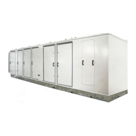
C – General Information Basic Information Dehumidifier View and Options Pic. C.1 C‐ June OMM.C.P.AA.00 2018... - Page 7 C – General Information Standard large dehumidifiers are semi‐custom: while basic concept and layout is the same, options and specific systems and components layout and location may vary from one dehumidifier to another. One of the typical dehumidifier arrangement is shown on Pic.C.1. Dehumidifier Options Indoor or outdoor installation. Note: Pic. C.1. shows outdoor model, equipped with louvers (to protect air intake and discharge openings from elements). Indoor model would have ducts connected to respective openings, no louvers would be needed. Capacity (number of compressors) – two to four compressors (see Dehumidifier Optional Arrangement below for more details): Two‐compressor dehumidifier option (models PPK070 to PPK340). Three‐compressor dehumidifier option (models PPK380 and PPK420). Four‐compressor dehumidifier option (model PPK530). Airflow/ductwork connection *. Pic. C.1 shows some options only; each option location availability depends on the dehumidifier installation (indoor or outdoor) and other options: Return Air (RA) ductwork connection ‐ top, bottom, end, sides. Supply Air (SA) ductwork connection – top, bottom, sides. Optional Min Outdoor Air (OA) ductwork connection/termination – top, sides. Optional Min Exhaust Fan (EF) and Purge Fan (PF) ductwork connections/terminations – end, sides. Optional Purge Outdoor Air (POA) ductwork connection/termination ‐ top, sides. Optional Pool Water Heating **. Dehumidifier can accommodate up to two pool water heating circuits Optional Space Heating ‐ hot water coil, electric or gas heater ***. Optional Heat Recovery (HR) circuit. Air Conditioning (AC)* – external water cooling or fluid cooler (packaged or separate). Note: Pic. C.1 shows outdoor model with “packaged” fluid cooler (mounted with the dehumidifier). “Packaged’ AC option is available for outdoor models only; alternatively, indoor and outdoor models could be fitted for separate/remote AC option – remote fluid cooler or other external cooling media source. * Some available options (tonnage, ductwork connections, AC options etc.) are shown. Refer to the submittal ...
-
Page 8: Dehumidifier External Systems Connection C
C – General Information Dehumidifier External Systems Connection Pic. C.1 shows provisions for external systems connections, including ductwork, electric power and control wires and various piping connections. CAUTION! Current manual shows general/default connections’ location. For details regarding specific dehumidifier’s connections (actual location, piping sizes and position dimensions, circuit type and flow direction etc.), refer to the dehumidifier’s submittal documentation as well as dehumidifier’s labels and stickers. Except for the condensate, all other piping systems are optional and may not be present in each dehumidifier Condensate Drain Line – bottom, side (through the dehumidifier base). NOTE. Dehumidifier MUST be equipped with a P‐trap at the condensate connection for proper operation! If dehumidifier is requested from the factory without P‐trap, one MUST be installed on site prior to dehumidifier being commissioned. Refer to the Installation Manual for details. Air Conditioning (AC) Connection. Packaged AC option (outdoor dehumidifier with outdoor fluid cooler (OAFC) incorporated with the dehumidifier), does not require piping connection to external AC system or device. Pic 1.C. shows packaged outdoor model with OAFC mounted at the end of the dehumidifier; alternatively, if requested, OAFC could be mounted on the roof of the dehumidifier. Remote (“split”) AC option (indoor or outdoor dehumidifier, connected to external cooled water/glycol system or remote fluid cooler) – side or end (through the compressor compartment wall) connection. Pool Water Heating – bottom, side. Space heating (Hot Water connection) – bottom, side. Some connection location options for both, pool and space, heating pipe lines, are limited to indoor installation only – refer to submittal documentation Space Heating (Gas Heater connection, gas line). If the dehumidifier is equipped with a gas heater (boiler, gas furnace etc.) for space heating purposes, the gas line connection is to be brought to the gas heater directly. WARNING! Gas Line. The gas line must be installed in accordance with respective device documentation (boiler, furnace, etc.) and local codes and regulations. ... - Page 9 C – General Information For two‐compressor dehumidifier, compressor compartment may have side (Fig.1; same as dehumidifier, shown on Pic. C.1) or end (Fig.2) location. End location is mostly used in higher capacity dehumidifiers. Three‐ and four‐compressor dehumidifiers (Fig.3 and Fig.4, respectively) normally have end location of the compressor compartment. Pic. C.2 Air Conditioning Options – Outdoor Air Fluid Coolers (OAFC). Basic views of standard air conditioning options are shown on Pic.C.4 (below); standard combinations of the dehumidifier and respective fluid cooler (based on their capacities) are shown in Table C.1. Note, that depending on number of factors, dehumidifier may have different cooler provided with it ‐ refer to the dehumidifier’s submittal documentation for more details. Table C.1 Standard fluid coolers used with this model of dehumidifier is NG‐V series, Dehumidifier Fluid Cooler composed of number of “two‐coils‐two‐fans” blocks, based on required PPK070 – 100 NG‐V‐12 capacity of the cooler: PPK070 – 200 NG‐V‐22 PPK140 – 300 NG‐V‐32 Fluid cooler NG‐V‐12 (Pic.C.4, Fig.1) is composed of one such block; PPK260 – 420 NG‐V‐42 NG‐V‐22 (Fig.2) composed of two such blocks etc. largest single PPK340 – 530 NG‐V‐52 fluid cooler, NG‐V‐62 (Fig.3) composed of six of them. PPK380 – 530 NG‐V‐62 PPK380 – 420 2*NG‐V‐32 As an option, each block of fluid cooler could be equipped with the pump PPK420 – 530 2*NG‐V‐42 ...
- Page 10 C – General Information Attention! Equipment Clearances! Proper clearances should be maintained for adequate airflow and heat rejection! Generally, up to 36” side and 96” top clearances are required. For more information on clearances as well as equipment dimensions and other details, refer to the submittal documentation. Pic. C.4 C‐ June OMM.C.P.AA.00 2018...
-
Page 11: Equipment Specific Data C
C – General Information Equipment Specific Data Specific information for individual dehumidifiers is provided in the following methods: Main Label (Pic. C.5): the manufacturer tag attached to the front of the dehumidifier includes the dehumidifier’s most critical data: General data including: Serial number Dehumidifier model (nomenclature) Design room conditions (air temperature and humidity) Operational data, including: Refrigeration (refrigerant type, charge, etc.) Electrical/airflow (dehumidifier voltage, CFM, etc.) Other applicable data (pool heating, space/auxiliary heating features, etc.) Labels and Stickers: attached when applicable to the exterior and interior of the dehumidifier to show: External systems connections location/direction (pool/space heating, cooling circuits, condensate) Pic. C.5 Air filter locations, quantity, and size. ... -
Page 12: Chapter D - Layout And Components
D – Layout and Components Layout and Components The general layout and components location is the same for all dehumidifiers of current type, however some may vary, based on the dehumidifier’s specific options – refer to submittal documentation. Pic. D.1 below shows all/most available options, some of which may not be present on your dehumidifier. Dehumidifier Main Components Main Blower (1) is in the main blower compartment behind or next to the Compressor Compartment (3) with Main Electric Panel (2). Based on airflow requirements, number of main blowers may vary (up to four). Two blowers could be installed either side by side or stacked on a top of each other (Pic. D.1A); four blowers’ arrangement would have two stacks, shown on Pic. 1.DA, installed side by side. Min Outdoor Air (OA) Opening (4) has a motorized damper and filter(s). The Manual OA Damper (5) is usually used to set proper amount of outdoor air intake; in some cases, it could be equipped with modulating actuator for automatic adjustment of outdoor air intake. Outdoor‐installed dehumidifier would have louver(s) (76) installed at the OA opening. Min Exhaust Fan(s) (EF) Assembly (6) (fan and motorized damper) is located on the dehumidifier’s return air side; Exhaust Air opening in outdoor‐installed dehumidifier is equipped with louver(s) (76) also. Min Exhaust Fan Assembly is hinged and could be opened for better access to the fan electric box. Dehumidifier, equipped with Heat Recovery (HR) option, would have HR glycol coils (71), installed at the Min Exhaust (EF) and Min Outdoor Air (OA) openings, and HR pump (72), installed in return air compartment. If HR option is present, Min Exhaust Fan Assembly would normally be equipped with a filter rack. If dehumidifier is equipped with Purge option, additional Purge‐exhaust fan(s) (PF) (73) with motorized damper would be installed on dehumidifier’s return air side, as well as additional (“Purge”) Outdoor Air (POA) (74) opening(s), equipped with motorized dampers, would be located directly upstream of Main Filter Rack (9). Motorized Return Air (RA) damper (75) would be located between return air side and POA opening(s). Outdoor‐ installed dehumidifier would have louvers (76) installed at the Purge‐exhaust fan and Purge Outdoor Air openings. Refrigeration Evaporator coils (7) and water/glycol Reheat coils (8) are located directly downstream of the Main Filter Rack (9). Motorized Evaporator Bypass Damper (10) is located next to the evaporator coils; it by‐passes portion of air around evaporator, thus adjusting compressor circuit operation. Some dehumidifiers, based on airflow requirement, could be equipped ... - Page 13 D – Layout and Components 11b 2 24 3 1 4 5 22 71 11a 76 10 ...
- Page 14 D – Layout and Components Compressor Compartment and Main Electric Panel (detailed; see Pic.D.1C). 15 17 25, 26 18 80 78 79 27 14 77 28 13 13 Pic. D.1C 16a 16 Compressor(s) (13), Receiver(s) (14) and other components are located within the Compressor Compartment (3): Each compressor circuit has glycol‐to‐refrigerant plate heat exchanger (16) and, common to both circuits, glycol pump (16a), that circulates water/glycol to reject compressor‐generated heat. Motorized water/glycol Reheat (79) and AC (80) valves’ opening position determines how much fluid is diverted to respective coil(s) (reheat and fluid cooler or external heat sink). If the dehumidifier has the standard pool water heating option, the compressor circuit additionally includes the coaxial pool water heat exchangers (15) and refrigeration pool water heating solenoid valves. Number of pool water heat exchanger varies based on dehumidifier type and capacity. Control sub‐panel with Main Control Board (17) and Operator Panel (18) is normally mounted on the compressor stand frame. Main Electric Panel (2) contains main blower(s) VFD (variable frequency drive) (78), main Disconnect (77), if one is installed, and other electrical and control components (contactors, fuses, control ...
-
Page 15: Control System D
D – Layout and Components Control System The dehumidifier control system is composed of sensors, spread throughout the dehumidifier, Main Control Board, Operator Panel and other electric components, located in the Main Electric Panel. Temperature Sensors (Pic. D.2): b a) Temperature sensors (thermistors) are used to monitor various temperatures (air, water, compressor, etc.); Combo sensor is used to monitor air temperature and humidity. d a Pic. D.2 Compressor operation is monitored with pressure sensors (Pic. D.3): Pressure Transducers (as main operational control and safety) and Pressure Switches (fast‐reacting backup safety). c Note. Sensors and safeties approximate location is shown on Pic. D.1B and Pic.D.3 D.1C – refer as needed. RA Combo Sensor (21) measures temperature and humidity of the pool room air (Return Air) entering the dehumidifier. It is located at the return air ductwork connection to the dehumidifier. OA Temperature Sensor (22) measures outdoor air temperature; it’s located at the OA filter rack. As an option, the combo sensor (instead of regular thermistor) can be installed at the OA intake to ... -
Page 16: Outdoor Air Fluid Cooler Layout And Components D
D – Layout and Components Outdoor Air Fluid Coolers Layout and Components . The general layout of AC options (air‐and water‐cooled) is shown on Pic.D.5 below with the outdoor fluid cooler NG‐V‐12, equipped with additional pump package (Fig.1) and NG‐V‐32 (Fig.2) as an example. While layout and main components are similar for all applicable AC options, there are some deviations (number of fans, composition, etc.). Refer to AC Options Basic View (Basic Information chapter) for additional information. 32 33 35 31 33 36 37 31 Pic. D.5 Cooling (AC) coils (31) (where heat from glycol mixture is rejected to the ambient air) is mounted onto metal frame, upstream (before) the fans (32), that pulls the air through the coils to absorb the heat. Normally, fluid cooler would have multiple coils and fans. Cooler NG‐V‐12 (Fig.1), comprised of two coils, mounted on the angle to each other, and two fans, presents a single block. Depending on the capacity, cooler could be comprised of up to six such single blocks, stacked side by side on the same frame and manifolded together – NG‐V‐32 is comprised of three such blocks. Cooler piping connections (33) are identified respectively (IN – OUT); In some cases, fluid cooler piping connection(s) may be located within pump package box (37), if fluid cooler is provided with one. Piping connection location may vary – refer to particular cooler labels, stickers, submittal and other documentation. Electric power is normally to be brought to disconnect (35) (if cooler is equipped with such), which feeds it to the electrical box (36), that contains cooler power and control apparatuses. Depending on fluid cooler specifics, location of electrical box may slightly differ; in some cases, electrical box may be incorporated into pump package or located on the opposite side of the fluid cooler. ... - Page 17 D – Layout and Components Fluid Coolers Pump Package. Fluid Coolers, if equipped with such option, would have a pump package box. Pic.D.6 below shows general layout of pump packages, used for NG‐V model fluid coolers. Note, that the package could be mounted onto the fluid cooler directly (standard) or provided separately. Pump (38) establishes glycol mixture circulation through the fluid cooler and dehumidifier; 38 Expansion tank (39) compensates for temperature‐ based glycol volume fluctuation; The pump package electrical sub‐panel (40) contains the pump package electrical power and control apparatuses. The pump package manifolds are usually equipped with pressure gauges, automatic air venting valve, draining and other valves. 40 39 Pic. D.6 D‐ ...
-
Page 18: Chapter E - Sequence Of Operation
E – Sequence of Operation Sequence of Operation The dehumidifier’s ventilation system establishes the required airflow through the dehumidifier. The control system compares air temperature and humidity to their desired values (set points) and proceeds to dehumidify, cool or heat the recirculating air. If the dehumidifier is equipped with the pool water heating option, the pool water temperature is compared to its set point and pool heating is provided if required. Set Points The control system is constantly adjusting unit operation to achieve and maintain said parameters within couple degrees/percent of the set point. Refer to the dehumidifier’s main label for the design value of control parameters, as well as the following note. Note: To ensure the dehumidifier’s most economical operation, we recommend maintaining the following relationship between pool water and room air temperatures: Room Air T = Pool Water T + 2˚F Ventilation. The main blower runs continuously, establishing required. The main blower speed is pre‐set via adjustable variable signal. Minimum Exhaust Fan (EF), if dehumidifier is equipped with such option, directs portion of return air outdoors. Like main blower, exhaust fan(s) speed is also controlled via adjustable (pre‐set) variable signal, that varies based on scheduled ventilation mode (Occupied, Non‐Occupied and Spectator) or call for Economiser Mode (as part of Air Conditioning and/or Dehumidification operation). Minimum Outdoor Air (OA) damper, if dehumidifier is equipped with such option, opens to introduce fresh outdoor air into the premise. OA damper could be equipped with ON/OFF (simple fully open – fully closed) or modulating‐controlled actuator; latter one would be controlled same way as minimum exhaust fan. Purge (Additional Exhaust) Option. Along with Min Exhaust Fan and Min Outdoor Air damper, dehumidifier could have additional set of exhaust (purge) fan(s) (PF) and purge outdoor air damper (POA), commonly referred as Purge. Purge fan(s) and OA damper(s) function is to allow for higher exhaust and fresh air amount, up to complete (100%) air changeover (when all exhaust fans and OA dampers are at their max capacities). Purge Fan(s) and Purge Outdoor Air damper(s) are controlled in the same fashion as min exhaust fans and min outdoor air. Some dehumidifiers may be equipped with additional Return Air damper: it closes in event of complete air changeover, separating return air side of dehumidifier from supply side (refer to Layout and Components chapter, as needed, for respective devices’ location). Complete air changeover, triggered manually, is known as Purge Mode. Note. Externally installed Exhaust Fan(s) and Outdoor Air damper(s) could be also controlled by the ... -
Page 19: Heat Recovery Option E
E – Sequence of Operation Heat Recovery Option. Dehumidifiers, packaged with Minimum Exhaust Fan and Minimum Outdoor Air damper, could also have additional Heat Recovery (HR) closed‐loop glycol system. Heat Recovery loop (see Pic. E.1 below) consists of two coils (air‐to‐glycol heat exchangers) and a pump, establishing glycol circulation between them. One coil, installed at exhaust air opening, recovers portion of exhausted air energy, another coil, installed at outdoor air intake, transfers this captured energy to entering outdoor air. Pic. E.1 Space Heating When premise air temperature drops below the set point, the dehumidifier control system issues a call for Space Heating Mode and engages space heater (electric heater, hot water coil with valve, gas boiler etc.) by sending space heating signal, respective to space heater control type ‐ on/off, variable (0‐10VDC), etc. Air Conditioning, Dehumidification and Pool Heating. When premise air temperature goes over (exceeds) its set point, the dehumidifier control system issues a call for Air Conditioning Mode. Respectively, when premise air humidity goes over (exceeds) its set point, the dehumidifier control system issues a call for Dehumidification Mode. In some instances, these calls may co‐exist. To execute Dehumidification or Air Conditioning (Cooling) mode, control system, depending on current conditions, would resort to available means of cooling or dehumidification. Economiser Mode Option. Note. Economiser Mode requires dehumidifier to be equipped with full (min and additional) exhaust and outdoor air options! If outdoor air is dry and/or cool, it could be used to dehumidify and/or cool the premise. In this case, on call for Dehumidification or Air Conditioning mode(s), control system would simply increase exhaust fan(s) speed signal to direct more stale return air outside and bring in more outdoor (dry/cool) air in, thus reducing supply air humidity and/or temperature (as needed). E‐ ... - Page 20 E – Sequence of Operation Compressor(s) Whenever the compressor operates, the evaporator is always dehumidifying and cooling the return air. The heat removed from the air at the evaporator, as well as the heat from the compressor's action, must be rejected to one of three heat sinks: room (premise) air, pool water (if applicable) or outdoors. The control system will direct the heat to where it is needed based on room (air and pool water temperature) conditions: If room air is needed to be warmed up – more heat is diverted towards reheat coil; If pool water is needed to be warmed up – more heat is diverted towards pool heating coaxial heat exchanger (if dehumidifier is equipped with this option). Rest of the heat (if any) is diverted towards outdoors (outdoor fluid cooler, external heat sinks etc.) Compressor Circuit Operation Piping schematic for compressor circuit is shown on Pic. E.2. Schematic shows single compressor circuit (second compressor circuit schematic is the same) and common to both compressor circuits’ glycol cooling circuit. Circuit operation below applies to both compressors; compressors are staged – if first compressor’s capacity is not enough to satisfy the call, second compressor will be engaged after certain time delay. When a demand requires the compressor to operate, the following sequence occurs: Once blower operation, related safeties and timers are confirmed by the control system, following occurs: Compressor glycol pump starts, establishing cooling glycol/water flow through the compressor fluid circuit ‐ plate heat exchanger(s) and fluid cooling coils (reheat and/or fluid cooler or external cooling source). Pump down solenoid valve opens and once pressure stabilizes, the compressor starts. Based on the premise air temperature, the Reheat and AC valves would adjust their opening position (open more/close more), reducing or increasing fluid flow to and through the respective fluid coils: Reheat and AC valves are controlled in the same manner with opposite effect: for example, when AC valve opens 10% more, Reheat valve closes 10% more etc. if more heat is required by the room air, the Reheat valve opens more, and AC valve closes more, thus diverting more fluid to the reheat coils (heat is rejected to the premise); if more cooling is required by the room air, the AC valve opens more, and Reheat valve closes more, ...
- Page 21 E – Sequence of Operation Pic. E.2 E‐ ...
-
Page 22: Chapter F - Interface And Communication
F – Interface and Communication Interface and Communication Touch Display Operator Panel The Touch Display Operator Panel (OP), shown on Pic. F.1, is used as a main interface between the dehumidifier and operator. The same OP can be located in the dehumidifier main electric panel (default; used as a local OP) or installed remotely from the dehumidifier •... -
Page 23: Alarms F
F – Interface and Communication Alarms If the dehumidifier control system detects abnormal or unsafe for further operation situation, it issues Alarm (notification of such situation accompanied by respective component or entire dehumidifier stoppage and/or lockout) or Alert (notification of minor abnormal situation without any devices’ stoppage or lockout). All alarms and alerts are recorded and can be viewed/cleared via the Touch Display OP: ✓... -
Page 24: Remote Communication
F – Interface and Communication Remote Communication Although dehumidifier is designed to operate as a self-controlled device (not requiring any external control), communication between the dehumidifier and external control and monitoring systems is possible. Virtual-Tech Virtual-Tech is an online tool (also referred to as Web Monitor), that allows for remote communication to the dehumidifier for various purposes such as monitoring, data collection, parameters adjustment, and notifications. - Page 25 F – Interface and Communication This page is left blank...
-
Page 26: Chapter M - Basic Maintenance
M – Basic Maintenance Basic Maintenance Although PoolPak equipment is built for minimal service downtime, periodic preventative maintenance is required to ensure maximum reliability, safety, and operating efficiency. WARNING! To ensure equipment longevity and proper and efficient operation, the dehumidifier and its auxiliary systems and devices (outdoor condenser, fluid cooler, boiler package, etc.) must be maintained properly... -
Page 27: Routine Maintenance Program M
M – Basic Maintenance • Pool Water Chemistry. Incorrect pool water chemistry (improper pH level or high concentration of chlorine, sea salt or other corrosive additives etc.) can result in equipment premature wear or malfunction (let alone poor air quality in the pool and potential health issues) and will void the equipment warranty. Refer to pool water quality standards;... -
Page 28: Specific Components Maintenance M
M – Basic Maintenance Specific Components Maintenance Actual maintenance plan may vary from installation to installation, yet there are several key components from maintenance prospective. If needed, contact respective component manufacturer for additional maintenance information. Filters • Ensure air filters are clean. Dirty air filters will negatively affect dehumidifier performance and lifetime •... - Page 29 M – Basic Maintenance Special Maintenance Tasks. Fluid Cooler Winterization. Normally fluid coolers are used in the systems, filled with glycol mixture to prevent the system and the fluid cooler from freezing and, potentially, rupturing, when exposed to temperatures below freezing point. When fluid cooler is used with media that, when exposed to low temperatures, could freeze (water or lower- percentage glycol mixture), one way to protect the equipment is to drain it (also known as “winterization”...
-
Page 30: Chapter W - Warranty
– travel time, diagnostic time, per diems, truck charges, etc. are not covered under this warranty. Two Year Parts Warranty If any factory installed part supplied by PoolPak® LLC fails because of a defect in workmanship or material prior to the completion of the 24 month from date of shipment, PoolPak®... - Page 31 Replacement Part Warranty If a replacement part provided by PoolPak® LLC under this warranty fails due to a material defect prior to the end of the Two Year Parts Warranty (or the end of the extended warranty period if applicable) or 12 months from date of the replacement part shipment, whichever comes first, PoolPak®...
- Page 32 W – Warranty Force Majeure PoolPak® LLC will not be liable for delay or failure to provide warranty service due to government restrictions or restraints, war, strikes, material shortages, acts of God or other causes beyond PoolPak® LLC control. Optional Five Year Compressor Warranty This extended warranty must be purchased before the shipment of the equipment.
- Page 33 This extended warranty must be purchased before the shipment of the equipment. PoolPak® LLC will provide a replacement of driveline components (listed below as Driveline Components) for 60 months from the date of shipment provided the factory installed component fails as a result of manufacturing defect and is returned to the factory with transportation prepaid.
Need help?
Do you have a question about the PPK070 - 100 and is the answer not in the manual?
Questions and answers