Table of Contents
Advertisement
Quick Links
Advertisement
Table of Contents

Related Manuals for PoolPak R-410A AW Series


Summary of Contents for PoolPak R-410A AW Series
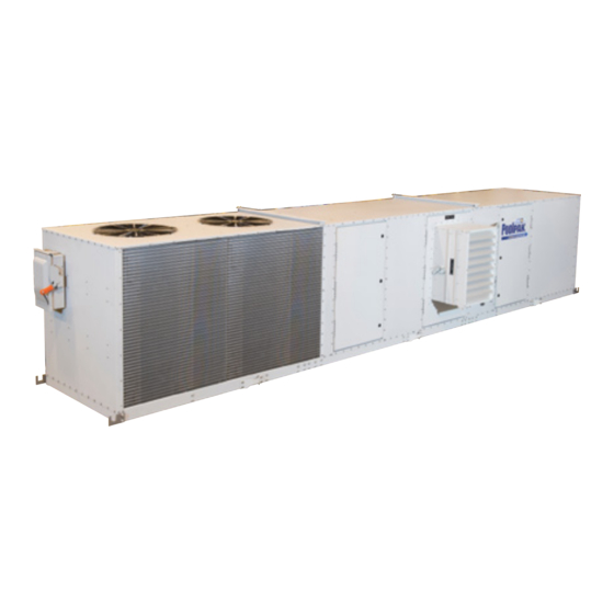
- Page 1 POOLCOMPAK R-410A AW/HCD SERIES ROOFPAK SERIES HCD (High Capacity Dehumidifier) AW (Air and Water) Horizontal (H) and Vertical (V) Configurations Engineering Guide EGW06-PCPEG-20140813 Packaged Natatorium Environment Control System PoolComPak (PCP) RoofPak (AWH/ HCDH only)
- Page 2 The Leader in Indoor Pool Dehumidification 3491 Industrial Drive . York, PA 17402 . USA . 800-959-7725 . Fax 717-757-5085 www.poolpak.com for more information:...
-
Page 3: Table Of Contents
TABLE OF CONTENTS SECTION I: INDOOR POOL DESIGN ............................1 Introduction ....................................1 Creating an ideal environment for indoor pool facilities......................1 Operating Cost ..................................1 Application ....................................1 Moisture Loads ..................................1 Effects of Moisture ................................... 1 Indoor Air Quality ..................................1 Occupant Comfort .................................. - Page 4 Housed Blower ..................................14 Cupronickel Water Heat Exchanger ............................. 14 Technical Summary .................................. 15 Dimensional Data ..................................15 RoofPak Weights ..................................15 SECTION III: PERFORMANCE AND SIZING ..........................16 PoolComPak™ Performance ..............................16 PoolComPak™ AW (AWV, AWH) Performance ........................16 PoolComPak™...
- Page 5 SECTION V: OPERATION ................................43 ECC-PCP Remote Interface Unit ..............................43 Status Display ..................................43 Set Point Change Menu ................................44 Air Temperature ..................................44 Relative Humidity .................................. 44 Pool Temperature ................................. 44 Recommendations ................................44 Purge Mode Control Menu ............................... 45 Detailed Status Menu ................................
- Page 6 Figure 3-1 AW/HCD Horizontal Unit Elevation and End Views ....................18 Figure 3-2. AW/HCD Vertical Unit Elevation and Plan Views....................... 19 Figure 3-3. Air-Cooled Condenser (PoolPak) - Isometric Views ....................24 Figure 3-4. Air-Cooled Condenser (Bohn) - Elevation Views ....................... 24 Figure 3-5.
-
Page 7: Section I: Indoor Pool Design
The PoolPak™ System utilizes an environmental control package designed to meet all special needs of the indoor pool environment, while reducing energy usage and building maintenance costs. -
Page 8: Occupant Comfort
National Spa and Pool Institute standards. Indoor Pool For more information, review the Controling Chloramines with Proper Chlorine Management chapter in the Water Chemistry publication in the online PoolPak™ Educational Library. EGW06-PCPEG-20140813... -
Page 9: Equipment Choices
Section I: Indoor Pool Design Table 1-2. Recommended Pool Water Chemistry Pool Ideal Ideal Total Chlorine (ppm) 1.0 - 3.0 3.0 - 5.0 Free Chlorine (ppm) 1.0 - 3.0 3.0 - 5.0 Combined Chlorine (ppm) Bromine (ppm) if applicable 2.0 - 4.0 3.0 - 5.0 7.4 - 7.6 7.4 - 7.6... -
Page 10: Hybrids
ROOM AIR DISTRIBUTION All PoolPak™ models provide continuous air recirculation, and with a good air distribution system, will promote uniform space conditions. To remove the required moisture and maintain controlled conditions, it is essential that there be adequate air movement and distribution in the natatorium. -
Page 11: Figure 1-1. Perimeter Air Distribution
SUPPLY AIR SUPPLY AIR BLOWING SUPPLY AIR SUPPLY AIR BLOWING UP TO SKYLIGHTS DOWN FROM SOFFIT DUCTS TO SKYLIGHTS FROM BELOW-GRADE COVERING WINDOWS AND DUCTS COVERING WINDOWS POOLPAK MOISTURE-EXPOSED AREAS AND MOISTURE-EXPOSED DEHUMIDIFICATION POOLPAK AREAS SYSTEM DEHUMIDIFICATION SYSTEM ALL_AirDistributionDown_20131220.eps ALL_AirDistributionUp_20131220.eps The warm, dry air should be directed over outside walls, windows and other surfaces susceptible to condensation, or it can be directed down the center of the room blowing air toward the surfaces prone to have condensation. -
Page 12: Return Air
PoolPak™ System. Return grilles can be placed high in the space to reduce return ductwork, however removal of Chloramines from the occupied area has become much more of a design consideration and so low returns are favored by poolroom designers. -
Page 13: Other Airside Considerations
Ducts can be fabric, aluminum, PVC, or galvanized steel. Even though “dry air” is being supplied back to the pool, do not use duct board or similar materials. If the PoolPak™ unit is installed in an area that is below the natatorium’s dew point temperature, the ducts may require insulation, pitching and drainage. -
Page 14: Section Ii: Principles, Functions, And Features
System’s major function is to dehumidify the pool enclosure air through a vapor compression cycle. During this cycle the PoolPak™ System recycles the sensible and latent heat and places it back into the pool water and air as needed. This recycling process saves money and keeps your pool environment efficient and safe. -
Page 15: Room Dew Point Control
“grains of moisture per pound of dry air” and is directly related to the dew point temperature. The ECC-PCP uses dew point control to operate the PoolPak™ unit and maintain the moisture level below the setpoint. The space dry bulb temperature and relative humidity determine the dew point temperature. By varying the space temperature and space relative humidity set points, the dew point set point is changed. -
Page 16: Ecc-Pcp Control System
Section II: Principles, Functions, and Features If pool water heating is required (AWH models only), the hot gas flows into a pool water condenser, where it adds energy to the incoming pool water. This heats the pool water while the refrigerant is condensed into a warm liquid. If space cooling is called for, the refrigerant flows to the auxiliary air conditioning condenser bypassing the air reheat coil and pool water condenser and allowing cool air from the evaporator coil to provide space ECC-PCP CONTROL SYSTEM... -
Page 17: Networking Multiple Units
Section II: Principles, Functions, and Features NETWORKING MULTIPLE UNITS ECC-PCP networking allows up to four PoolComPak™ units to be connected together. The units will work with each other to control water temperature, air temperature, and relative humidity. Networked PoolComPak™ units have all the features of standard PoolComPak™... -
Page 18: Roofpak System
• Archival • Electronic • Warehousing/storage Unit Selection software program PoolPak™ International LLC maintains a computerized software selection program. Information required for the PoolPak™ Engineering program can be found in the PoolComPak Selection Input Data form found in the online Library. -
Page 19: Roofpak Series (Hcdh/Awh)
Section II: Principles, Functions, and Features ROOFPAK SERIES (HCDH/AWH) PoolPak™ has taken their most popular PoolComPak™ configuration and repacked it as a self-contained, all-in- one dehumidification system. This product comprises the RoofPak Series. This offering merges a highly reliable PoolComPak™ AWH or HCDH base system with an integral air-cooled condenser and either an integral gas furnace or an electric heater. -
Page 20: Totally Enclosed, Fan Cooled (Tefc) Motors
Section II: Principles, Functions, and Features Totally Enclosed, Fan Cooled (TEFC) Motors • Protects fan motors from corrosive air stream • Extends motor life/prevents premature failure • Reduces system maintenance Unique Outside Air System • Houses adjustable louvers and filter •... -
Page 21: Technical Summary
With Integral Gas or Electric Heat and With Integral ACC 3,700 AWH/HCDH 3500/4000 With No Integral Auxiliary Heat and With Integral ACC 2,700 RoofPak weights are also included with the RoofPak Generic Product Drawings found in the Engineering Library section of the PoolPak™ website. EGW06-PCPEG-20140813... -
Page 22: Section Iii: Performance And Sizing
SECTION III: PERFORMANCE AND SIZING POOLCOMPAK™ PERFORMANCE Detailed performance and dimensional information are provided in the PoolPak™ Selection Software PoolComPak™ AW (AWV, AWH) Performance Table 3-1. PoolComPak™ AW Performance Summary Pool water Condenser Performance at 82°F Air and 80°F Water... -
Page 23: Poolcompak™ Hcd (Hcdv, Hcdh) Performance
Section III: Performance and Sizing PoolComPak™ HCD (HCDV, HCDH) Performance Table 3-2. PoolComPak™ HCD Performance Summary Performance at 82°F Air and 80°F Water Moisture removal Sensible Cooling ACC Max. Heat Model HCD Return Air CFM Return Air RH (%) (lbs/hr) Capacity (MBH) Rejection (MBH) 10.2... -
Page 24: Poolcompak Unit Dimensions
Section III: Performance and Sizing POOLCOMPAK UNIT DIMENSIONS The latest detailed unit dimensional data may be found in the PoolComPak™ Series AWH/HCDH, AWV/HCDV All Models R-410A Dimensional Drawings publication (EG6_Dim_All) which can be downloaded from in the PoolPak™ Engineering Library (www.poolpak.com). PoolComPak™ Horizontal Dimensions Table 3-3. -
Page 25: Poolcompak™ Vertical Dimensions
Section III: Performance and Sizing PoolComPak™ Vertical Dimensions Table 3-4. AW/HCD Vertical Unit Overall Dimensions Model Number 1200 1400 1800 2600 3500 4000 Basic (W) 32.1 32.1 32.1 38.8 38.8 49.6 68.2 68.2 Width Side OA (Wo) 39.0 39.0 39.0 45.7 45.7 56.5... -
Page 26: Hot Water Coil Capacities
Section III: Performance and Sizing HOT WATER COIL CAPACITIES Table 3-5. Hot Water Coil Capacities Vertical (AWV, HCDV) Models 1 Row Hot Water Coil Flow Rate Range (GPM) Heating Capacity Range (MBH) Model 0550 0800 1200 1400 1800 2600 3500 4000 Horizontal (AWH, HCDH) Models 1 Row Hot Water Coil Flow Rate Range (GPM) -
Page 27: Poolcompak Outside Air Damper Size
Section III: Performance and Sizing POOLCOMPAK OUTSIDE AIR DAMPER SIZE Table 3-6. PoolComPak™ Outside Air Damper Size Outside Air (OA) Opening Model# Damper Code OA CFM Range Location Size (in.) PoolComPak Vertical AWV/HCDV OA-TR V550/800/1200 A, 14 x 10 0-800 Left OA-LT OA-TR... -
Page 28: Refrigerant
Section III: Performance and Sizing REFRIGERANT Table 3-7. Factory Refrigerant R410A Charge Unit Factory Charge ( R410A) Air Cooled Condenser Water Cooled Condenser (ACC) (WCC) Model 0550 0800 1200 1400 1800 2600 3500 42 (81) 1 (0) 4000 44 (83) 1 (0) 1 Factory charge for remote ACC option does not include refrigerant for either ACC or lineset. -
Page 29: Remote Air-Cooled Condenser (Acc)
Section III: Performance and Sizing REMOTE AIR-COOLED CONDENSER (ACC) Table 3-8. Remote ACC Performance Chart Note: Below table contains the piping sizes of the remote ACC stub-outs. Additional field piping may be needed to make the transition from the connections to correct refrigeration lineset sizing (See Table 4-3.) Unit Vapor Liquid... -
Page 30: Figure 3-3. Air-Cooled Condenser (Poolpak) - Isometric Views
Section III: Performance and Sizing Figure 3-3. Air-Cooled Condenser (PoolPak™) - Isometric Views *ALL DIMENSIONS ARE IN INCHES SINGLE FAN DUAL FAN PCP_EG_ACC_PoolPakMfgr_20140122.eps Figure 3-4. Air-Cooled Condenser (Bohn) - Elevation Views ALL DIMENSIONS ARE IN INCHES 45.4 42.3 49.1 20.25 0.875 DIA. -
Page 31: Electric Duct Heater
Section III: Performance and Sizing ELECTRIC DUCT HEATER General Duct Heater Information Power wiring should incorporate properly sized fuses or motor rated circuit breakers. A disconnect must be fitted within easy access and sight of the unit. Supply voltage must be maintained within +/- 10% of design voltage on both single and three phase units. -
Page 32: Section Iv: Installation
SECTION IV: INSTALLATION PCP INSTALLATION INTRODUCTION Installation requires the unit to be placed on a roof mounted curb, the mechanical room floor, an appropriate location in the pool room, or outside on an equipment housekeeping pad. Isolation pads should be placed under the unit to minimize transmission of noise due to unit operation. -
Page 33: Handling
The condensate may be piped to a drain or returned to the pool if local codes allow. If returned to the pool, the condensate should be piped to the skimmer. PoolPak™ International recommends neither for, nor against, the practice of returning condensate to the pool. The overflow drain should be piped in a similar fashion. The installer should review the local codes prior to making the decision of where to dispose of the condensate. -
Page 34: Curb Mounting
Section IV: Installation CURB MOUNTING Illustrated in figure 4-2 is a curb that has been designed specifically for the PoolComPak™ product line. The outside dimensions of the curb are such that the base of PoolComPak™ extends over the edge of the curb all the way around. This aids in preventing rainwater from getting between the base of the PoolComPak™... -
Page 35: Integral Gas Furnace Option (Roofpak Only)
Section IV: Installation Table 4-1. Horizontal PoolComPak™ Curb Dimensions Model#: 550/800/1200 1400/1800 2600/3500/4000 2600/3500/4000 Fan Size: 9”x7” Blower 12”x9” Blower 12”x9” Blower 18”x13” Blower Overall Dimensions 58.5 70.5 90.5 90.5 32.3 42.5 42.5 42.5 Return Duct Chase 14.6 15.4 15.4 22.2 25.5 32.7... -
Page 36: Ecc-Pcp Controls Field Wiring
A ¾” hole must be drilled for the 6-conductor cable which connects the remote interface unit to the PoolPak™ unit. The below is specific mounting instructions that correspond to the mounting schematic below: 1. -
Page 37: Cold Surface Temperature Sensor (2)
Section IV: Installation COLD SURFACE TEMPERATURE SENSOR (2) This sensor is used to measure the temperature of the coldest surface in the pool enclosure. The sensor is an aluminum bar 1” long by ¼” square with a clearance hole for a number 8 screw and two 6” wires on one end. When the temperature of the surface drops to within 5 F of the space air dew point the humidity set point will be automatically reset downward to help prevent condensation on the cold surface. -
Page 38: Outside Air Temperature Sensor (Economizer Option Only) (4)
Section IV: Installation WARNING! When economizer option is selected, adequate exhaust capacity via a separate fan must be specified to ensure the natatorium pressure remains slightly negative. Failure to specify adequately sized exhaust system may result in damage to structure and pool odors may be forced into other areas of the building. OUTSIDE AIR TEMPERATURE SENSOR (ECONOMIZER OPTION ONLY) (4) The outside air temperature sensor is installed only when the outside air economizer option is included. -
Page 39: Auxiliary Pool Water Heating System (Awh Model Only*) (6)
Section IV: Installation AUXILIARY POOL WATER HEATING SYSTEM (AWH MODEL ONLY*) (6) The auxiliary pool water heating system is provided by others. Typically a gas fired or electric pool water heater is used. The ECC-PCP provides a dry contact closure that signals a need for auxiliary water heating. The contacts of the ECC- PCP may be connected directly to the heater’s control circuit provided the circuit is 24 VAC maximum and the current does not exceed 1 amp inductive. -
Page 40: Building Fire Control System (9)
Section IV: Installation BUILDING FIRE CONTROL SYSTEM (9) The ECC-PCP can receive a contact closure signal from a building fire control system. This input of the controller must be connected to dry (voltage free) contacts only. When this input receives a contact closure, the PoolComPak™ unit compressor and fan will be shut down and the remote interface unit will show an alarm condition. -
Page 41: Pool Water Piping (Awh And Awv Models Only*)
Condensate may be returned to the pool (if local codes allow), but PoolPak™ International neither recommends nor disapproves this practice. The installer should check local codes prior to making this decision. Condensate must be filtered prior to being returned to the pool. -
Page 42: Condensate Drains
Section IV: Installation Figure 4-8. Typical Pool Water Piping Diagram (AWH and AWV Model Only)* UNIONS CHEMICAL POOL FEEDER AUXILIARY BALL CHECK POOL WATER VALVES VALUE HEATER LOCKING GLOBE DRAIN VALVE UNIONS POOL WATER LOCKING TEMP. SENSOR GLOBE VALVE BALL Flow VALVES POOL... -
Page 43: Water Cooled Condenser
Section IV: Installation Figure 4-9. AWH and HCDH Condensate Trap REMOVABLE CLEANOUT AWH OR HCDH UNIT OPEN TEE FOR VENT UNIT BASE PLUG THE UNUSED CONNECTION 4 INCHES MINIMUM OR MAX NEGATIVE STATIC WITH SUITABLE PRESSURE (INCHES W.C.) + 1 INCH PVC PLUG 2 INCHES MINIMUM OR 1/2 MINIMUM SCHEDULE 40 PVC... -
Page 44: Multiple Units
Section IV: Installation Figure 4-10. Remote ACC Installation Around Walls or Obstructions AIR FLOW MIN. * W”=Total width of the condenser ALL_WallsorObstructions_20131111.eps Multiple Units For units placed side by side, the minimum distance between units is the width of the largest unit. If units are placed end to end, the minimum distance between the units is 4 feet. -
Page 45: Decorative Fences
Section IV: Installation Decorative Fences Fences must have 50% free area, with 1 foot undercut, a “W” minimum clearance, and must not exceed the tops of the unit. If these requirements are not met, the unit must be installed as indicated for “Units in Pits”. Figure 4-13. -
Page 46: Sizing
Section IV: Installation Sizing: • The lines must be sized and routed so that oil is carried through the system. Using smaller lines than recommended will give excessive pressure drops, resulting in reduced capacity and increased power consumption. Oversized lines could result in an oil flow problem within the system and possible compressor damage. -
Page 47: Refrigerant And Oil Charging
Section IV: Installation Refrigerant and Oil Charging: • PoolPak™ units are shipped with the required charge for self contained operation only. The remote ACC option does NOT provide the refrigerant charge or oil required for the ACC and line sets. - Page 48 Above chart is for lineset length less than 100 ft and ACC located less than 50ft above unit or 20ft below unit. Failures due to a piping layout not within these limits nor receiving prior PoolPak™ Factory approval will not be covered under PoolPak™ warranty.
-
Page 49: Section V: Operation
SECTION V: OPERATION ECC-PCP REMOTE INTERFACE UNIT Figure 5-1. RIU Keypad PCP_EG_StraightOnKeypadAnnotated_20121204.eps The ECC-PCP Remote Interface Unit (RIU) is designed around the Carel pGD0, 4-line x 20 character, backlit, LCD display module. The RIU displays are accessed through six backlit selection buttons. They consist of a Return/ Enter Key, Up Key, Down Key, Program Key, Alarm Key, and Escape Key, as shown above. -
Page 50: Set Point Change Menu
Section V: Operation • DEHUMID (SURFACE) Indicates the space requires dehumidification. The word SURFACE indicates that the unit is temporarily lowering the dew point set point to minimize condensation at the cold surface temperature sensor. • ECONOMIZER MODE Indicates the unit is cooling the space with outside air. ECONOMIZER MODE is only shown if the optional economizer system is present. -
Page 51: Purge Mode Control Menu
Section V: Operation PURGE MODE CONTROL MENU CAUTION It is the user’s responsibility to use this feature properly to prevent freeze damage to downstream equip- ment. 100% outside air at below freezing conditions has the potential to cause serious damage. Purge Mode causes the unit to force the optional, field-provided, economizer dampers and fan to full open, introducing large quantities of outside air to the space. -
Page 52: Ecc-Pcp Network Operation
Section V: Operation ECC-PCP NETWORK OPERATION Networked ECC-PCP units operate in a MASTER/SLAVE environment. This means that one unit (master) determines heating, cooling, and dehumidification requirements and broadcasts them on the network to the other units (slaves). This ensures that all units work together instead of against other. Each networked unit contains all sensor and controls necessary for independent operation and is capable of acting in the master role. -
Page 53: Changing Set Points
Section V: Operation water temperature setting, this parameter, when set to NO, requires this unit to be displayed on the control panel before changing any of the set points. The other screens for Pool Water Temperature Control, Staged Dehumidification, and Stage 2 Offset are not available when this parameter is set to NO. -
Page 54: Analog Inputs
Section V: Operation The following digital output screens are available: • Supply Fan • Compressor • Bypass Solenoid • Water Heating Solenoid • Reheat Solenoid • AC Solenoid • Aux Water Heat • Alarm Output • ACC Run Signal • Economizer •... -
Page 55: Humidity Control
Section V: Operation Humidity Control This menu contains parameters that configure the humidity control routines of the dehumidifier. Water Temp Ctrl This menu contains parameters that configure the compressor based water heating system of the dehumidifier. • Water Heat First: This parameter indicates whether the control routine will use the compressor for water heating when there is no dehumidification requirement. -
Page 56: Maintenance
Calcium Acid (ppm) 30 - 50 30 - 50 • PoolPak™ International recommends daily logging of your pool water chemistry. MAINTENANCE AND YOUR POOL WATER CHEMISTRY IS IMPORTANT TO PROTECT YOUR WARRANTY RIGHTS. MONTHLY MAINTENANCE • Air Filters, inspect and replace or clean as applicable. Dirty filters restrict air flow and can cause improper unit operation. -
Page 57: Section Vi: Wiring
SECTION VI: WIRING AUXILIARY AIR & POOL WATER HEATER CONNECTIONS FOR MULTIPLE UNIT INSTALLATION Figure 6-1. Auxiliary Air and Pool Water Heater Connections for Multiple Units AWH_EG_Connections_20121204.eps EGW06-PCPEG-20140813... -
Page 58: Auxiliary Air & Pool Water Heater Connection For A Two Pool Installation
Section VI: Wiring AUXILIARY AIR & POOL WATER HEATER CONNECTION FOR A TWO POOL INSTALLATION Figure 6-2. Auxiliary Air and Pool Water Heater Connections for Two Pool Installations AWH_EG_ConnectionstoPool_20121204.eps EGW06-PCPEG-20140813... -
Page 59: Field Wiring
Section VI: Wiring FIELD WIRING Figure 6-3. Field Wiring Diagram PCP_EG_FieldWiringDiagram_20121204.eps EGW06-PCPEG-20140813... -
Page 60: Fire Control System Connection
Section VI: Wiring FIRE CONTROL SYSTEM CONNECTION Figure 6-4. Fire Control System Connection PCP_EG_FirecontrolSysConnection_20121204.eps EGW06-PCPEG-20140813... - Page 61 Section VI: Wiring This page intentionally left blank EGW06-PCPEG-20140813...
- Page 62 The Leader in Indoor Pool Dehumidification 3491 Industrial Drive . York, PA 17402 . USA . 800-959-7725 . Fax 717-757-5085 www.poolpak.com for more information: EGW06-PCPEG-20140813...
Need help?
Do you have a question about the R-410A AW Series and is the answer not in the manual?
Questions and answers