
Related Manuals for BodyCraft SW-95.0225-G


Summary of Contents for BodyCraft SW-95.0225-G
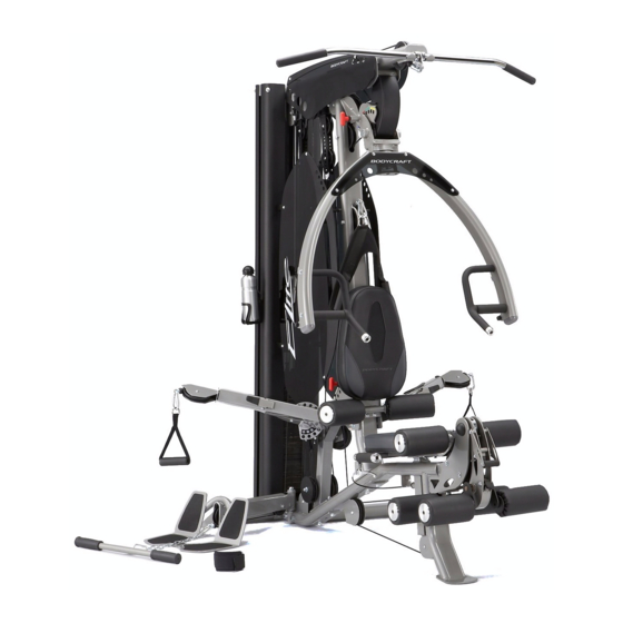
- Page 1 Assembly and Operating Instructions max. 150 kg SW-95.0225-G ~320 Min. 278 kg/329 kg L 177 | B 158/215 | H 210 SW950225.01.02 SW-95.0226 Elite Multi-Gym SW-95.0225-G / SW-95.0226...
- Page 2 Elite...
-
Page 3: Table Of Contents
Content GENERAL INFORMATION Technical Data Personal Safety Set-Up Place ASSEMBLY General Instructions Scope of Delivery - Multi-Gym Assembly - Multi-Gym Scope of Delivery - Leg Press Assembly - Leg Press STORAGE AND TRANSPORT General Instructions TROUBLESHOOTING, CARE AND MAINTENANCE General Instructions Faults and Fault Diagnosis Cable Adjustment 4.3.1 Extend or Shorten the Cable... - Page 4 With BodyCraft® fitness equipment, the focus is on what sport is all about: maximum performance! Therefore, the equipment is developed in close consultation with athletes and sports scientists.
- Page 5 ABOUT THIS MANUAL Please carefully read the entire manual before installation and first use. The manual will help you to quickly set up the system and explains how to safely use it. Make sure that all persons exercising with the equipment (especially children and persons with physical, sensory, mental or motor disabilities) are informed about this manual and its contents in advance.
-
Page 6: General Information
GENERAL INFORMATION Technical Data Dimensions and Weight Multi-Gym Elite - SW-95.0225-G Packaging dimensions (L x W x H) approx.: Box 1: 178 cm x 70 cm x 24 cm Box 2: 119 cm x 105 cm x 23 cm Box 3: 197 cm x 38 cm x 10 cm... -
Page 7: Personal Safety
Personal Safety DANGER ⚠ Before you start using the equipment, you should consult your physician that this type of exercise is suitable for you from a health perspective. Particularly affected are persons who: have a hereditary disposition to high blood pressure or heart disease, are over the age of 45, smoke, have high cholesterol values, are overweight and/or have not exercised regularly in the past year. -
Page 8: Set-Up Place
Set-Up Place WARNING ⚠ Do not place the equipment in main corridors or escape routes. ⚠ CAUTION Choose a location in which to place the equipment such that there is enough free space/ clearance to the front, the rear and to the sides of the equipment. The training room should be well ventilated during training and not be exposed to any draughts. -
Page 9: Assembly
ASSEMBLY General Instructions ⚠ DANGER Do not leave any tools, packaging materials such as foils or small parts lying around, as otherwise there is a danger of suffocation for children. Keep children away from the equipment during assembly. ⚠ WARNING Pay attention to the instructions attached to the equipment in order to reduce the risk of injuries. -
Page 10: Scope Of Delivery - Multi-Gym
Scope of Delivery - Multi-Gym The scope of delivery consist of the following parts. At the beginning, check whether all parts and tools belonging to the device are included in the scope of delivery and whether damage has occurred. In the event of complaints, the contractual partner must be contacted directly. CAUTION ⚠... - Page 12 Pre-assembled: Elite...
-
Page 13: Assembly - Multi-Gym
Assembly - Multi-Gym Before assembly, take a close look at the individual assembly steps shown and carry out the assembly in the order given. NOTICE First loosely screw all parts together and check that they fit properly. Tighten the screws using the tool only when you are instructed to do so. - Page 14 Step 2: Assemble Top Frame and Weight Stack Attach the two GUIDE RODS (6) to the stack mount welded to the REAR STABILIZER (2) using two 3/8” X 3/4” HEX THREADED BOLTS (180). Tighten these bolts. Slide one RUBBER CUSHION (110) onto each GUIDE ROD (6) and push to the bottom. Apply silicone lubricant to the GUIDE RODS (6), then CAREFULLY slide a total of 19 WEIGHT PLATES (59) one at a time onto the GUIDE RODS (6) making sure to orient the selector holes toward the side and bottom.
- Page 16 Step 3: Assemble Cable Arm ࣑ ATTENTION Remember to keep all BOLTS loose to ensure the holes will align easily. Attach the CABLE ARM ASSEMBLY (18) to the MAIN FRAME (1), using two 1/2” X 3-1/4” HEX BOLTS (130) four 1/2” SMALLER WASHERS (161) and two 1/2” NYLA-NUTS (169). Attach CABLE ARM ASSEMBLY (18) to the CABLE ARM CONNECTOR (19), using two 3/8”...
- Page 18 Step 4: Assemble Leg Extension and Seat Attach the R and L LEG EXTENSION ARMS (21R & 21L) along with RATCHET (32) to the preassembled LEG EXTENSION ASSEMBLY (20) as shown. Secure by tightening both of the preinstalled 5/16” X 1/2” SET SCREW (157), one located in the RATCHET (32) and one in the R LEG EXTENSION ARM (21R).
- Page 20 Step 5: Assemble Press Arm Secure the PLASTIC COVER (74) to the front of the PRESS ARM SUPPORT (9) using one M5 X 63L SCREW (153). Attach the PRESS ARM SUPPORT (9) to the TOP FRAME (4) by aligning the holes and inserting the AXLE (35).
- Page 21 Step 6: Assemble Seat Back Adjuster and Leg Holder Attach the SEAT BACK ADJUSTER (13) to the FRONT UPRIGHT (3), using one 3/8” X 5-1/4” HEX BOLT (133), two 3/8” LARGER WASHERS (163) and one 3/8” NYLA-NUT (170). ࣑ ATTENTION Tighten this bolt until the SEAT BACK ADJUSTER (13) is snug against the FRONT UPRIGHT (3) to eliminate play.
- Page 22 Step 7: Install Top Cable NOTICE Assemble cables and pulleys simultaneously. See Fig. 1: Insert the Bolt-end of the TOP CABLE (82) through the bottom of the front slot of the TOP FRAME (4), then over Pulleys T1 and T2 as shown. Secure each pulley using one 3/8” X 109.5L FLAT PIN BOLT (140) and one M6 X 12L MALE SCREW (147).
- Page 24 Step 8: Install Ab Crunch Cable See Fig. A1: Screw the Bolt-end of the AB CRUNCH CABLE (83) at least one-third of the way into the threaded receptor welded to the TOP FRAME (4). This Bolt-end is an adjustment point if needed once all of the cables have been installed.
- Page 25 Step 9: Install Leg Extension Cable See Fig. E1: Hook the steel ball end of the LEG EXTENSION CABLE (84) into the groove in the LEG CURL CAM (22). See Fig. E2: Route the cable in between two Pulleys E2 and E3 and secure using one 3/8” X 75L FLAT PIN BOLT (141), four 3/8”...
- Page 26 Step 10: Install Connect Cable See Fig. C1: Screw the threaded end of CONNECT CABLE (85) into the SINGLE PULLEY BLOCK (24). CAUTION ⚠ At least one third of the thread must be screwed into the slot. See Fig. C2: Route the cable up and over Pulley C2 mounted on TOP FRAME (4), using one 3/8” X 2-3/4“...
- Page 27 Step 11: Install Cable Arm Cable NOTICE The CABLE ARM CABLE (86) is preinstalled in the CABLE ARM (16). Mount Pulleys P3 and P7 along with their PULLEY GUIDE BRACKET (27) to the CABLE ARM ASSEMBLY (18) as shown, using one 3/8” X 1-3/4” HEX BOLT (134) and one 3/8” NYLA-NUT (170). Route cable over top of these pulleys.
- Page 28 Step 12: Install Low Cable NOTICE If you have purchased the OPTIONAL LEG PRESS, DO NOT INSTALL the LOW ROW CABLE (87). Follow the instructions for the LEG PRESS. Route the LOW CABLE (87) under Pulley L1 mounted in the front of the FOOT PLATE CONNECTOR (5) using one 3/8”...
- Page 29 Schritt 13: Montage Gewichtsabdeckungen und Acrylblenden ࣑ ATTENTION In the following steps, DO NOT OVERTIGHTEN the acrylic panels. Cracked panels due to overtightening are not covered under the warranty! Attach the WEIGHT SHROUD (45), hole oriented toward bottom, to the tabs welded on the REAR STABILIZER (2), and TOP FRAME (4) using four 5/16”...
- Page 30 Elite...
- Page 31 Step 14: Attach Accessories Attach BOTTLE CAGE (68) and the LAT BAR (42) to TOP CABLE (82) and rest on Lat Bar Holder. Attach AB CRUNCH STRAP (60) with CLIP (91) to the AB CRUNCH CABLE (83) and MULTIPLE D-RING SINGLE HANDLE (62) to CABLE ARM (16). Attach CURL BAR (41) with CLIP (91), CHAIN (73) to the LOW CABLE (87).
-
Page 32: Scope Of Delivery - Leg Press
Scope of Delivery - Leg Press The scope of delivery consist of the following parts. At the beginning, check whether all parts and tools belonging to the device are included in the scope of delivery and whether damage has occurred. In the event of complaints, the contractual partner must be contacted directly. CAUTION ⚠... -
Page 33: Assembly - Leg Press
Assembly - Leg Press Before assembly, take a close look at the individual assembly steps shown and carry out the assembly in the order given. NOTICE First loosely screw all parts together and check that they fit properly. Tighten the screws using the tool only when you are instructed to do so. - Page 34 Step 2: Assemble Base Frame Attach the Base Frame (401) to the Connecting Rear Stabilizer (402), using two 1/2” X 5” Hex Bolts (426), two 1/2” Washers (438). Insert the 25mm Dia Axle (408) into the Leg Press Support (403), then attach to the Base Frame (401) using two Collars (409) {inside bracket of Leg Press Support (403)}, two 1/2”...
- Page 36 Step 3: Assemble Leg Press Cable Loosen the 1/2” Nylon Nut (169) tighten on tab of Elite Main Frame (1) to move the Foot Plate (5) and remove the Low Cable (87) of Elite. If you have installed the Low Cable (87), you must remove it now.
-
Page 38: Storage And Transport
STORAGE AND TRANSPORT General Instructions ⚠ WARNING The storage location should be chosen so that improper use by third parties or children can be prevented. If your equipment does not have transportation wheels, the equipment must be disassembled before transportation. ࣑... -
Page 39: Troubleshooting, Care And Maintenance
TROUBLESHOOTING, CARE AND MAINTENANCE General Instructions ⚠ WARNING Do not make any improper changes to the equipment. CAUTION ⚠ Damaged or worn components may affect your safety and the life of the equipment. Therefore, immediately replace damaged or worn components. In such a case, contact the contract partner. -
Page 40: Cable Adjustment
Cable Adjustment The cables should be tensioned so that the top weight plate is just resting on the other weight plates. As soon as the top weight plate does not rest on the other weight plates, the cable should be extended. -
Page 41: Maintenance And Inspection Calendar
Maintenance and Inspection Calendar To avoid damage from body sweat, the equipment must be cleaned with a damp towel (no solvents!) after each training session. The following routine tasks must be performed at the specified intervals: Part Weekly Monthly Quarterly Cables Screw connections Pulleys and cable routing... -
Page 42: Recommended Accessories
RECOMMENDED ACCESSORIES To make your training experience even more efficient and pleasant, we recommend that you add suiting accessories to your fitness equipment. This could be a floor mat, for example, which makes your fitness equipment stand more securely and also protects the floor from falling sweat, but it could also be additional handrails on some treadmills or silicone spray to keep moving parts in good shape. -
Page 43: Ordering Spare Parts
The exact position of this sticker is shown in the following illustration. Enter the serial number in the appropriate field. Serial number: Brand / Category: BodyCraft / Multi-Gym BodyCraft / Leg Press Model Name: Elite Article Number: SW-95.0225-G SW-95.0226... -
Page 44: Parts List - Multi-Gym
Parts List - Multi-Gym Name Qty. Name Qty. MAIN FRAME LEVER OF CABLE ARM REAR STABILIZER HANDLE PLATE (all pre-assembled) FRONT UPRIGHT PIN LEVER (all pre-assembled) TOP FRAME HANDLE LEVER (all pre-assembled) FOOT PLATE CONNECTOR RATCHET GUIDE ROD L PLATE PRESS ARM LOCKING PLATE (all pre-assembled) RIGHT HANDLE OF PRESS ARM (all... - Page 45 HOOK PLATE (all pre-assembled) RUBBER GRIP FOR LEG EXTENSION ARM (all pre-assembled) RIGHT SIDE ACRYLIC PANEL TOP CABLE LEFT SIDE ACRYLIC PANEL AB CRUNCH CABLE RIGHT TOP PANEL REMOVABLE END OF AB CRUNCH LEFT TOP PANEL CABLE (all pre-assembled) PRESS ARM PANEL LEG EXTENSION CABLE SELECTOR ROD CONNECT CABLE...
- Page 46 ALUMINUM CAP 3/8" X 5-1/4" HEX BOLT 1-1/8" ID STEEL BUSHING (all pre- 3/8" X 1-3/4" HEX BOLT assembled) 3/8" X 1-3/4" HEX THREADED BOLT 1" ID BUSHING (all pre-assembled) (all pre-assembled) 3/4" ID BUSHING (all pre- 3/8" X 1-1/4" HEX THREADED BOLT assembled) 3/8"...
- Page 47 3/8" SMALLER WASHER 5/16" WASHER 1-1/4" NUT (all pre-assembled) 1" NUT (all pre-assembled) 24mm NUT (all pre-assembled) 1/2" NYLA-NUT 3/8" NYLA-NUT M6 NYLA-NUT (all pre-assembled) M5 NYLA-NUT 1/2" NUT (all pre-assembled) 8mm HEX WRENCH 3/8" CAP NUT (all pre-assembled) M6 ACORN NUT 4mm HEX WRENCH 5mm HEX WRENCH 6mm HEX WRENCH...
-
Page 48: Exploded Drawing - Multi-Gym
Exploded Drawing - Multi-Gym Elite... -
Page 49: Parts List - Leg Press
Parts List - Leg Press Name Qty. Name Qty. BASE FRAME LEG PRESS STOPPER CONNECTING REAR STABILIZER SEAT PAD SUPPORT STOPPER LEG PRESS SUPPORT BEARING FOOT PLATE LOCKING SPRING KNOB BACK PAD ADJUSTER 1/2" X 5" HEX BOLT PRESS HANDLE 1/2"... -
Page 50: Exploded Drawing - Leg Press
Exploded Drawing - Leg Press Elite... -
Page 51: Warranty
WARRANTY Training equipment from Taurus® is subject to strict quality control. However, if a fitness equipment purchased from us does not work perfectly, we take it very seriously and ask you to contact our customer service as indicated. We are happy to help you by phone via our service hotline. Error Descriptions Your fitness equipment is developed for long-term, high-quality training. - Page 52 Warranty Conditions For the warranty to be valid, the following steps must be taken: Please contact our customer service by email or phone. If the product under warranty has to be sent in for repair, the seller bears costs. After expiry of the warranty, the buyer bears the costs of transport and insurance.
-
Page 53: Contact
CONTACT TECHNICAL SUPPORT TECHNICAL SUPPORT & SERVICE TECHNICAL SUPPORT & SERVICE �� �� �� +49 4621 4210-900 80 90 16 50 +33 (0) 172 770033 +49 4621 4210-945 +49 4621 4210-933 �� +49 4621 4210-698 �� �� info@fitshop.dk service-france@fitshop.fr �� technik@sport-tiedje.de ��... - Page 54 LIVE FITNESS WEBSHOP AND SOCIAL MEDIA Sport-Tiedje is Europe’s largest specialist store www.sport-tiedje.co.uk for home fitness equipment with currently over www.sport-tiedje.de/blog 70 stores and one of the world’s most renowned online mail order companies for fitness equipment. Private customers order via the 25 www.facebook.com/SportTiedje web shops in the respective national language or have their desired equpiment assembled on...
- Page 55 Notes...
- Page 56 Notes Elite...
- Page 58 Elite Multi-Gym...
Need help?
Do you have a question about the SW-95.0225-G and is the answer not in the manual?
Questions and answers