
Related Manuals for BodyCraft Family X-Press Pro


Summary of Contents for BodyCraft Family X-Press Pro
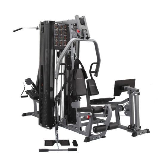
- Page 1 Assembly and Operating Instructions max. 120 kg ~ 60 Min. 33 kg L 108 | B 56 | H 139 SW-95.0205.01.01 Art. No. SW-95.0205 Bodycraft Family X-Press Pro...
-
Page 3: Table Of Contents
Content GENERAL INFORMATION Technical Data Personal Safety Set-Up Place ASSEMBLY General Instructions Scope of Delivery Assembly STORAGE AND TRANSPORT General Instructions TROUBLESHOOTING, CARE AND MAINTENANCE General Instructions Faults and Fault Diagnosis Maintenance and Inspection Calendar DISPOSAL RECOMMENDED ACCESSORIES ORDERING SPARE PARTS Serial Number and Model Name Parts List Exploded Drawing... - Page 5 BodyCraft® weight stations, for example, offer a very wide range of exercise possibilities. This ranges from traditional strength training such as bench presses to rehabilitation exercises and workouts for complex sports such as golf, tennis or badminton.
- Page 6 ABOUT THIS MANUAL Please carefully read the entire manual before installation and first use. The manual will help you to quickly set up the system and explains how to safely use it. Make sure that all persons exercising with the equipment (especially children and persons with physical, sensory, mental or motor disabilities) are informed about this manual and its contents in advance.
-
Page 7: General Information
GENERAL INFORMATION Technical Data Weight and Dimensions Packaging dimensions (L x W x H) and article weight (gross, incl. packaging) approx.: Box 1: 218 cm x 60 cm x 17 cm 75.8 kg Box 2: 134.7 cm x 106.7 cm x 28.6 cm 76.8 kg Box 3: 158.5 cm x 74 cm x 21 cm... -
Page 8: Personal Safety
Personal Safety DANGER ⚠ Before you start using the equipment, you should consult your physician that this type of exercise is suitable for you from a health perspective. Particularly affected are persons who: have a hereditary disposition to high blood pressure or heart disease, are over the age of 45, smoke, have high cholesterol values, are overweight and/or have not exercised regularly in the past year. -
Page 9: Set-Up Place
Set-Up Place WARNING ⚠ Do not place the equipment in main corridors or escape routes. ⚠ CAUTION Choose a location in which to place the equipment such that there is enough free space/ clearance to the front, the rear and to the sides of the equipment. The training room should be well ventilated during training and not be exposed to any draughts. -
Page 10: Assembly
ASSEMBLY General Instructions ⚠ DANGER Do not leave any tools, packaging materials such as foils or small parts lying around, as otherwise there is a danger of suffocation for children. Keep children away from the equipment during assembly. ⚠ WARNING Pay attention to the instructions attached to the equipment in order to reduce the risk of injuries. -
Page 11: Scope Of Delivery
Scope of Delivery The scope of delivery consist of the following parts. At the beginning, check whether all parts and tools belonging to the device are included in the scope of delivery and whether damage has occurred. In the event of complaints, the contractual partner must be contacted directly. CAUTION ⚠... -
Page 16: Assembly
Assembly Before assembly, take a close look at the individual assembly steps shown and carry out the assembly in the order given. NOTICE First loosely screw all parts together and check that they fit properly. Tighten the screws using the tool only when you are instructed to do so. If you have difficulty recognising the graphics, we recommend that you open and/or download the PDF instructions stored in the webshop on your end device (e.g. - Page 18 Step 2: Assembly of the Top Frame and Weight Stacks Assemble the top frame (10) to the front and rear uprights (3 & 4) with four bolts (122) and four nuts (153). Assemble the lat bar holder (11) to the top frame (10) with two bolts (128), four washers (147) and two nuts (154).
- Page 20 Step 3: Assembly of the Seats Part 1 Assemble the front seat frame (18) to the front upright (4) with two bolts (128), four washers (147) and two nuts (154). Assemble the front seat frame (18) to the base frame (1) with one bolt (126), two washers (147) and one nut (154).
- Page 21 18. Moisten two foam pads with foam pad covers (103 & 88) and slide it onto each end of tube (31). 19. Assemble two plastic covers (66) to both foam pads with foam pad covers (103 & 88) and secure the pads with two washers (69) by using two screws (157) and two washers (173). 20.
- Page 22 Step 3: Assembly of the Seats Part 2 Assemble the seat back adjuster (23) to rear upright (3) with one bolt (128) and one nut (154). It may be necessary to tighten this bolt, then loosen just enough to let the seat back adjuster (23) pivot freely.
- Page 24 Step 4: Assembly of the Bench Press and leg Press Attach the press arm selector (12) to top frame (10) by aligning holes and inserting one pivot axle (33). Secure with pre-assembled set screw. Attach the press arm (17) to press arm selector (12) by aligning holes and inserting one pivot axle (33) and one axle (33A).
- Page 26 Step 5: Assembly of the Press Cable NOTICE Assemble cables and pulleys at the same time. Attach the loop end of press cable (109) to the bracket on the front upright (4). Route the cable over and around the left side (perspective from a person on the seat) of the pulley mounted in press arm selector (12).
- Page 28 Step 6: Assembly of the Low Cable NOTICE Do not use this cable if you have purchased the optional hip station. Use the hip station cable instead. Route the low cable (110) under two pulleys (82) on low row base (9) as shown in fig. 1 and 2. Route the cable up over the lower pulley in adjustable pulley block (30) as shown in fig.
- Page 29 Step 7: Assembly of the Ab Crunch Cable Route the ab crunch cable (111) through the (lower) slot and over the pulley in the front upright (4) as shown in fig. 2. Route the cable down and around the pulley mounted on rear of front upright (4), up and over lower pulley in adjustable pulley block (30) as shown in fig.
- Page 30 Step 8: Assembly of the Top Cable Route threaded end of top cable (112) over the pulley mounted to top frame (10) as shown in fig. 1. Route the cable through the slot in rear upright (3), over pulley in top frame (10), under and around top pulley in pulley block (30), up and over pulley mounted on weight stack top (7) and under top pulley in adjustable pulley block (30) as shown in fig.
- Page 31 Step 9: Assembly of the Cable Arm Connecting Cable Hook the cable arm connecting cable (113) on the bracket welded to cable assembly (27). Route the cable up and over low pulley in adjustable pulley block (30) as shown in fig. 2. Screw the threaded cable end into single pulley block (25).
- Page 32 Step 10: Assembly of the Cable Arm Cable Slide the single pulley block (25) onto pulley guide rod (16). Insert the top end of pulley guide rod (16) into the top guide rod holder welded to top frame (10). Push the pulley guide rod (16) as far as possible into the hole. Slide the bottom end of pulley guide rod (16) into guide rod holder welded to base frame (1).
- Page 34 Step 11: Assembly of the Leg Press Cable Screw the threaded end of leg press cable (116) approx. half way into the receiver on base frame (1). Route the cable up and over the lower pulley in adjustable pulley block (30). Route the cable down and under the pulley on the weight stack base (5) as shown in fig.
- Page 36 Step 12: Assembly of the Weight Stack Shrouds and Poster Plates Attach the weight stack shrouds (32) to weight stack bases (5 & 6) and tops (7 & 8) with eight washers (148) and eight bolts (135). NOTICE Make sure to keep all bolts in the frame loose to ensure that holes line up easily. Attach the poster plates (37 &...
-
Page 37: Storage And Transport
STORAGE AND TRANSPORT General Instructions ⚠ WARNING The storage location should be chosen so that improper use by third parties or children can be prevented. If your equipment does not have transportation wheels, the equipment must be disassembled before transportation. ࣑... -
Page 38: Troubleshooting, Care And Maintenance
TROUBLESHOOTING, CARE AND MAINTENANCE General Instructions ⚠ WARNING Do not make any improper changes to the equipment. CAUTION ⚠ Damaged or worn components may affect your safety and the life of the equipment. Therefore, immediately replace damaged or worn components. In such a case, contact the contract partner. -
Page 39: Maintenance And Inspection Calendar
Maintenance and Inspection Calendar To avoid damage from body sweat, the equipment must be cleaned with a damp towel (no solvents!) after each training session. The following routine tasks must be performed at the specified intervals: Part Weekly Monthly Quarterly Cables Screw connections Pulleys and cable routing... -
Page 40: Recommended Accessories
RECOMMENDED ACCESSORIES To make your training experience even more efficient and pleasant, we recommend that you add suiting accessories to your fitness equipment. This could be a floor mat, for example, which makes your fitness equipment stand more securely and also protects the floor from falling sweat, but it could also be additional handrails on some treadmills or silicone spray to keep moving parts in good shape. -
Page 41: Ordering Spare Parts
The serial number of your equipment is unique. It's located on a white sticker. The exact position of this sticker is shown in the following illustration. Enter the serial number in the appropriate field. Serial number: Brand / Category: bodycraft / multi gym Model Name: Family X-Press pro Article Number: SW-95.0205... -
Page 42: Parts List
Parts List Name Qty. BASE FRAME BASE STABILIZER BASE STABILIZER REAR UPRIGHT FRONT UPRIGHT WEIGHT STACK BASE (Leg Press Side) WEIGHT STACK BASE (Low Row Side) WEIGHT STACK TOP (Leg Press Side) WEIGHT STACK TOP (Low Row Side) LOW ROW BASE TOP FRAME LAT BAR HOLDER PRESS ARM SELERTOR... - Page 43 SWIVEL CABLE ARM TOP ADJUSTABLE PULLEY BLOCK 1" CHROME ROLLER TUBE WEIGHT STACK SHROUD 1" PIVOT AXLE 19.95mm AXLE CABLE ARM COLLAR LAT BAR LOW ROW BAR LEFT POSTER PLATE RIGHT POSTER PLATE LEG EXTENSION AXLE 608ZB BEARING STEEL SPACER AXLE COLLAR BEARING BASIN BEARING...
- Page 44 50 X 75mm RECT. PLUG 50mm SQ. PLUG 45mm SQ. PLUG PLASTIC COVER 30 X 60mm RECT. PLUG 25 X 50mm RECT. PLUG PLASTIC WASHER 1/2" ROUND PLUG SPACER PLASTIC GUIDE ROD HOLDER 1" PLASTIC BUSHING 28.6mm STEEL BUSHING 25.4mm STEEL BUSHING 1/2"...
- Page 45 SNAP HOOK LOW ROW CHAIN AB CRUNCH STRAP SINGLE HANDLE ANKLE STRAP FOAM PAD BACK PAD SEAT PAD BACK PAD FOR LEG PRESS SEAT PAD FOR LEG PRESS TRIM FOR WEIGHT SHROUD PRESS CABLE LOW CABLE AB CRUNCH CABLE TOP CABLE CABLE ARM CONNECTING CABLE CABLE ARM CABLE REMOVABLE END CABLE ARM CABLE...
- Page 46 5/16" X 1/2" HEX THREADED BOLT 5/16" X 1-1/2" HEX BOLT 5/16" X 5/8" ROUND BOLT 3/8" X 5/8" ROUND BOLT 3/8" X 1/2" ROUND BOLT 3/8" X 5/8" SET SCREW 5/16" X 1/4" SET SCREW 141A 5/16" X 1/2" SET SCREW TOP PLATE BOLT 8 X 53mm FEMALE BOLT FOR POSTER 6 X 12mm MALE NUT FOR POSTER...
- Page 47 5/8" NYLON NUT 1/2" NYLON NUT 3/8" NYLON NUT 5/16" NYLON NUT 3/8" X 1" INNER HEX SCREW 5/16" X 1-1/4" SUNKEN HEAD SCREW 5/16" NUT 1-1/4" HAND GRIP 1" T SHAPE END PLUG HOOK PLATE COLLAR SEALING RING M6 SET SCREW M5 X 18mm ROUND HEAD SCREW M5 NYLON NUT STEEL TUBE...
-
Page 48: Exploded Drawing
Exploded Drawing... - Page 49 EXPLODED VIEW...
-
Page 50: Warranty
WARRANTY Training equipment from cardiostrong® is subject to strict quality control. However, if a fitness equipment purchased from us does not work perfectly, we take it very seriously and ask you to contact our customer service as indicated. We are happy to help you by phone via our service hotline. Error Descriptions Your fitness equipment is developed for long-term, high-quality training. - Page 51 Warranty Conditions For the warranty to be valid, the following steps must be taken: Please contact our customer service by email or phone. If the product under warranty has to be sent in for repair, the seller bears costs. After expiry of the warranty, the buyer bears the costs of transport and insurance.
-
Page 52: Contact
CONTACT TECHNIK TEKNIK OG SERVICE TECHNIQUE & SERVICE �� �� �� +49 4621 4210-900 80 90 16 50 +33 (0) 172 770033 +49 4621 4210-945 +49 4621 4210-933 �� +49 4621 4210-698 �� �� info@fitshop.dk service-france@fitshop.fr �� technik@sport-tiedje.de �� �� Åbningstider kan findes på... - Page 53 LIVE FITNESS WEBSHOP AND SOCIAL MEDIA Sport-Tiedje is Europe’s largest specialist store www.sport-tiedje.co.uk for home fitness equipment with currently over www.sport-tiedje.de/blog 70 stores and one of the world’s most renowned online mail order companies for fitness equipment. Private customers order via the 25 www.facebook.com/SportTiedje web shops in the respective national language or have their desired equpiment assembled on...
- Page 54 Notes...
- Page 56 Bodycraft Family X-Press Pro...
Need help?
Do you have a question about the Family X-Press Pro and is the answer not in the manual?
Questions and answers