Table of Contents
Advertisement
Quick Links
Advertisement
Table of Contents

Related Manuals for PXM PX292


Summary of Contents for PXM PX292
- Page 1 PX292 PX292-L0 DMX/4-20mA Interface 8ch User manual...
-
Page 2: Table Of Contents
Table of Contents 1 Description....................4 2 Safety conditions..................5 3 Connectors and control elements............6 4 Programming....................7 4.1 Button features......................7 4.2 Information parameters..................... 7 4.3 Setting the DMX address................... 8 4.3.1 Setting the DMX address – L0 version............9 4.4 Characteristics of the output channels..............10 4.4.1 Characteristics of the output channels –... - Page 3 Manufacturer reserves the right to make modifications in order to improve device operation. PXM Marek Żupnik sp.k. Podłęże 654 tel. +48 12 385 83 06 32-003 Podłęże mail: info@pxm.pl Rev.2-0 BDO register number 000005972 www.pxm.pl 04.07.2022...
-
Page 4: Description
Description PX292 is used for processing DMX-512 signal to analog 4 – 20mA. In addition to DMX signal decoding, PX292 allows to program unit reaction to loss of DMX signal. Individually programmable parameters allow for independent definition of a DMX address from the range 1 – 512 for each channel. -
Page 5: Safety Conditions
Safety conditions PX292 is a device powered by low voltage equal to 12 – 24V DC; however, please observe the following safety rules during its installation and use: 1. The device mat be connected to 12 – 24V DC with current-carrying capacity compatible with technical data. -
Page 6: Connectors And Control Elements
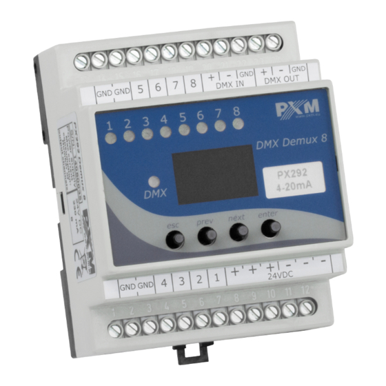
Connectors and control elements DMX input 4 - 20mA control outputs DMX output signaling LEDs display DMX LED control keys 4 - 20mA control outputs power supply 12 - 24V DC... -
Page 7: Programming
– takes to a higher menu level or increase the set values enter – takes to device programming function and confirms the set values 4.2 Information parameters In PX292-L0, the user can display the serial number on the screen of the device. ENTER... -
Page 8: Setting The Dmx Address
4.3 Setting the DMX address The menu of the PX292 device allows to set the DMX address of the device within the range 1 – 505. To set the DMX address as a group: 1. Set the Adr function. 2. Use the next or prev buttons to set the desired DMX address. Press the enter button to confirm. -
Page 9: Setting The Dmx Address - L0 Version
4.3.1 Setting the DMX address – L0 version In the PX292-L0 version, the user can select a DMX address from the range 1 – 512 (when the Cbn operating mode is set to 8ch), it means that if the user selects the address, e.g. 510, then channels 1 – 3 will take successively addresses 510, 511 and 512. -
Page 10: Characteristics Of The Output Channels
To set the DMX address in the L0 version (PX292-L0) Adv operation mode: ENTER ENTER ENTER NEXT NEXT ENTER NEXT NEXT ENTER ENTER NEXT NEXT NOTE! Information whether the device is the L0 version is displayed during device start-up. 4.4 Characteristics of the output channels Available parameters: •... - Page 11 To set characteristics for all channels: 1. From the boot menu, enter the ALL group setting menu. 2. Press enter again to be able to change settings for all channels. 3. Select Cur with the next button, this will allow to change the dimming characteristics of the channels.
-
Page 12: Characteristics Of The Output Channels - Version L0
To set characteristics for all channels: 1. From the start menu, enter the group settings menu Ind. 2. Use the next or prev buttons to select the output channel and click enter. 3. Select Cur with the next button, this will allow to change the dimming characteristics of the channels. -
Page 13: Response To The Loss Of Dmx Signal
Available parameters: Lin – linear characteristic 4 – 20mA, • S_P – switching characteristic (on / off), • uSr – user-defined characteristic, linear, ranging from Min to Max. The • minimum and maximum values can be set in the range from 4 to 20mA. - Page 14 The following options are available: Pr1 – Pr2 – starting program 1 or 2, • on – switching all outputs on 100%, • oFF – complete switch-off of outputs, • HLd – holding the last DMX value, • • Sc1 – Sc4 – scene 1, 2, 3 or 4. Up to 10 steps can be created in the program (F01 –...
- Page 15 Default programs (version L0 ): Steps Pr1 (SPd 01.0 / FAd 050) Pr2 (SPd 01.0 / FAd 050) In each of the four scenes, you can statically program the values of each of the eight output channels separately in the range from 0 to 255. Default scenes (version L0 ): Sc1 –...
- Page 16 To run the function, enter the noS option: 1. From the boot menu, go to the noS settings and press enter. 2. Using the next or prev buttons select the behavior of the fixture on the disappearance of DMX signal. ENTER 2 x NEXT ENTER...
- Page 17 NOTE! In the L0 version of the device, setting the response to the disappearance of the DMX signal is presented below. Information whether the device is the L0 version is displayed during device start-up. ENTER NEXT ENTER ENTER ENTER ENTER NEXT NEXT NEXT...
-
Page 18: Smoothing Function
4.6 Smoothing function The device also has the smoothing option. Smoothing allows for smooth color changes. When this option is enabled, switching between successive DMX values sent to channels is smooth, which prevents abrupt changes in current. In order to start the smoothing function, enter the Sth option: 1. -
Page 19: Operation Mode
ENTER NEXT NEXT 4.7 Operation mode In the PX292-L0 device, the user can change the Cbn operating mode, which only affects the way of setting the DMX address: 8ch – DMX address is set in groups for all channels, •... -
Page 20: Screen Blanking
NOTE! By changing the working mode from Adv to 8ch the DMX addresses will be set sequentially starting from the DMX address of channel 1 set in Adv. ENTER 4 x NEXT ENTER NEXT 4.8 Screen blanking The device has been equipped with the option of switching off backlight of the screen. -
Page 21: Default Settings And Device Errors
In such a case, try to restore the device to its default settings before sending the PX292 / PX292-L0 to the service center. If, after restoring to its default settings, the device still does not operate... -
Page 22: Restore Default Settings
4.9.1 Restore default settings To restore the device to its default settings, press and hold the previous key while switching on the device. One of the messages that will be displayed will say dFl, which means successful restoring to default settings (the previous key has to be held down while powering on the device, until the dFl message is displayed). -
Page 23: Error Message
4.9.2 Error message The device is equipped with a built-in memory work control function. If there are problems with the memory operation on the PX292 display, the Err message appears – memory error. In this situation, select the enter key. The device will reload the default configuration and upload it to the memory. -
Page 24: Mounting
Installation on the mounting rail: 1. Set PX292 diagonally to the rail by hooking the two supports on the rear panel of the unit on the upper part of the assembly strip. -
Page 25: Menu Scheme
Menu scheme ENTER ENTER ENTER NEXT NEXT NEXT ENTER NEXT ENTER ENTER ENTER NEXT NEXT NEXT NEXT ENTER ENTER NEXT ENTER ENTER ENTER NEXT NEXT NEXT NEXT NEXT ENTER NEXT NEXT NEXT NEXT NEXT NEXT NEXT NEXT ENTER NEXT NEXT ENTER NEXT NEXT... -
Page 26: Menu Scheme - L0 Version
Menu scheme – L0 version ENTER ENTER ENTER ENTER NEXT NEXT NEXT NEXT ENTER ENTER ENTER ENTER NEXT NEXT NEXT NEXT NEXT mode NEXT ENTER NEXT NEXT NEXT ENTER ENTER NEXT NEXT NEXT NEXT NEXT NEXT NEXT NEXT ENTER NEXT NEXT ENTER ENTER... -
Page 27: Rdm - Available Parameters
RDM – available parameters The PX292 supports the DMX – RDM protocol. DMX protocol allows only of a one-way data transmission, while its extension the RDM protocol can transmit information in two directions. This makes possible to simultaneously send and receive information, and hence the possibility of monitoring activities of the compatible devices. - Page 28 Parameter name Description additional device description; It is possible to enter an additional DEVICE_LABEL * 0x0082 device description using up to 32 ASCII characters FACTORY_DEFAULTS 0x0090 device default settings PERSONALITY 0x00E0 DMX operational mode PERSONALITY_ description of individual 0x00E1 DESCRIPTION operational modes selecting an option for the Smooth SMOOTH_OFF/1/2/3/4/5 *...
-
Page 29: Device Update
Device update The update is possible using the PX313 USB / RS485 In device – details can be found in the manual for this module. The device update was also presented in detail on our YouTube channel. https://www.youtube.com/watch?v=lSlFGeXVR_k... -
Page 30: Dmx Signal Connecting
PX292 have to be connected to DMX line in serial mode, with no branches on DMX control cable. That means that DMX line, from the signal source, must be connected to DMX IN pins of PX292 and later, directly from DMX OUT pins to the next device in DMX chain. -
Page 31: Connection Scheme
11 Connection scheme... -
Page 32: Dimensions
12 Dimensions... -
Page 33: Technical Data
13 Technical data PX292 type PX292-L0 power supply 12 – 24V DC number of DMX channels RDM protocol yes (from version 2.06) number of output channels output sockets screw terminals outputs load 4 – 20mA / channel power consumption max. 0.5W weight 0.14kg... - Page 34 Podłęże, 24.08.2021 DECLARATION OF CONFORMITY PXM Marek Żupnik spółka komandytowa Podłęże 654, 32-003 Podłęże we declare that our product: Product name: DMX/4-20mA Interface Product code: PX292 PX292-L0 meets the requirements of the following standards, as well as harmonised standards: PN-EN IEC 63000:2019-01...
Need help?
Do you have a question about the PX292 and is the answer not in the manual?
Questions and answers