
Subscribe to Our Youtube Channel
Related Manuals for Black Box SP141A


Summary of Contents for Black Box SP141A
- Page 1 © Copyright 2000. Black Box Corporation. All rights reserved. 1000 Park Drive • Lawrence, PA 15055-1018 • 724-746-5500 • Fax 724-746-0746...
- Page 2 Order toll-free in the U.S.: Call 877-877-BBOX (outside U.S. call 724-746-5500) FREE technical support 24 hours a day, 7 days a week: Call 724-746-5500 or fax 724-746-0746 Mailing address: Black Box Corporation, 1000 Park Drive, Lawrence, PA 15055-1018 Web site: www.blackbox.com • E-mail: info@blackbox.com...
- Page 3 IN-LINE SURGE PROTECTORS TRADEMARKS ARCNET is a registered trademark of ® DATAPOINT CORPORATION. , AT , PS/2 , and AS/400 are registered ® ® ® ® trademarks of International Business Machines Corporation. Centronics is a registered trademark of Centronics ® Corporation.
-
Page 4: Table Of Contents
IN-LINE SURGE PROTECTORS Contents Chapter Page 1.0 Specifications......... 4 2.0 Description..........6 3.0 Installation ..........11 3.1 SP350A-R2, SP351A-R2 ....13 3.2 SP361A-R2........15 3.3 SP501A ..........16 3.4 SP502A ..........17 3.5 SP503A ..........18 3.6 SP504A ..........18 3.7 SP505A, SP506A......19 3.8 SP507A ..........21 3.9 SP508A ..........22 3.10 SP509A-R2........23 3.11 SP510A-R2........24 3.12 SP511A .........25... - Page 5 IN-LINE SURGE PROTECTORS Chapter Page 3.22 SP521A-R2........36 3.23 SP522A-R2........38 3.24 SP523A-R2........40 3.25 SP524A..........41 3.26 SP525A..........43 3.27 SP365A-R2........45 3.28 SP360A..........47 3.29 SP362A..........48 3.30 SP141A..........49 3.31 SP600A-SP611A.......50...
-
Page 6: Specifications
Clamp Voltage SP350A-R2, SP351A-R2, SP501A, SP505A, SP506A, SP512A-R3, SP516A, SP517A, SP518A-R2, SP519A-R2, SP520A: 8 V SP361A-R2, SP507A, SP509A-R2, SP510A-R2, SP141A, SP521A-R2, SP522A-R2, SP523A-R2, SP524A, SP525A, SP600A, SP602A, SP604A, SP606A, SP608A, SP610A: 18 V SP502A, SP503A, SP504A: 30 V SP508A, SP514A, SP601A, SP603A, SP605A,... - Page 7 CHAPTER 1: Specifications — Interface SP350A-R2, SP351A-R2, SP501A: BNC for Thin Ethernet SP361A-R2, SP507A: RS-232, DB9 SP502A, SP503A, SP504A: ARCNET BNC SP505A, SP506A: Standard Ethernet coax BNC SP508A: RS-422, DB15 SP509A-R2: Token Ring with IBM Type B data connectors SP510A-R2: RJ-21 for RS-232 SP511A: RJ-21 for 10BASE-T Ethernet SP512A-R3: RJ-45 with 10BASE-T Ethernet SP513A-R2: RJ-45 all 8 wires protected...
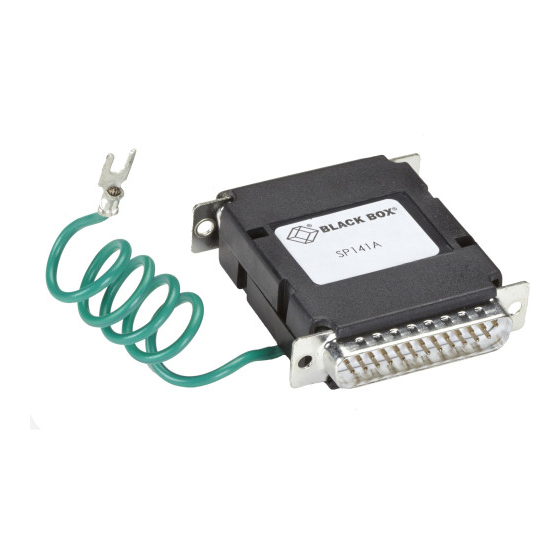
- Page 8 IN-LINE SURGE PROTECTORS SP141A: DB25 4-wire for RS-232, pins: 1(ground) (2, 3, 7, 20) SP600A: 2-wire for RS-232 and Token Ring SP601A—2-wire for RS-422, RS-423, RS-485, and Ethernet SP602A—4-wire for RS-232 and Token Ring SP603A—4-wire for RS-422, RS-423, RS-485, and Ethernet SP604A—6-wire for RS-232 and Token Ring...
-
Page 9: Description
CHAPTER 2: Description 2. Description These in-line surge protectors guard your equipment against induced transient or surge energies caused by nearby AC power lines and cables, close lightning strikes, and electrostatic discharge. The protectors are , which means bipolar they protect your equipment from both positive and negative surges. - Page 10 IN-LINE SURGE PROTECTORS Model No. Name Interface SP506A Thicknet Protector M/F 10BASE5 N-connector SP507A DB15 RS-232 Protector RS-232 ports using DB15 SP508A DB15 RS-422 Protector RS-422, RS-423, and RS-485 ports using DB15 SP509A-R2 Token Ring Protector Token Ring interface using data connector SP510A-R2 25-Pair RS-232 Protector 25-Pair RJ-21-style interface...
- Page 11 (RJ-11 4-wire pigtail into the RJ-45 on the equipment side) SP360A Surge Protector—RS-232 RS-232 ports using DB25 SP362A AUI Surge Protector AUI ports using DB15 SP141A 4-Wire RS-232 Surge RS-232 ports using 4-wire DB25 Protector SP600A 4-Wire Terminal Strip RS-232 and Token Ring...
- Page 12 IN-LINE SURGE PROTECTORS Model No. Name Interface SP602A 4-Wire Terminal Strip RS-232 and Token Ring Protector SP603A 4-Wire Terminal Strip RS-422, RS-423, RS-485, and Protector Ethernet SP604A 6-Wire Terminal Strip RS-232 and Token Ring Protector SP605A 6-Wire Terminal Strip RS-422, RS-423, RS-485, and Protector Ethernet SP606A...
-
Page 13: Installation
CHAPTER 3: Installation 3. Installation Take the following installation precautions: 1. The protector must be installed directly on the communication port of the equipment being protected with no additional connections between the protector and the communication port. Any additional connections or wire length between the protector and the communication port will reduce the effectiveness of the protector. - Page 14 IN-LINE SURGE PROTECTORS 5. Each piece of network equipment being protected must also have an appropriate AC- power surge-suppression device with common mode and normal mode protection. 6. The electrical distribution system of the facility must be properly wired at each and every outlet served by the same branch circuits that supply power to network equipment.
-
Page 15: Sp350A-R2, Sp351A-R2
CHAPTER 3: Installation Follow these steps to install your surge protector: 3.1 SP350A-R2, SP351A-R2 These models protect equipment connected to Thin Ethernet cabling. 1. Disconnect the T connector from the network interface card (NIC). 2. Attach the surge protector to the NIC. 3. - Page 16 CHAPTER 3: IN-LINE SURGE PROTECTORS IN-LINE SURGE PROTECTORS SP350A-R2 SP351-R2 SP502A SP503A "T" Connector Ground Wire Fig. 3-1. Typical Application of the SP350A-R2, SP351A-R2, SP502A, or SP503A.
-
Page 17: Sp361A-R2
CHAPTER 3: Installation 3.2 SP361A-R2 This model protects a PC with a DB9 serial port. 1. Disconnect the cable from the PC’s serial port. 2. Connect the surge protector to the PC’s serial port. 3. Connect the ground wire to the equipment chassis. -
Page 18: Sp501A
IN-LINE SURGE PROTECTORS 3.3 SP501A This model replaces the standard T connector on the network interface card (NIC) to protect the attached workstation from surges. 1. Remove the old T connector. 2. Attach the surge protector to the NIC. 3. Connect the ground wire on the protector to the equipment chassis. -
Page 19: Sp502A
CHAPTER 3: Installation 3.4 SP502A This model attaches to your network interface card (NIC) to protect your equipment from surges. (Refer to Fig. 3-1.) 1. Disconnect the cable attached to the NIC. 2. Attach the surge protector to the NIC. 3. -
Page 20: Sp503A
IN-LINE SURGE PROTECTORS 3.5 SP503A This model attaches to ARCNET network interface cards (NICs). (See Fig. 3-1.) 1. Disconnect the cable from the NIC. 2. Attach the surge protector to the NIC. 3. Attach the ground wire to the equipment’s chassis. -
Page 21: Sp505A, Sp506A
CHAPTER 3: Installation CHAPTER 3: Installation 3.7 SP505A, SP506A These models protect equipment attached to Thick Ethernet. (See Fig. 3-3.) Intrusive taps 1. Remove the terminator. 2. Connect the protector to the end of the segment. 3. Reconnect the terminator and ground the protector to the terminator ground. - Page 22 IN-LINE SURGE PROTECTORS Terminator SP505A Trunk SP506A Cable Transceiver Ground Wire To Ground Wire to Terminator Ground Grounded Terminator (one end only) Terminator SP505A SP506A Trunk Cable Ground Transceiver Wire Fig. 3-3. Typical Application of the SP505A and SP506A. NOTE: For both transceiver types, install an AUI Surge Protector (SP362) between the transceiver and the drop cable.
-
Page 23: Sp507A
CHAPTER 3: Installation 3.8 SP507A This model protects RS-232 interfaces that use a DB15 connection. 1. Unplug the data cable. 2. Plug the protector directly into the equipment. 3. Plug the data cable into the surge protector. NOTE: You must ensure that the equipment chassis is connected to the connector housing. -
Page 24: Sp508A
IN-LINE SURGE PROTECTORS 3.9 SP508A This model protects RS-422 interfaces that use a DB15 connection. 1. Unplug the data cable. 2. Connect the protector directly to the equipment. 3. Connect the data cable to the surge protector. NOTE: You must ensure that the equipment chassis is connected to the connector shell. -
Page 25: Sp509A-R2
CHAPTER 3: Installation 3.10 SP509A-R2 This model protects Multistation Access Unit (MAU) ports from surge damage. (See Fig 3-4.) 1. Unplug the data connector from the MAU. 2. Connect the surge protector to the MAU port. 3. Connect the data cable to the surge protector. -
Page 26: Sp510A-R2
IN-LINE SURGE PROTECTORS 3.11 SP510A-R2 This model protects RS-232 connectors using the RJ-21 50-position plugs. (See Fig. 3-5.) 1. Unplug the existing 50-pin cable. 2. Attach the surge protector directly to your equipment. 3. Connect the chassis ground strap. 4. Connect the cable to the surge protector. NOTE: Use with SP515A individual in-line surge protectors at the peripheral devices. - Page 27 CHAPTER 3: Installation Telco Telco Connector Connector 25 Pair on Block on Block Telco Cable SP510A SP510A Wiring Wiring Async CPU Block Block Ground Wire SP515A SP515A Fig. 3-5. Typical Application of the SP510A-R2.
-
Page 28: Sp511A
IN-LINE SURGE PROTECTORS 3.12 SP511A This model plugs into a concentrator’s RJ-21 50-pin telco connector to protect the concentrator from surges on the data side. 1. Unplug the 50-pin cable. 2. Attach the surge protector to the 50-pin connector on the concentrator. 3. -
Page 29: Sp512A-R3
CHAPTER 3: Installation 3.13 SP512A-R3 This model protects your RJ-45 10BASE-T interface. It also protects RS-422, RS-485, and RS-423 ports. To install, follow these steps: 1. Unplug the existing data cable from the device. 2. Attach the surge protector, and ground it directly to the equipment’s metal chassis. -
Page 30: Sp513A-R2
IN-LINE SURGE PROTECTORS 3.14 SP513A-R2 This model protects your T1 interfaces from dangerous surges. 1. Disconnect the T1 line from the unit. 2. If the unit you wish to protect is metal, plug the surge protector into the unit and attach the ground wire to the chassis of the unit. -
Page 31: Sp514A
CHAPTER 3: Installation 3.15 SP514A This model protects your Token Ring interface. 1. Unplug the data cable from the device. 2. Attach the surge protector to the device. NOTE: For non-PC applications, you may need to install a separate ground wire if chassis ground is not connected to the connector housing on the equipment. -
Page 32: Sp515A-R2, Sp528A
IN-LINE SURGE PROTECTORS 3.16 SP515A-R2, SP528A This model protects your 4-wire RS-232 devices. It also protects Token Ring UTP interfaces. 1. Unplug the RJ-11 4-wire cable from the device you wish to protect. 2. Attach the surge protector to the device, and attach the ground wire to the equipment chassis. -
Page 33: Sp516A
CHAPTER 3: Installation 3.17 SP516A This model protects your Centronics 36-pin interface. 1. Remove the cable from the back of the printer. 2. Connect the surge protector to the Centronics female connector on the printer. 3. Connect the cable to the surge protector. SP516A Printer Centronics... -
Page 34: Sp517A
IN-LINE SURGE PROTECTORS 3.18 SP517A This model protects your CATV interface. 1. Remove the cable from the back of the TV or VCR. 2. Connect the surge protector to the back of the TV or VCR. 3. Connect the CATV coax from your cable company to the surge protector. -
Page 35: Sp518A-R2
CHAPTER 3: Installation 3.19 SP518A-R2 This model protects your AT keyboard port. ® 1. Unplug the keyboard cable from the back of the PC. 2. Plug the surge protector into the PC keyboard port. If you are using a mechanical switch, connect a 5-pin DIN male/male cable between the switch and the protector. -
Page 36: Sp519A-R2
IN-LINE SURGE PROTECTORS 3.20 SP519A-R2 This model protects your PS/2 keyboard port. ® 1. Unplug the keyboard cable from the back of the PC. 2. Plug the surge protector into the PC keyboard port. If you are using a mechanical switch, connect a male/male cable between the protector and the switch. -
Page 37: Sp520A
CHAPTER 3: Installation 3.21 SP520A This model protects your VGA Video Monitor. 1. Unplug the monitor from the video card on your PC. 2. Connect the surge protector to the PC video card. 3. Plug the monitor cable into the surge protector. -
Page 38: Sp521A-R2
IN-LINE SURGE PROTECTORS 3.22 SP521A-R2 This model protects your RJ-45 4-wire UTP Token Ring devices. It also protects RJ-45 4-wire RS-232 equipment. 1. Unplug the data cable. 2. Connect the protector to the device you wish to protect. 3. Connect the protector’s ground wire to the chassis of the device you wish to protect. - Page 39 CHAPTER 3: Installation SP521A Surge Protector Ground Wire PC with Token Ring Card Fig. 3-15. Typical Application of the SP521A-R2.
-
Page 40: Sp522A-R2
IN-LINE SURGE PROTECTORS 3.23 SP522A-R2 This model protects RJ-45 8-wire UTP Token Ring devices. It also protects RJ-45 8-wire RS-232 devices. 1. Disconnect the data cable from the device to which you wish to connect the protector. 2. Plug the RJ-45 male pigtail into the RJ-45 receptacle on the device you wish to protect. - Page 41 CHAPTER 3: Installation SP522A Surge Protector Ground Wire PC with Token Ring or RS-232 Card Fig. 3-16. Typical Application of the SP522A-R2.
-
Page 42: Sp523A-R2
IN-LINE SURGE PROTECTORS 3.24 SP523A-R2 This model protects Token Ring devices. 1. Remove data cable from the device you wish to protect. 2. Attach a short (1 foot or less) piece of cable from the device to the terminal strip on the protector. -
Page 43: Sp524A
CHAPTER 3: Installation 3.25 SP524A This model protects a twinax device for System 3X or AS/400. 1. Disconnect the data cable from the device. 2. Connect the protector to the device. 3. Attach the ground wire to the device chassis if the chassis is metal. - Page 44 IN-LINE SURGE PROTECTORS Twinax Twinax Cable Cable SP524A SP524A SP524A System Printer AS/400 or Display 3X Host Station Fig. 3-17. Typical Application of the SP524A.
-
Page 45: Sp525A
CHAPTER 3: Installation 3.26 SP525A This model protects a twinax device for System 3X or AS/400. 1. Disconnect the data cable from the device. 2. Connect the surge protector to the device directly. If the device has a female connector, then you may connect a short piece of twinax between the device and the protector. - Page 46 IN-LINE SURGE PROTECTORS AS/400 or 3X Host Short Short Twinax Twinax Cable* Cable* Twinax Cable SP525A SP525A System Printer Display SP525A Station *These cables should be 1 foot (0.3 m) long or less. Fig. 3-18. Typical Application of the SP525A.
-
Page 47: Sp365A-R2
CHAPTER 3: Installation 3.27 SP365A-R2 The Surge Protector—Telco uses high-speed solid- state technology in conjunction with overcurrent circuitry, enabling the protectors to function even under a direct power cross. It protects the center two wires on the RJ-11 or RJ-45 device. The Protector meets or exceeds UL specification 497A. - Page 48 IN-LINE SURGE PROTECTORS Wall Machine Plate Phone Line SP365A-R2 Fig. 3-19. Typical Installation of the SP365A-R2.
-
Page 49: Sp360A
CHAPTER 3: Installation 3.28 SP360A The Surge Protector—RS-232 protects your RS-232 interface using a DB25 connector. Follow these steps to install the Protector: 1. Insert it between the data cable and the I/O port of the equipment you wish to protect. 2. -
Page 50: Sp362A
IN-LINE SURGE PROTECTORS 3.29 SP362A The AUI Surge Protector guards your AUI ports using DB15 connectors. Follow these steps to install the protector: 1. Insert the protector in series between the data cable and the AUI port of the equipment you wish to protect. 2. -
Page 51: Sp141A
2. Install a protector at the other end of the cable. CAUTION You must attach the connector shell to earth/chassis ground through a grounded AC power receptacle to assure effective protection. RS-232 Terminal RS-232 Host Fig. 3-21. Typical Application of the SP141A. -
Page 52: Sp600A-Sp611A
IN-LINE SURGE PROTECTORS 3.31 2-, 4-, 6-, 8-, 10-, and 32-Wire Terminal Strip Protectors (SP600A-SP611A) If you have a terminal-strip protector for RS-232 and Token Ring or RS-422, RS-423, RS-485, and Ethernet (part numbers SP600A-SP611A), follow these instructions to install your unit: 1. - Page 53 CHAPTER 3: Installation Hub or Repeater Terminal or Host or Server PC with Fig. 3-22. Typical Application of the SP600A-SP611A. NOTE 2-wire protectors (SP600A, SP601A) have 4-wire terminal strip. Only the center 2 terminals are wired (active).
- Page 54 NOTES...
Need help?
Do you have a question about the SP141A and is the answer not in the manual?
Questions and answers