Table of Contents
Advertisement
Quick Links
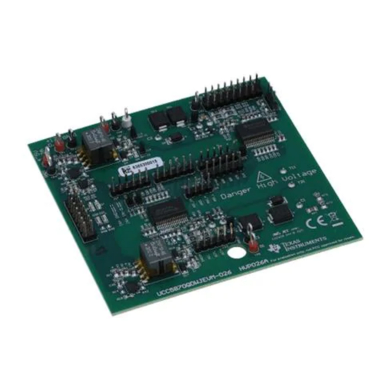
UCC5870QDWJEVM-026 Evaluation Module User's Guide
The evaluation module is designed for evaluation of TI's functional safety compliant 15-A isolated single-
channel gate driver UCC5870-Q1 with advanced protection functions. This EVM is targeted to drive high
power SiC MOSFETs or Si IGBTs in EV/HEV applications. Protection functions such as DESAT short
circuit protection, shunt current sensing support, soft turn-off, VCE overvoltage clamping, UVLO and
OVLO of gate driver power supplies, temperature monitoring and thermal shutdown, and gate monitoring
are included to support system's demanding high reliability. This driver also incorporates sophisticated
diagnostic, protection, and monitoring features through a serial peripheral interface (SPI).
The UCC5870-Q1 evaluation module also includes a MCU daughter board to support SPI communication
and program the UCC5870-Q1, a dedicated GUI is developed for configuring and evaluating UCC5870-
Q1. This evaluation module has pin outputs that support the 820A 750V IGBT module FS820R08A6P2B
connection for high power double pulses test and short circuit test.
1
....................................................................................................................
2
3
4
5
6
...................................................................................................................
7
8
9
1
2
3
4
5
6
GUI First Page
7
8
9
10
11
12
13
14
15
16
17
18
19
20
SLUUC64 - June 2020
Submit Documentation Feedback
.....................................................................................................
................................................................................................................
..................................................................................
...............................................................................................
...........................................................................................................
.............................................................................................................
.................................................................................
..................................................................................................
..............................................................................................................
...............................................................................
........................................................................................................
........................................................................................................
................................................................................
............................................................................................
...................................................................................
..........................................................................................
.........................................................................................
...........................................................................................
Copyright © 2020, Texas Instruments Incorporated
Contents
..........................................................
List of Figures
..........................................................................
...........................................................................
.......................................................................
........................................................
.............................................................................
........................................................................
UCC5870QDWJEVM-026 Evaluation Module User's Guide
User's Guide
SLUUC64 - June 2020
......................................
.............
3
5
6
7
10
23
25
27
31
7
8
8
9
9
10
11
11
12
12
13
13
14
14
15
15
16
16
17
17
1
Advertisement
Table of Contents

Related Manuals for Texas Instruments UCC5870QDWJEVM-026


Summary of Contents for Texas Instruments UCC5870QDWJEVM-026
-
Page 1: Table Of Contents
User's Guide SLUUC64 – June 2020 UCC5870QDWJEVM-026 Evaluation Module User’s Guide The evaluation module is designed for evaluation of TI's functional safety compliant 15-A isolated single- channel gate driver UCC5870-Q1 with advanced protection functions. This EVM is targeted to drive high power SiC MOSFETs or Si IGBTs in EV/HEV applications. - Page 2 PCB Layout Bottom Overlay List of Tables ....................... I/O Description ......................Jumpers Setting ................. UCC5870 EVM Electrical Specifications ......................List of Materials Trademarks UCC5870QDWJEVM-026 Evaluation Module User’s Guide SLUUC64 – June 2020 Submit Documentation Feedback Copyright © 2020, Texas Instruments Incorporated...
-
Page 3: General Ti High Voltage Evaluation User Safety Guidelines
Any other use and/or application are strictly prohibited by Texas Instruments. If you are not suitably qualified, you must immediately stop from further use of the HV EVM. - Page 4 Board must be handled with care by a professional. For safety, use of isolated test equipment with overvoltage and overcurrent protection is highly recommended. UCC5870QDWJEVM-026 Evaluation Module User’s Guide SLUUC64 – June 2020 Submit Documentation Feedback Copyright © 2020, Texas Instruments Incorporated...
-
Page 5: Description
Test pin (use for low voltage test only) Secondary ASC (use for low voltage test only) Test pin (use for low voltage test only) SLUUC64 – June 2020 UCC5870QDWJEVM-026 Evaluation Module User’s Guide Submit Documentation Feedback Copyright © 2020, Texas Instruments Incorporated... -
Page 6: Electrical Specifications
Switching frequency Voltage on C1 and C2 pins for high voltage test (J1, Operating junction temperature range °C 30kHz if ADC is used UCC5870QDWJEVM-026 Evaluation Module User’s Guide SLUUC64 – June 2020 Submit Documentation Feedback Copyright © 2020, Texas Instruments Incorporated... -
Page 7: Test Summary
SPI, daisy chain SPI and address mode SPI. Default setting as in Figure 1 is for regular SPI communication. Figure 1. Default Jumper Settings for EVM MCU Daughter Board (Regular Mode SPI) SLUUC64 – June 2020 UCC5870QDWJEVM-026 Evaluation Module User’s Guide Submit Documentation Feedback Copyright © 2020, Texas Instruments Incorporated... -
Page 8: Jumper Settings For Evm Mcu Daughter Board (Address Mode Spi And Daisy Chain Mode Spi)
13, 14 and 15 is for measuring U4 (UCC5870) Vcc1, Vcc2 and Vee2 quiescent current if current meter can be inserted. Shunt #12 Shunt #15 Shunt #16 Figure 3. Default Jumper Settings for EVM Driver Board UCC5870QDWJEVM-026 Evaluation Module User’s Guide SLUUC64 – June 2020 Submit Documentation Feedback Copyright © 2020, Texas Instruments Incorporated... -
Page 9: Low Voltage Bench Setup Configuration
The test points labels are all on the upside of the J22 due to the space limitation for the bottom side, the measured signal for each pin of J22 is illustrated as in Figure 5 Figure 5. Test Points Labels for J22 SLUUC64 – June 2020 UCC5870QDWJEVM-026 Evaluation Module User’s Guide Submit Documentation Feedback Copyright © 2020, Texas Instruments Incorporated... -
Page 10: Low Voltage Test Procedure Example
Connected’ after few seconds. In case it is not connected, Click ‘Options’ -> ‘Serial port’ and choose the appropriate serial port from the list of available ports. Figure 6. GUI First Page UCC5870QDWJEVM-026 Evaluation Module User’s Guide SLUUC64 – June 2020 Submit Documentation Feedback... -
Page 11: Gui Evm Number And Spi Mode Select
5. Select which driver (high side or low side) to program as in Figure 8 Figure 8. GUI High Side or Low Side Driver Selection SLUUC64 – June 2020 UCC5870QDWJEVM-026 Evaluation Module User’s Guide Submit Documentation Feedback Copyright © 2020, Texas Instruments Incorporated... -
Page 12: Gui Configuration 1
Figure 9. GUI Configuration 1 7. Move to Configuration 2 State in which the registers can be programmed. Figure 10. GUI Configuration 2 UCC5870QDWJEVM-026 Evaluation Module User’s Guide SLUUC64 – June 2020 Submit Documentation Feedback Copyright © 2020, Texas Instruments Incorporated... -
Page 13: Gui Configuration 2 Read All Registers
GUI. In this example, let's disable DESAT protection first. Otherwise Desat fault will trig as there is no IGBT connected Figure 12. GUI Configuration 2 Disable DESAT Protection SLUUC64 – June 2020 UCC5870QDWJEVM-026 Evaluation Module User’s Guide Submit Documentation Feedback Copyright © 2020, Texas Instruments Incorporated... -
Page 14: Gui Configuration 2 Disable Gate Voltage Monitor Function
Figure 13. GUI Configuration 2 Disable Gate Voltage Monitor Function 11. Now move to Active State, setup PWM duty cycle for 50% and PWM frequency for 10kHz Figure 14. GUI Active State Enable Continuous PWM UCC5870QDWJEVM-026 Evaluation Module User’s Guide SLUUC64 – June 2020 Submit Documentation Feedback... -
Page 15: Continuous Pwm Waveforms
13. Stop PWM, click "Test Functions", double pulse test parameters can be set up. Figure 16. GUI Active State Double Pulses Test SLUUC64 – June 2020 UCC5870QDWJEVM-026 Evaluation Module User’s Guide Submit Documentation Feedback Copyright © 2020, Texas Instruments Incorporated... -
Page 16: Double Pulses Test Waveforms
Figure 17. Double Pulses Test Waveforms 15. Next step go back to configuration 2 state and enable the DESAT protection. Figure 18. GUI Configuration 2 Enable DESAT Protection UCC5870QDWJEVM-026 Evaluation Module User’s Guide SLUUC64 – June 2020 Submit Documentation Feedback... -
Page 17: Gui Active Stage Fault Indicator
Desat fault, CH4 is the desat pin voltage, when it reaches about 9.5V, the fault is triggered and nFLT1 pin is pulled low. Figure 20. DESAT Fault Test Waveforms SLUUC64 – June 2020 UCC5870QDWJEVM-026 Evaluation Module User’s Guide Submit Documentation Feedback Copyright © 2020, Texas Instruments Incorporated... -
Page 18: Status Register Shows Desat Fault
ADC fault (Status 5 Register bit[15]) is on with default setting which selects external Vref for ADC but the EVM board doesn't have external Vref, this fault can be cleared by selecting internal Vref. Figure 22. Clear Fault Option UCC5870QDWJEVM-026 Evaluation Module User’s Guide SLUUC64 – June 2020 Submit Documentation Feedback... -
Page 19: Daisy Chain Spi Mode Selection
2. Then for HS GATE in Configuration 1 State, click "Proceed", at this moment, the driver will not move to configuration 2 stage. Figure 24. Daisy Chain SPI Mode High Side CF1 State SLUUC64 – June 2020 UCC5870QDWJEVM-026 Evaluation Module User’s Guide Submit Documentation Feedback Copyright © 2020, Texas Instruments Incorporated... -
Page 20: Daisy Chain Spi Mode Low Side Cf1 State
GUI page of the above step when both high side and low side driver are in configuration 2 state. Figure 26. Daisy Chain SPI Mode High Side and Low Side CF2 State UCC5870QDWJEVM-026 Evaluation Module User’s Guide SLUUC64 – June 2020 Submit Documentation Feedback... -
Page 21: Address Spi Mode Selection
2 state. Figure 28. Address SPI Mode High Side CF1 State: Writing Address 0x01 SLUUC64 – June 2020 UCC5870QDWJEVM-026 Evaluation Module User’s Guide Submit Documentation Feedback Copyright © 2020, Texas Instruments Incorporated... -
Page 22: Address Spi Mode High Side Cf2 State
4. Repeat the same step for the low side driver, chip address 0x02 will be written to the low side driver. Figure 30. Address SPI Mode Low Side CF1 State: Writing Address 0x02 UCC5870QDWJEVM-026 Evaluation Module User’s Guide SLUUC64 – June 2020 Submit Documentation Feedback Copyright ©... -
Page 23: High Voltage Test Example
Driver secondary for low side IGBT Primary side of the driver Driver secondary for high side IGBT Figure 31. EVM Primary and Secondary SLUUC64 – June 2020 UCC5870QDWJEVM-026 Evaluation Module User’s Guide Submit Documentation Feedback Copyright © 2020, Texas Instruments Incorporated... -
Page 24: Evm Connected With Igbt Module
Figure 33 shows an example double test waveform at for 400V, 100A switching. Figure 33. Double Pulses Test Waveforms at 400V 100A UCC5870QDWJEVM-026 Evaluation Module User’s Guide SLUUC64 – June 2020 Submit Documentation Feedback Copyright © 2020, Texas Instruments Incorporated... -
Page 25: Schematic
Schematic Figure 34 Figure 35 show the schematic diagram for the UCC5870 EVM. Figure 34. UCC5870 EVM Low Side Driver Schematic SLUUC64 – June 2020 UCC5870QDWJEVM-026 Evaluation Module User’s Guide Submit Documentation Feedback Copyright © 2020, Texas Instruments Incorporated... -
Page 26: Ucc5870 Evm High Side Driver Schematic
Schematic www.ti.com Figure 35. UCC5870 EVM High Side Driver Schematic UCC5870QDWJEVM-026 Evaluation Module User’s Guide SLUUC64 – June 2020 Submit Documentation Feedback Copyright © 2020, Texas Instruments Incorporated... -
Page 27: Layout Diagrams
Figure 43 show the PCB layout information for the UCC5870 EVM. Figure 36. PCB Layout Top Overlay Figure 37. PCB Layout Top Layer SLUUC64 – June 2020 UCC5870QDWJEVM-026 Evaluation Module User’s Guide Submit Documentation Feedback Copyright © 2020, Texas Instruments Incorporated... -
Page 28: Pcb Layout Inter Layer 1
Layout Diagrams www.ti.com Figure 38. PCB Layout Inter Layer 1 Figure 39. PCB Layout Inter Layer 2 UCC5870QDWJEVM-026 Evaluation Module User’s Guide SLUUC64 – June 2020 Submit Documentation Feedback Copyright © 2020, Texas Instruments Incorporated... -
Page 29: Pcb Layout Inter Layer 3
Layout Diagrams www.ti.com Figure 40. PCB Layout Inter Layer 3 Figure 41. PCB Layout Inter Layer 4 SLUUC64 – June 2020 UCC5870QDWJEVM-026 Evaluation Module User’s Guide Submit Documentation Feedback Copyright © 2020, Texas Instruments Incorporated... -
Page 30: Pcb Layout Bottom Layer
Layout Diagrams www.ti.com Figure 42. PCB Layout Bottom Layer Figure 43. PCB Layout Bottom Overlay UCC5870QDWJEVM-026 Evaluation Module User’s Guide SLUUC64 – June 2020 Submit Documentation Feedback Copyright © 2020, Texas Instruments Incorporated... -
Page 31: Bill Of Materials
J7, J8 Sullins Header, 100mil, 8x2, Gold, TH Connector PBC08DAAN Solutions Sullins J10, J11 Header, 50mil, 3x1, Gold, TH Connector GRPB031VWVN-RC Solutions SLUUC64 – June 2020 UCC5870QDWJEVM-026 Evaluation Module User’s Guide Submit Documentation Feedback Copyright © 2020, Texas Instruments Incorporated... - Page 32 Test Point, Multipurpose, White, TH Keystone 5012 LM25180-Q1 42-VIN PSR Flyback DC/DC Converter Texas U1, U6 With 65-V, 1.5-A Integrated MOSFET, NGU0008C LM25180QNGURQ1 Instruments (WSON-8) UCC5870QDWJEVM-026 Evaluation Module User’s Guide SLUUC64 – June 2020 Submit Documentation Feedback Copyright © 2020, Texas Instruments Incorporated...
- Page 33 RES, 0, 5%, 0.1 W, AEC-Q200 Grade 0, 0603 Vishay-Dale CRCW06030000Z0EA RES, 3.90 k, 0.1%, 0.1 W, 0603 Susumu Co Ltd RG1608P-392-B-T5 SLUUC64 – June 2020 UCC5870QDWJEVM-026 Evaluation Module User’s Guide Submit Documentation Feedback Copyright © 2020, Texas Instruments Incorporated...
- Page 34 TI products. TI’s provision of these resources does not expand or otherwise alter TI’s applicable warranties or warranty disclaimers for TI products. Mailing Address: Texas Instruments, Post Office Box 655303, Dallas, Texas 75265 Copyright © 2020, Texas Instruments Incorporated...
Need help?
Do you have a question about the UCC5870QDWJEVM-026 and is the answer not in the manual?
Questions and answers