Advertisement
www.ti.com
EVM User's Guide: UCC57108EVM
UCC57108 Evaluation Module
Description
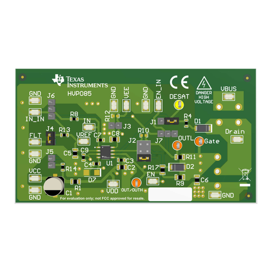
The UCC57108EVM is designed to primarily evaluate
the UCC57108 functionality. The performance of the
driver can be evaluated for capacitive loads or power
devices with TO-220 footprints. The UCC57108EVM
evaluation boards allow for connection to various
test points, such as IN, FLT, DESAT, and VREF, via
surface-mount test points. The UCC57108EVM can
also support different UCC57108 IC variants with the
use of jumpers.
SLUUCX0 – FEBRUARY 2024
Submit Document Feedback
Features
•
Test points allow probing all the key pins of the
UCC57108
•
Allows quick verification of most of the data sheet
parameters
•
Uses jumpers to allow compatibility across all
UCC57108 variants
•
External TO-220 power device low-side connection
•
PCB layout optimized for bias supply bypassing
cap, gate-drive resistance selection
UCC57108 Evaluation Module
Copyright © 2024 Texas Instruments Incorporated
Description
UCC57108 Evaluation Module
1
Advertisement
Table of Contents

Related Manuals for Texas Instruments UCC57108EVM


Summary of Contents for Texas Instruments UCC57108EVM
- Page 1 Description EVM User's Guide: UCC57108EVM UCC57108 Evaluation Module Description Features The UCC57108EVM is designed to primarily evaluate • Test points allow probing all the key pins of the the UCC57108 functionality. The performance of the UCC57108 driver can be evaluated for capacitive loads or power •...
-
Page 2: Kit Contents
(DESAT), and fault signal output. The UCC57108 has low propagation delay and fast rise and fall time. The UCC57108 inputs can tolerate signals as high as 30V regardless of the VDD voltage which enhances device robustness. The UCC57108EVM board can be used to evaluate other pin-to-pin compatible parts in the supported packages. -
Page 3: Jumper Description
Input and Output Characteristics Input V Input V Input current System Characteristics Switching frequency The UCC57108EVM also supports the UCC57102 IC. In this case, the minimum input V is 12.5V. 2.2 I/O Description Table 2-2. UCC57108EVM I/O Description Pins Description positive supply test point. - Page 4 UCC57108C, which has split output, and the UCC57108W, which has enable function. The UCC57108EVM also supports the UCC57102 IC, which is the 12.5V UVLO version of the UCC57108 IC. The UCC57102 has the same variant types as the UCC57108, and the information in this section applies to the UCC57102 IC as well.
- Page 5 Hardware 2.5 DESAT Setup The UCC57108EVM out-the-box evaluates the DESAT protection feature of the UCC57108 when the device is on. This is done with jumper J1 connecting the DESAT pin to the FET drain out-the-box. Because the EVM does not come with a FET, the DESAT input detects open voltage. This triggers the desaturation protection of the device when the user turns the device on and inputs a signal, which ultimately pulls the fault output signal low.
-
Page 6: Equipment Setup
Implementation Results www.ti.com 3 Implementation Results 3.1 Out-The-Box Evaluation This evaluation is to test the UCC57108EVM functionality out the box. The assumption is that the user did not make any adjustments to the board. 3.2 Equipment Setup 3.2.1 Power Supply •... - Page 7 3. Once testing is satisfied, power down the EVM by following the order: a. Turn off function generator. b. Turn off power supply #1. c. Disconnect cables and probes. SLUUCX0 – FEBRUARY 2024 UCC57108 Evaluation Module Submit Document Feedback Copyright © 2024 Texas Instruments Incorporated...
- Page 8 Implementation Results www.ti.com Figure 3-2. Reference waveforms for UCC57108EVM out-of-box evaluation. Note To learn more about why the Out-The-Box Evaluation causes this behavior to occur, see Section 2.5. UCC57108 Evaluation Module SLUUCX0 – FEBRUARY 2024 Submit Document Feedback Copyright © 2024 Texas Instruments Incorporated...
- Page 9 Typical Performance Waveforms 4 Typical Performance Waveforms 4.1 DESAT Feature Figure 4-1. DESAT Feature of the UCC57108 SLUUCX0 – FEBRUARY 2024 UCC57108 Evaluation Module Submit Document Feedback Copyright © 2024 Texas Instruments Incorporated...
- Page 10 Typical Performance Waveforms www.ti.com 4.2 Bipolar Feature of UCC57108B Figure 4-2. Bipolar-Voltage with UCC57108B Installed UCC57108 Evaluation Module SLUUCX0 – FEBRUARY 2024 Submit Document Feedback Copyright © 2024 Texas Instruments Incorporated...
- Page 11 Hardware Design Files 5 Hardware Design Files 5.1 Schematics Figure 5-1 shows the UCC57108EVM schematic diagram. Figure 5-1. UCC57108EVM Schematic SLUUCX0 – FEBRUARY 2024 UCC57108 Evaluation Module Submit Document Feedback Copyright © 2024 Texas Instruments Incorporated...
- Page 12 Hardware Design Files www.ti.com 5.2 PCB Layouts Figure 5-2 through Figure 5-5 show the PCB layout information for the UCC57108EVM. Figure 5-2. Top Overlay Figure 5-3. Top Layer UCC57108 Evaluation Module SLUUCX0 – FEBRUARY 2024 Submit Document Feedback Copyright © 2024 Texas Instruments Incorporated...
- Page 13 Hardware Design Files Figure 5-4. Bottom Overlay Figure 5-5. Bottom Layer SLUUCX0 – FEBRUARY 2024 UCC57108 Evaluation Module Submit Document Feedback Copyright © 2024 Texas Instruments Incorporated...
-
Page 14: Bill Of Materials
TP9, TP11, TP12 Test Point, Multipurpose, Orange, TH High-Speed, Low-Side Gate Driver With DESAT Protection 6 Compliance Information The UCC57108EVM is in compliance with RoHS and REACH. 7 Additional Information 7.1 Trademarks All trademarks are the property of their respective owners. - Page 15 STANDARD TERMS FOR EVALUATION MODULES Delivery: TI delivers TI evaluation boards, kits, or modules, including any accompanying demonstration software, components, and/or documentation which may be provided together or separately (collectively, an “EVM” or “EVMs”) to the User (“User”) in accordance with the terms set forth herein.
- Page 16 www.ti.com Regulatory Notices: 3.1 United States 3.1.1 Notice applicable to EVMs not FCC-Approved: FCC NOTICE: This kit is designed to allow product developers to evaluate electronic components, circuitry, or software associated with the kit to determine whether to incorporate such items in a finished product and software developers to write software applications for use with the end product.
- Page 17 www.ti.com Concernant les EVMs avec antennes détachables Conformément à la réglementation d'Industrie Canada, le présent émetteur radio peut fonctionner avec une antenne d'un type et d'un gain maximal (ou inférieur) approuvé pour l'émetteur par Industrie Canada. Dans le but de réduire les risques de brouillage radioélectrique à...
- Page 18 www.ti.com EVM Use Restrictions and Warnings: 4.1 EVMS ARE NOT FOR USE IN FUNCTIONAL SAFETY AND/OR SAFETY CRITICAL EVALUATIONS, INCLUDING BUT NOT LIMITED TO EVALUATIONS OF LIFE SUPPORT APPLICATIONS. 4.2 User must read and apply the user guide and other available documentation provided by TI regarding the EVM prior to handling or using the EVM, including without limitation any warning or restriction notices.
- Page 19 Notwithstanding the foregoing, any judgment may be enforced in any United States or foreign court, and TI may seek injunctive relief in any United States or foreign court. Mailing Address: Texas Instruments, Post Office Box 655303, Dallas, Texas 75265 Copyright © 2023, Texas Instruments Incorporated...
- Page 20 TI products. TI’s provision of these resources does not expand or otherwise alter TI’s applicable warranties or warranty disclaimers for TI products. TI objects to and rejects any additional or different terms you may have proposed. IMPORTANT NOTICE Mailing Address: Texas Instruments, Post Office Box 655303, Dallas, Texas 75265 Copyright © 2024, Texas Instruments Incorporated...
Need help?
Do you have a question about the UCC57108EVM and is the answer not in the manual?
Questions and answers