
Related Manuals for Texas Instruments UCC29950EVM-631


Summary of Contents for Texas Instruments UCC29950EVM-631
- Page 1 Using the UCC29950EVM-631 User's Guide Literature Number: SLUUB69A March 2015 – Revised March 2015...
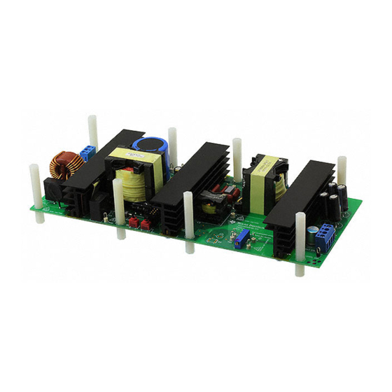
- Page 2 300-W PFC/LLC Off-Line PSU Module Introduction The UCC29950EVM-631 evaluation module is a 300-W nominal, two-stage off-line converter. The EVM consists of a Continuous Conduction Mode (CCM) PFC input stage followed by a half-bridge LLC output and isolation stage. It provides a 12-V constant-voltage output with overload and short circuit protection.
-
Page 3: Typical Applications
80+ SILVER PC Silver Box • Gaming • Audio • Lighting Drivers • Industrial Power SLUUB69A – March 2015 – Revised March 2015 Using the UCC29950EVM-631 300-W PFC/LLC Off-Line PSU Module Submit Documentation Feedback Copyright © 2015, Texas Instruments Incorporated... -
Page 4: Electrical Performance Specifications
LINE OUT(max) Steady-state output over current threshold ≤ V ≤ V IN(min) IN(max) Using the UCC29950EVM-631 300-W PFC/LLC Off-Line PSU Module SLUUB69A – March 2015 – Revised March 2015 Submit Documentation Feedback Copyright © 2015, Texas Instruments Incorporated... - Page 5 η Average efficiency = 230 V = 50 Hz, 90.2% LINE OUT(max) Ambient temperature °C SLUUB69A – March 2015 – Revised March 2015 Using the UCC29950EVM-631 300-W PFC/LLC Off-Line PSU Module Submit Documentation Feedback Copyright © 2015, Texas Instruments Incorporated...
- Page 6 Schematic www.ti.com Schematic Figure 1. UCC29950EVM-631 Schematic - Control Using the UCC29950EVM-631 300-W PFC/LLC Off-Line PSU Module SLUUB69A – March 2015 – Revised March 2015 Submit Documentation Feedback Copyright © 2015, Texas Instruments Incorporated...
- Page 7 Schematic www.ti.com Figure 2. UCC29950EVM-631 Schematic - Power SLUUB69A – March 2015 – Revised March 2015 Using the UCC29950EVM-631 300-W PFC/LLC Off-Line PSU Module Submit Documentation Feedback Copyright © 2015, Texas Instruments Incorporated...
-
Page 8: Test Setup
Test Setup www.ti.com Test Setup Figure 3 shows the test setup recommended in order to evaluate the UCC29950EVM-631 in Self Bias Mode. Figure 4 shows the test setup recommended in order to evaluate the UCC29950EVM-631 in Aux Bias Mode. The 62-k: resistor and the... - Page 9 J2 as shown or at TP31 (pos) and TP 32 (neg) Figure 4. UCC29950EVM-631 Recommended Aux Bias Test Set Up WARNING High voltages that may cause injury exist on this evaluation module (EVM). Please ensure all safety procedures are followed when working on this EVM.
-
Page 10: Test Equipment
Fan: A fan, capable of 200 LFM to 400 LFM, should be used to maintain component temperatures within safe operating ranges at all times during operation of the UCC29950EVM-631. Position the fan so as to blow along the length of the heatsink as shown in... -
Page 11: List Of Test Points
PFC stage output voltage (typical 385 V) TP32 PGND Power ground TP33 PGND Power ground SLUUB69A – March 2015 – Revised March 2015 Using the UCC29950EVM-631 300-W PFC/LLC Off-Line PSU Module Submit Documentation Feedback Copyright © 2015, Texas Instruments Incorporated... - Page 12 (i) Verify that the output of the module is within regulation. Startup time may be several seconds. RTN BIAS + Figure 5. J4 Link Setting for Self Bias Mode Using the UCC29950EVM-631 300-W PFC/LLC Off-Line PSU Module SLUUB69A – March 2015 – Revised March 2015 Submit Documentation Feedback...
- Page 13 Figure 8. S1 and S2 Settings for PFC Stage On, LLC Stage Off (Aux Bias Mode only) SLUUB69A – March 2015 – Revised March 2015 Using the UCC29950EVM-631 300-W PFC/LLC Off-Line PSU Module Submit Documentation Feedback Copyright © 2015, Texas Instruments Incorporated...
-
Page 14: Equipment Shutdown
Aux Bias Mode. Never leave a powered EVM unattended for any length of time. Also, the unit should never be handled while power is applied to it. The UCC29950EVM-631 is set at the factory to operate in Aux Bias Mode, with an external bias supply as shown in Figure 4. -
Page 15: Power Factor
Q4 is turned off and the EVM starts. The action of turning Q4 off eliminates the losses in the startup circuit and this helps to reduce the no-load power dissipation of the system. SLUUB69A – March 2015 – Revised March 2015 Using the UCC29950EVM-631 300-W PFC/LLC Off-Line PSU Module Submit Documentation Feedback Copyright © 2015, Texas Instruments Incorporated... -
Page 16: Short Circuit Protection
The operating point for both these features is set at a level which is higher than the point at which the LLC OCP protections operate so they are not normally triggered. Using the UCC29950EVM-631 300-W PFC/LLC Off-Line PSU Module SLUUB69A – March 2015 – Revised March 2015 Submit Documentation Feedback Copyright ©... -
Page 17: Output Voltage Ripple
+VOUT and RTN terminals of J3. The loop area between the scope probe tip and ground should be minimized for accurate ripple and noise measurements. SLUUB69A – March 2015 – Revised March 2015 Using the UCC29950EVM-631 300-W PFC/LLC Off-Line PSU Module Submit Documentation Feedback Copyright © 2015, Texas Instruments Incorporated... -
Page 18: Performance Data And Typical Characteristic Curves
-140 -180 -180 1000 10000 Frequency (Hz) D001 D008 D002 Figure 11. Gain/Phase vs. Frequency Using the UCC29950EVM-631 300-W PFC/LLC Off-Line PSU Module SLUUB69A – March 2015 – Revised March 2015 Submit Documentation Feedback Copyright © 2015, Texas Instruments Incorporated... - Page 19 (as a function of line voltage and current) Efficiency (as a function of line voltage and current) The UCC29950EVM-631 also meets the requirements of 80PLUS Silver with good margin and is close to meeting the requirements of 80PLUS Gold. Table 3. UCC29950EVM-631, Typical Average Efficiency...
-
Page 20: Total Harmonic Distortion
IEC61000-3-2 Class D max Figure 15. UCC29950EVM-631 Current Harmonics (230-V , 50-Hz input, full load) Using the UCC29950EVM-631 300-W PFC/LLC Off-Line PSU Module SLUUB69A – March 2015 – Revised March 2015 Submit Documentation Feedback Copyright © 2015, Texas Instruments Incorporated... -
Page 21: Line/Load Regulation
230 V 115 V 0.95 Input Power (W) D001 Figure 18. Power Factor vs Input Power SLUUB69A – March 2015 – Revised March 2015 Using the UCC29950EVM-631 300-W PFC/LLC Off-Line PSU Module Submit Documentation Feedback Copyright © 2015, Texas Instruments Incorporated... -
Page 22: Input Current
, 60-Hz, full load 2 A/div.) Figure 21. UCC29950EVM-631 Input Current (230-V , 50-Hz, full load 1 A/div.) Using the UCC29950EVM-631 300-W PFC/LLC Off-Line PSU Module SLUUB69A – March 2015 – Revised March 2015 Submit Documentation Feedback Copyright © 2015, Texas Instruments Incorporated... - Page 23 Figure 25. UCC29950EVM-631 Output Noise (115-V , 60-Hz input, full load) (230-V , 50-Hz input, full load) SLUUB69A – March 2015 – Revised March 2015 Using the UCC29950EVM-631 300-W PFC/LLC Off-Line PSU Module Submit Documentation Feedback Copyright © 2015, Texas Instruments Incorporated...
- Page 24 , No Load, Self Bias, Burst Interval is 4-s ms, ΔV is 400 mV intervals, ΔV = 1.5 V Using the UCC29950EVM-631 300-W PFC/LLC Off-Line PSU Module SLUUB69A – March 2015 – Revised March 2015 Submit Documentation Feedback Copyright © 2015, Texas Instruments Incorporated...
- Page 25 Approximately 340 ms Figure 30. V 25 A, Aux Bias Figure 31. V 25 A, Aux Bias SLUUB69A – March 2015 – Revised March 2015 Using the UCC29950EVM-631 300-W PFC/LLC Off-Line PSU Module Submit Documentation Feedback Copyright © 2015, Texas Instruments Incorporated...
-
Page 26: Bias Mode
160 mW + 130 mW = 290 mW 264 V Aux Bias 130 mW 175 mW + 130 mW = 305 mW Using the UCC29950EVM-631 300-W PFC/LLC Off-Line PSU Module SLUUB69A – March 2015 – Revised March 2015 Submit Documentation Feedback Copyright © 2015, Texas Instruments Incorporated... -
Page 27: Evm Assembly Drawing And Pcb Layout
Figure 34 through Figure 37 show the design of the UCC29950EVM-631 printed circuit board. Figure 34. UCC29950EVM-631 Top Layer Assembly Drawing (top view) Figure 35. UCC29950EVM-631 Bottom Layer Assembly Drawing (bottom view) SLUUB69A – March 2015 – Revised March 2015... - Page 28 Figure 36. UCC29950EVM-631 Top Copper (top view) Figure 37. UCC29950EVM-631 Bottom Copper (bottom view) Using the UCC29950EVM-631 300-W PFC/LLC Off-Line PSU Module SLUUB69A – March 2015 – Revised March 2015 Submit Documentation Feedback Copyright © 2015, Texas Instruments Incorporated...
- Page 29 EVM Assembly Drawing and PCB Layout www.ti.com Figure 38. Components Assembly SLUUB69A – March 2015 – Revised March 2015 Using the UCC29950EVM-631 300-W PFC/LLC Off-Line PSU Module Submit Documentation Feedback Copyright © 2015, Texas Instruments Incorporated...
-
Page 30: List Of Materials
List of Materials www.ti.com List of Materials Table 5 lists the UCC29950EVM-631 components according to the schematic shown in Figure 1 Figure Table 5. UCC29950EVM-631 List of Materials REF DES DESCRIPTION PART NUMBER C1, C2 Capacitor, film, 0.47 µF, 275 V, ±20%, TH... - Page 31 CRCW20101R00JNEF Stackpole R4, R5, R6 Resistor, 0.1 Ω, 1%, 2 W, 2512 CSRN2512FTR100 Electronics Inc SLUUB69A – March 2015 – Revised March 2015 Using the UCC29950EVM-631 300-W PFC/LLC Off-Line PSU Module Submit Documentation Feedback Copyright © 2015, Texas Instruments Incorporated...
- Page 32 LLC transformer, 280 µH, TH Renco Electronics RLTI-1115 TP1, TP4 Test point, multipurpose, yellow, TH Keystone 5014 Using the UCC29950EVM-631 300-W PFC/LLC Off-Line PSU Module SLUUB69A – March 2015 – Revised March 2015 Submit Documentation Feedback Copyright © 2015, Texas Instruments Incorporated...
-
Page 33: Revision History
Revision History www.ti.com Table 5. UCC29950EVM-631 List of Materials (continued) REF DES DESCRIPTION PART NUMBER TP2, TP3, TP5, TP6, TP7, TP11, TP12, TP13, TP14, TP15, TP16, TP17, TP18, Test point, multipurpose, white, TH Keystone 5012 TP20, TP21, TP22, TP23, TP24, TP25,... - Page 34 STANDARD TERMS AND CONDITIONS FOR EVALUATION MODULES Delivery: TI delivers TI evaluation boards, kits, or modules, including any accompanying demonstration software, components, or documentation (collectively, an “EVM” or “EVMs”) to the User (“User”) in accordance with the terms and conditions set forth herein. Acceptance of the EVM is expressly subject to the following terms and conditions.
- Page 35 FCC Interference Statement for Class B EVM devices NOTE: This equipment has been tested and found to comply with the limits for a Class B digital device, pursuant to part 15 of the FCC Rules. These limits are designed to provide reasonable protection against harmful interference in a residential installation.
- Page 36 【無線電波を送信する製品の開発キットをお使いになる際の注意事項】 開発キットの中には技術基準適合証明を受けて いないものがあります。 技術適合証明を受けていないもののご使用に際しては、電波法遵守のため、以下のいずれかの 措置を取っていただく必要がありますのでご注意ください。 1. 電波法施行規則第6条第1項第1号に基づく平成18年3月28日総務省告示第173号で定められた電波暗室等の試験設備でご使用 いただく。 2. 実験局の免許を取得後ご使用いただく。 3. 技術基準適合証明を取得後ご使用いただく。 なお、本製品は、上記の「ご使用にあたっての注意」を譲渡先、移転先に通知しない限り、譲渡、移転できないものとします。 上記を遵守頂けない場合は、電波法の罰則が適用される可能性があることをご留意ください。 日本テキサス・イ ンスツルメンツ株式会社 東京都新宿区西新宿6丁目24番1号 西新宿三井ビル 3.3.3 Notice for EVMs for Power Line Communication: Please see http://www.tij.co.jp/lsds/ti_ja/general/eStore/notice_02.page 電力線搬送波通信についての開発キットをお使いになる際の注意事項については、次のところをご覧くださ い。http://www.tij.co.jp/lsds/ti_ja/general/eStore/notice_02.page SPACER EVM Use Restrictions and Warnings: 4.1 EVMS ARE NOT FOR USE IN FUNCTIONAL SAFETY AND/OR SAFETY CRITICAL EVALUATIONS, INCLUDING BUT NOT LIMITED TO EVALUATIONS OF LIFE SUPPORT APPLICATIONS.
- Page 37 Notwithstanding the foregoing, any judgment may be enforced in any United States or foreign court, and TI may seek injunctive relief in any United States or foreign court. Mailing Address: Texas Instruments, Post Office Box 655303, Dallas, Texas 75265 Copyright © 2015, Texas Instruments Incorporated...
-
Page 38: Important Notice
IMPORTANT NOTICE Texas Instruments Incorporated and its subsidiaries (TI) reserve the right to make corrections, enhancements, improvements and other changes to its semiconductor products and services per JESD46, latest issue, and to discontinue any product or service per JESD48, latest issue.
Need help?
Do you have a question about the UCC29950EVM-631 and is the answer not in the manual?
Questions and answers