Advertisement
Quick Links
www.ti.com
EVM User's Guide: UCC27332Q1EVM
UCC27332-Q1 Evaluation Module
Description
The UCC27332Q1EVM is designed to provide an
easy to use tool to evaluate the UCC27332-Q1
performance. The UCC27332-Q1 is a 20-V, single
channel low-side driver with 9-A peak source and
9-A peak sink current for driving Si/IGBTs and GaN
FETs. The UCC27332Q1EVM board can be used
to evaluate other pin-to-pin compatible parts in the
3x3mm MSOP package.
Get Started
1. Order the EVM on ti.com.
2. Review the user's guide.
3. Download the comprehensive reference design
files from the
product
4. See the latest data sheet (SLUSEW3).
SLUUCT5 – OCTOBER 2023
Submit Document Feedback
folder.
Copyright © 2023 Texas Instruments Incorporated
Features
•
EVM for the low-voltage features of the
UCC27332-Q1 gate driver.
•
4.5-V to 18-V VCC power supply range.
•
9-A source, 9-A sink current.
•
-5V input voltage capability on IN input pin.
•
TTL-compatible inputs.
•
PCB layout optimized for bias supply bypassing
capacitors placement, gate-drive resistance
network selection.
•
Evaluate capacitive load, external gate drive
resistor network.
•
Available in 3 mm x 3 mm MSOP8 package.
•
Test points allow probing all the key pins of the
UCC27332-Q1.
Applications
•
Automotive DC-DC converters
•
Automotive on-board charger
•
Telecom DC-DC converters
•
Power factor correction (PFC) circuits
Description
UCC27332-Q1 Evaluation Module
1
Advertisement

Related Manuals for Texas Instruments UCC27332Q1EVM


Summary of Contents for Texas Instruments UCC27332Q1EVM
- Page 1 Description EVM User's Guide: UCC27332Q1EVM UCC27332-Q1 Evaluation Module Description Features The UCC27332Q1EVM is designed to provide an • EVM for the low-voltage features of the easy to use tool to evaluate the UCC27332-Q1 UCC27332-Q1 gate driver. performance. The UCC27332-Q1 is a 20-V, single •...
-
Page 2: Kit Contents
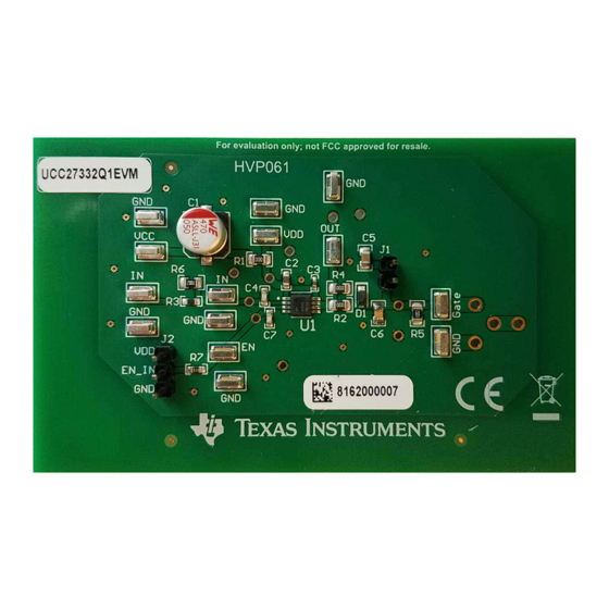
1.1 Introduction The UCC27332Q1EVM is designed to primarily evaluate the UCC27332-Q1 performance. The UCC27332Q1EVM board can be used to evaluate other pin-to-pin compatible parts in the 3x3mm MSOP package. This user's guide describes the characteristics, operation, and use of the UCC27332-Q1 Evaluation Module (EVM). - Page 3 Hardware 2 Hardware 2.1 Additional Images Figure 2-1. Top Image Figure 2-2. Bottom Image SLUUCT5 – OCTOBER 2023 UCC27332-Q1 Evaluation Module Submit Document Feedback Copyright © 2023 Texas Instruments Incorporated...
-
Page 4: Hardware Description
TO-220 footprints. The UCC27332Q1EVM evaluation board has surface-mount test points allowing connection to IN, EN, VDD and OUT pins to evaluate the UCC27332-Q1 in the 3x3 MSOP package. The EVM is set up to evaluate the UCC27332-Q1 DGN in a non-inverting configuration to drive various capacitive and resistive loads with a default configuration using a 1.8nF capacitive load. - Page 5 3.2 Test Summary 3.2.1 Definitions This procedure details how to configure the UCC27332Q1EVM evaluation board. Within this test procedure, the following naming conventions are applied. See the UCC27332Q1EVM Bench Setup Diagram and Configuration, Figure 3-1, for details.
- Page 6 The bench setup diagram includes the function generator and oscilloscope connections. Use the following connection procedure and refer to Figure 3-1. For the UCC27332Q1EVM, the connection procedure is as follows: • First, make sure the output of the function generator and power supplies are disabled before connection. •...
- Page 7 3.3.2 Power Down Use the following steps to power down the EVM: 1. Disable function generator. 2. Disable power supply #1. 3. Disconnect cables and probes. SLUUCT5 – OCTOBER 2023 UCC27332-Q1 Evaluation Module Submit Document Feedback Copyright © 2023 Texas Instruments Incorporated...
- Page 8 To evaluate data sheet timing parameters, change C6 to 10 nF. Figure 3-4. Fall Time and Falling Propagation Delay Note To evaluate data sheet timing parameters, change C6 to 10 nF. UCC27332-Q1 Evaluation Module SLUUCT5 – OCTOBER 2023 Submit Document Feedback Copyright © 2023 Texas Instruments Incorporated...
- Page 9 Hardware Design Files 4 Hardware Design Files 4.1 Schematic Figure 4-1 shows the UCC27332Q1EVM schematic diagram. 12V50mA 47uF 0.1uF IN_IN Gate Gate 49.9 TP10 10pF 10.0k 100nF_Load 100nF 1.8nF 10.0k TP11 UCC27332QDGNRQ1 TP12 TP13 EN_IN TP14 10pF Figure 4-1. UCC27332Q1EVM Schematic SLUUCT5 –...
- Page 10 Hardware Design Files www.ti.com 4.2 PCB Layouts Figure 4-2 through Figure 4-5 show the PCB layout information for the UCC27332Q1EVM. Figure 4-2. Top Overlay Figure 4-3. Top Layer Figure 4-4. Bottom Layer Figure 4-5. Bottom Overlay UCC27332-Q1 Evaluation Module SLUUCT5 – OCTOBER 2023 Submit Document Feedback Copyright ©...
-
Page 11: Bill Of Materials
Hardware Design Files 4.3 Bill of Materials Table 4-1 provides the UCC27332Q1EVM list of materials. Table 4-1. UCC27332Q1EVM Bill of Materials QUANTITY DESIGNATOR DESCRIPTION CAP, AL, 47 uF, 50 V, +/- 20%, 0.68 ohm, SMD CAP, CERM, 1 uF, 50 V, +/- 10%, X7R, 0603 CAP, CERM, 1.0 uF, 50 V, +/- 10%, X7R, 0402... - Page 12 STANDARD TERMS FOR EVALUATION MODULES Delivery: TI delivers TI evaluation boards, kits, or modules, including any accompanying demonstration software, components, and/or documentation which may be provided together or separately (collectively, an “EVM” or “EVMs”) to the User (“User”) in accordance with the terms set forth herein.
- Page 13 www.ti.com Regulatory Notices: 3.1 United States 3.1.1 Notice applicable to EVMs not FCC-Approved: FCC NOTICE: This kit is designed to allow product developers to evaluate electronic components, circuitry, or software associated with the kit to determine whether to incorporate such items in a finished product and software developers to write software applications for use with the end product.
- Page 14 www.ti.com Concernant les EVMs avec antennes détachables Conformément à la réglementation d'Industrie Canada, le présent émetteur radio peut fonctionner avec une antenne d'un type et d'un gain maximal (ou inférieur) approuvé pour l'émetteur par Industrie Canada. Dans le but de réduire les risques de brouillage radioélectrique à...
- Page 15 www.ti.com EVM Use Restrictions and Warnings: 4.1 EVMS ARE NOT FOR USE IN FUNCTIONAL SAFETY AND/OR SAFETY CRITICAL EVALUATIONS, INCLUDING BUT NOT LIMITED TO EVALUATIONS OF LIFE SUPPORT APPLICATIONS. 4.2 User must read and apply the user guide and other available documentation provided by TI regarding the EVM prior to handling or using the EVM, including without limitation any warning or restriction notices.
- Page 16 Notwithstanding the foregoing, any judgment may be enforced in any United States or foreign court, and TI may seek injunctive relief in any United States or foreign court. Mailing Address: Texas Instruments, Post Office Box 655303, Dallas, Texas 75265 Copyright © 2023, Texas Instruments Incorporated...
- Page 17 TI products. TI’s provision of these resources does not expand or otherwise alter TI’s applicable warranties or warranty disclaimers for TI products. TI objects to and rejects any additional or different terms you may have proposed. IMPORTANT NOTICE Mailing Address: Texas Instruments, Post Office Box 655303, Dallas, Texas 75265 Copyright © 2023, Texas Instruments Incorporated...
Need help?
Do you have a question about the UCC27332Q1EVM and is the answer not in the manual?
Questions and answers