Table of Contents
Advertisement
Quick Links
www.ti.com
User's Guide
Using the UCC14341EVM-069 for Biasing Traction Inverter
Gate Driver ICs Requiring Single, Positive or Dual,
Positive/Negative Bias Power
This user's guide provides a description as well as directions for use of the UCC14341EVM-069 to evaluate the
UCC14341-Q1, high frequency, integrated transformer, DC-DC converter module from Texas Instruments. This
EVM allows designers to quickly and efficiently evaluate the UCC14341-Q1 for use in automotive or industrial
applications requiring gate driver IC bias power as high as 1.5 W, meeting up to 5-kV
1
Introduction.............................................................................................................................................................................2
1.1 Pin Configuration and Functions........................................................................................................................................
2 Description..............................................................................................................................................................................
2.1 EVM Electrical Performance Specifications.......................................................................................................................
3
Schematic................................................................................................................................................................................6
Operation......................................................................................................................................................7
4.1 Recommended Test Equipment.........................................................................................................................................
4.2 External Connections for Easy Evaluation.........................................................................................................................
4.3 Powering the EVM.............................................................................................................................................................
Points.................................................................................................................................................................9
4.5 Probing the EVM..............................................................................................................................................................
5 Performance Data ................................................................................................................................................................
Data..................................................................................................................................................................11
5.2 Regulation Data...............................................................................................................................................................
Current...............................................................................................................................................14
5.4 Start-up Waveforms.........................................................................................................................................................
5.5 Inrush Current..................................................................................................................................................................
5.6 AC Ripple Voltage............................................................................................................................................................
5.7 EN-to-/PG Timing.............................................................................................................................................................
5.8
RLIM.................................................................................................................................................................................21
5.9 Fault Protection................................................................................................................................................................
5.10 Shutdown.......................................................................................................................................................................
Performance.....................................................................................................................................................28
(BOM)..........................................................................................................................................................32
Trademarks
All trademarks are the property of their respective owners.
SLUUCS6 - FEBRUARY 2023
Submit Document Feedback
ABSTRACT
Table of Contents
Layers...........................................................................................................29
Using the UCC14341EVM-069 for Biasing Traction Inverter Gate Driver ICs
Requiring Single, Positive or Dual, Positive/Negative Bias Power
Copyright © 2023 Texas Instruments Incorporated
Table of Contents
isolation.
RMS
2
4
5
7
7
8
10
11
13
14
16
18
20
23
26
1
Advertisement
Table of Contents

Related Manuals for Texas Instruments UCC14341EVM-069


Summary of Contents for Texas Instruments UCC14341EVM-069
-
Page 1: Table Of Contents
Positive/Negative Bias Power ABSTRACT This user’s guide provides a description as well as directions for use of the UCC14341EVM-069 to evaluate the UCC14341-Q1, high frequency, integrated transformer, DC-DC converter module from Texas Instruments. This EVM allows designers to quickly and efficiently evaluate the UCC14341-Q1 for use in automotive or industrial applications requiring gate driver IC bias power as high as 1.5 W, meeting up to 5-kV... -
Page 2: Introduction
GNDP GNDP GNDP Figure 1-1. DWN Package, 36-Pin SSOP (Top View) Using the UCC14341EVM-069 for Biasing Traction Inverter Gate Driver ICs SLUUCS6 – FEBRUARY 2023 Requiring Single, Positive or Dual, Positive/Negative Bias Power Submit Document Feedback Copyright © 2023 Texas Instruments Incorporated... - Page 3 VEEA pin. P = power, G = ground, I = input, O = output SLUUCS6 – FEBRUARY 2023 Using the UCC14341EVM-069 for Biasing Traction Inverter Gate Driver ICs Submit Document Feedback Requiring Single, Positive or Dual, Positive/Negative Bias Power...
-
Page 4: Description
2 Description The UCC14341EVM-069 is intended to allow designers to evaluate the performance characteristics and capabilities of the UCC14341-Q1 quickly and easily for use in automotive, isolated, gate driver bias applications as well as a variety of isolated industrial bias power applications. The EVM allows users to test functions of the UCC14341-Q1 such as: Enable/Disable (EN) of the device as well as configure the isolated output voltage for 15 V<VDD<20 V, and -5 V<VEE<0 V and easily apply variable loads to the outputs. -
Page 5: Evm Electrical Performance Specifications
Switching frequency is specified as primary-side switching frequency. Secondary-side is 2x primary SLUUCS6 – FEBRUARY 2023 Using the UCC14341EVM-069 for Biasing Traction Inverter Gate Driver ICs Submit Document Feedback Requiring Single, Positive or Dual, Positive/Negative Bias Power Copyright © 2023 Texas Instruments Incorporated... -
Page 6: Schematic
GNDP Connect R6-7, C15-16 to VEEA (pin 35) GNDP Figure 3-1. UCC14341EVM-069 Schematic Diagram Using the UCC14341EVM-069 for Biasing Traction Inverter Gate Driver ICs Requiring Single, Positive or Dual, SLUUCS6 – FEBRUARY 2023 Positive/Negative Bias Power Submit Document Feedback Copyright © 2023 Texas Instruments Incorporated... -
Page 7: Evm Setup And Operation
Thermal camera (optional) or thermocouple to measure U1 case temperature 4.2 External Connections for Easy Evaluation The UCC14341EVM-069 EVM uses screw terminals for quickly connecting to the V , VDD ,and VEE pins. Connecting the appropriate ammeters and voltmeters, as shown in... -
Page 8: Powering The Evm
4. Disable the I load 5. Turn off V power supply Using the UCC14341EVM-069 for Biasing Traction Inverter Gate Driver ICs SLUUCS6 – FEBRUARY 2023 Requiring Single, Positive or Dual, Positive/Negative Bias Power Submit Document Feedback Copyright © 2023 Texas Instruments Incorporated... -
Page 9: Evm Test Points
GNDP, shared primary GND test point TP11 Black GNDP, shared primary GND test point SLUUCS6 – FEBRUARY 2023 Using the UCC14341EVM-069 for Biasing Traction Inverter Gate Driver ICs Submit Document Feedback Requiring Single, Positive or Dual, Positive/Negative Bias Power Copyright © 2023 Texas Instruments Incorporated... -
Page 10: Probing The Evm
“false” but safe overcurrent condition causing VDD and VEE to inadvertently drop out of regulation during light load operation. Using the UCC14341EVM-069 for Biasing Traction Inverter Gate Driver ICs SLUUCS6 – FEBRUARY 2023 Requiring Single, Positive or Dual, Positive/Negative Bias Power Submit Document Feedback Copyright ©... -
Page 11: Performance Data
13.51 342.90 20.87 116.45 16.86 4.02 4.63 2.43 52.47 SLUUCS6 – FEBRUARY 2023 Using the UCC14341EVM-069 for Biasing Traction Inverter Gate Driver ICs Submit Document Feedback Requiring Single, Positive or Dual, Positive/Negative Bias Power Copyright © 2023 Texas Instruments Incorporated... - Page 12 16.50 331.45 20.25 128.78 16.21 4.02 5.47 2.61 47.68 Using the UCC14341EVM-069 for Biasing Traction Inverter Gate Driver ICs SLUUCS6 – FEBRUARY 2023 Requiring Single, Positive or Dual, Positive/Negative Bias Power Submit Document Feedback Copyright © 2023 Texas Instruments Incorporated...
-
Page 13: Regulation Data
VDD-VEE Figure 5-3. Regulation vs Current, VDD-VEE Loading Only SLUUCS6 – FEBRUARY 2023 Using the UCC14341EVM-069 for Biasing Traction Inverter Gate Driver ICs Submit Document Feedback Requiring Single, Positive or Dual, Positive/Negative Bias Power Copyright © 2023 Texas Instruments Incorporated... -
Page 14: Steady State Input Current
=0 mA, (top: VDD-VEE, 10 V/div, mid-1: COM-VEE, 2 V/div, mid-2: VDD-VEE VDD-COM, 10 V/div, bot: VEE-COM, 5 V/div), time = 1 ms/div Using the UCC14341EVM-069 for Biasing Traction Inverter Gate Driver ICs SLUUCS6 – FEBRUARY 2023 Requiring Single, Positive or Dual, Positive/Negative Bias Power Submit Document Feedback Copyright ©... - Page 15 VDD-COM, 20 V/div, mid-3: VEE-COM, 5 V/div, mid-4: EN, 5 V/div, bot: /PG, 5 V/div), time = 1 ms/div, EN to /PG delay = 4.6 ms SLUUCS6 – FEBRUARY 2023 Using the UCC14341EVM-069 for Biasing Traction Inverter Gate Driver ICs Submit Document Feedback Requiring Single, Positive or Dual, Positive/Negative Bias Power...
-
Page 16: Inrush Current
V/div, mid-2: VDD-COM, 20 V/div, mid-3: VEE-COM, 5 V/div, mid-4: IIN, 1 A/div, bot: /PG, 5 V/div), time = 1 ms/div Using the UCC14341EVM-069 for Biasing Traction Inverter Gate Driver ICs SLUUCS6 – FEBRUARY 2023 Requiring Single, Positive or Dual, Positive/Negative Bias Power Submit Document Feedback Copyright ©... - Page 17 V/div, mid-2: VDD-COM, 20 V/div, mid-3: VEE-COM, 5 V/div, mid-4: IIN, 1 A/div, bot: /PG, 5 V/div, zoom: 250 mA/div), time =1 ms/div, time_zoom=200 µs/div SLUUCS6 – FEBRUARY 2023 Using the UCC14341EVM-069 for Biasing Traction Inverter Gate Driver ICs Submit Document Feedback Requiring Single, Positive or Dual, Positive/Negative Bias Power...
-
Page 18: Ac Ripple Voltage
Figure 5-13. AC Ripple 2: VIN=15 V, IVDD=68 mA, IVEE=0 mA, (top: VDD-VEE, 100 mV/div, bot: COM-VEE, 50 mV/div), time = 20 µs/div Using the UCC14341EVM-069 for Biasing Traction Inverter Gate Driver ICs SLUUCS6 – FEBRUARY 2023 Requiring Single, Positive or Dual, Positive/Negative Bias Power Submit Document Feedback Copyright ©... - Page 19 Figure 5-15. AC Ripple 4: VIN=15 V, IVDD=68 mA, FSW(PRI)=14.53 MHz, (top: VDD-VEE, 100 mV/div, bot: COM-VEE, 50 mV/div, Zoom: VDD-VEE, 13.6 mV/div), time =10 µs/div, time_zoom=50 ns/div SLUUCS6 – FEBRUARY 2023 Using the UCC14341EVM-069 for Biasing Traction Inverter Gate Driver ICs Submit Document Feedback Requiring Single, Positive or Dual, Positive/Negative Bias Power...
- Page 20 VEE, 2 V/div, mid-2: VDD-COM, 20 V/div, mid-3: VEE-COM, 5 V/div, mid-4: EN, 5 V/div, bot: /PG, 5 V/div), time = 1 ms/div Using the UCC14341EVM-069 for Biasing Traction Inverter Gate Driver ICs SLUUCS6 – FEBRUARY 2023 Requiring Single, Positive or Dual, Positive/Negative Bias Power Submit Document Feedback Copyright ©...
-
Page 21: Rlim
VDD-COM, 20 V/div, mid-3: VEE-COM, 5 V/div, bot: RLIM, 20 V/div), time = 1 ms/div SLUUCS6 – FEBRUARY 2023 Using the UCC14341EVM-069 for Biasing Traction Inverter Gate Driver ICs Submit Document Feedback Requiring Single, Positive or Dual, Positive/Negative Bias Power... - Page 22 VDD-COM, 20 V/div, mid-3: VEE-COM, 5 V/div, bot: RLIM, 20 V/div, Zoom: RLIM, 5 V/div), time = 1 ms/div, time_zoom = 50 µs/div Using the UCC14341EVM-069 for Biasing Traction Inverter Gate Driver ICs SLUUCS6 – FEBRUARY 2023 Requiring Single, Positive or Dual, Positive/Negative Bias Power Submit Document Feedback Copyright ©...
-
Page 23: Fault Protection
COM, 50 V/div, mid-2: COM-VEE, 5 V/div, mid-3: VEE-COM, 5 V/div, mid-4: RLIM, 20 V/div, bot: /PG, 5 V/div), time = 5 ms/div SLUUCS6 – FEBRUARY 2023 Using the UCC14341EVM-069 for Biasing Traction Inverter Gate Driver ICs Submit Document Feedback Requiring Single, Positive or Dual, Positive/Negative Bias Power... - Page 24 VDD-COM, 50 V/div, mid-2: COM-VEE, 10 V/div, mid-3: VEE-COM, 10 V/div, mid-4: RLIM, 20 V/div, bot: /PG, 5 V/div), time = 5 ms/div Using the UCC14341EVM-069 for Biasing Traction Inverter Gate Driver ICs SLUUCS6 – FEBRUARY 2023 Requiring Single, Positive or Dual, Positive/Negative Bias Power Submit Document Feedback Copyright ©...
- Page 25 VDD-VEE, 20 V/div, mid-1: VDD-COM, 50 V/div, mid-2: COM-VEE, 5 V/div, mid-3: VEE-COM, 5 V/div, mid-4: RLIM, 20 V/div, bot: /PG, 5 V/div), time = 5 ms/div SLUUCS6 – FEBRUARY 2023 Using the UCC14341EVM-069 for Biasing Traction Inverter Gate Driver ICs Submit Document Feedback Requiring Single, Positive or Dual, Positive/Negative Bias Power...
-
Page 26: Shutdown
2 V/div, mid-2: VDD-COM, 20 V/div, mid-3: VEE-COM, 5 V/div, mid-4: /PG, 5 V/div, bot: EN, 5 V/div), time=2 ms/div Using the UCC14341EVM-069 for Biasing Traction Inverter Gate Driver ICs SLUUCS6 – FEBRUARY 2023 Requiring Single, Positive or Dual, Positive/Negative Bias Power Submit Document Feedback Copyright ©... - Page 27 COM-VEE, 2 V/div, mid-2: VDD-COM, 20 V/div, mid-3: VEE-COM, 5 V/div, mid-4: /PG, 5 V/div, bot: EN, 5 V/div, top_zoom: /PG, 2 V/div, bot_zoom: EN, 2 V/div), time=2 ms/div, time_zoom=5 µs/div SLUUCS6 – FEBRUARY 2023 Using the UCC14341EVM-069 for Biasing Traction Inverter Gate Driver ICs Submit Document Feedback Requiring Single, Positive or Dual, Positive/Negative Bias Power...
-
Page 28: Thermal Performance
=0 mA, POUT=0 W VDD-VEE = 35.2°C − 23°C = 12.2°C RISE Using the UCC14341EVM-069 for Biasing Traction Inverter Gate Driver ICs SLUUCS6 – FEBRUARY 2023 Requiring Single, Positive or Dual, Positive/Negative Bias Power Submit Document Feedback Copyright © 2023 Texas Instruments Incorporated... -
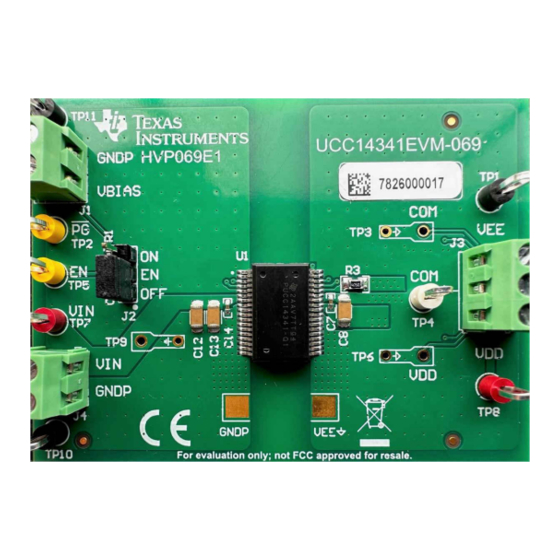
Page 29: Assembly And Printed Circuit Board (Pcb) Layers
6 Assembly and Printed Circuit Board (PCB) Layers The UCC14341EVM-069 is designed using a four-layer, FR4, PCB, fabricated with 2-ounce copper on all four layers. The EVM, PCB demonstrates the important use of ground planes and tented stitching vias for shielding and improving EMI performance. - Page 30 Assembly and Printed Circuit Board (PCB) Layers www.ti.com Figure 6-4. UCC14341EVM-069, PCB Top Layer, Assembly Figure 6-5. UCC14341EVM-069, GND Layer 2 (same as layer 3) Using the UCC14341EVM-069 for Biasing Traction Inverter Gate Driver ICs SLUUCS6 – FEBRUARY 2023 Requiring Single, Positive or Dual, Positive/Negative Bias Power Submit Document Feedback Copyright ©...
- Page 31 Assembly and Printed Circuit Board (PCB) Layers Figure 6-6. UCC14341EVM-069, GND Layer 3 (same as layer 2) Figure 6-7. UCC14341EVM-069, PCB Bottom Layer, Assembly (mirrored view) SLUUCS6 – FEBRUARY 2023 Using the UCC14341EVM-069 for Biasing Traction Inverter Gate Driver ICs...
-
Page 32: Bill Of Materials (Bom)
Instruments Capacitor, ceramic, 35 V, +/- 10%, X7R, 10 µF, AEC-Q200 CGA5L1X7R1V106K160AC Grade 1, 1206 Using the UCC14341EVM-069 for Biasing Traction Inverter Gate Driver ICs SLUUCS6 – FEBRUARY 2023 Requiring Single, Positive or Dual, Positive/Negative Bias Power Submit Document Feedback... - Page 33 TI products. TI’s provision of these resources does not expand or otherwise alter TI’s applicable warranties or warranty disclaimers for TI products. TI objects to and rejects any additional or different terms you may have proposed. IMPORTANT NOTICE Mailing Address: Texas Instruments, Post Office Box 655303, Dallas, Texas 75265 Copyright © 2023, Texas Instruments Incorporated...
Need help?
Do you have a question about the UCC14341EVM-069 and is the answer not in the manual?
Questions and answers