Sign In
Upload
Manuals
Brands
Texas Instruments Manuals
Motherboard
UCC5870QDWJEVM-026
Texas Instruments UCC5870QDWJEVM-026 Manuals
Manuals and User Guides for Texas Instruments UCC5870QDWJEVM-026. We have
1
Texas Instruments UCC5870QDWJEVM-026 manual available for free PDF download: User Manual
Texas Instruments UCC5870QDWJEVM-026 User Manual (34 pages)
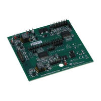
Evaluation Module for Gate Driver UCC5870-Q1
Brand:
Texas Instruments
| Category:
Motherboard
| Size: 3 MB
Table of Contents
Table of Contents
1
General TI High Voltage Evaluation User Safety Guidelines
3
Description
5
O Description
5
Electrical Specifications
6
Jumpers Setting
6
UCC5870 EVM Electrical Specifications
6
Test Summary
7
Default Jumper Settings for EVM MCU Daughter Board (Regular Mode SPI)
7
Jumper Settings for EVM MCU Daughter Board (Address Mode SPI and Daisy Chain Mode SPI)
8
Default Jumper Settings for EVM Driver Board
8
Low Voltage Bench Setup Configuration
9
Test Points Labels for J22
9
Low Voltage Test Procedure Example
10
Gui
10
GUI EVM Number and SPI Mode Select
11
GUI High Side or Low Side Driver Selection
11
GUI Configuration 1
12
GUI Configuration 2
12
GUI Configuration 2 Read All Registers
13
GUI Configuration 2 Disable DESAT Protection
13
GUI Configuration 2 Disable Gate Voltage Monitor Function
14
GUI Active State Enable Continuous PWM
14
Continuous PWM Waveforms
15
GUI Active State Double Pulses Test
15
Double Pulses Test Waveforms
16
GUI Configuration 2 Enable DESAT Protection
16
GUI Active Stage Fault Indicator
17
DESAT Fault Test Waveforms
17
Status Register Shows DESAT Fault
18
Clear Fault Option
18
Daisy Chain SPI Mode Selection
19
Daisy Chain SPI Mode High Side CF1 State
19
Daisy Chain SPI Mode Low Side CF1 State
20
Daisy Chain SPI Mode High Side and Low Side CF2 State
20
Address SPI Mode Selection
21
Address SPI Mode High Side CF1 State: Writing Address 0X01
21
Address SPI Mode High Side CF2 State
22
Address SPI Mode Low Side CF1 State: Writing Address 0X02
22
High Voltage Test Example
23
EVM Primary and Secondary
23
EVM Connected with IGBT Module
24
Double Pulses Test Waveforms at 400V 100A
24
Schematic
25
UCC5870 EVM Low Side Driver Schematic
25
UCC5870 EVM High Side Driver Schematic
26
Layout Diagrams
27
PCB Layout Top Overlay
27
PCB Layout Top Layer
27
PCB Layout Inter Layer 1
28
PCB Layout Inter Layer 2
28
PCB Layout Inter Layer 3
29
PCB Layout Inter Layer 4
29
PCB Layout Bottom Layer
30
PCB Layout Bottom Overlay
30
Bill of Materials
31
List of Materials
31
Advertisement
Advertisement
Related Products
Texas Instruments UCC5304EVM-035
Texas Instruments UCC57108EVM
Texas Instruments UCC23513EVM-014
Texas Instruments UCC23313-Q1
Texas Instruments UCC27332Q1EVM
Texas Instruments UCC21710
Texas Instruments UCC21755-Q1
Texas Instruments UCC34141EVM-116
Texas Instruments UCC21750-Q1
Texas Instruments UCC14341EVM-069
Texas Instruments Categories
Motherboard
Control Unit
Microcontrollers
Computer Hardware
Calculator
More Texas Instruments Manuals
Login
Sign In
OR
Sign in with Facebook
Sign in with Google
Upload manual
Upload from disk
Upload from URL