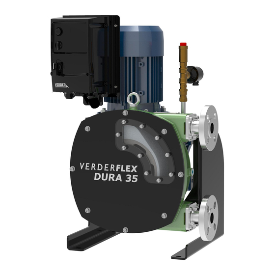
Summary of Contents for Verderflex iDura 5
- Page 1 Peristaltic Industrial Hose Pump Supplementary iDura Document 5, 7, 10, 15, 25, 35 Version 1.0v-11/2020 Print-No.
- Page 2 Version 1.0v-11/2020 Print-No. 01 5, 7, 10, 15, 25, 35 The information in this document is essential for the safe operation of Verderflex Dura pumps. ® i This document must be read and understood thoroughly prior to installation of unit, electrical con- nection and commissioning.
-
Page 3: Table Of Contents
Table of Contents About this Document Target Groups Warnings and Symbols Used in the Manual Safety Intended Use General Safety Instructions 2.2.1 Product Safety 2.2.2 Obligation of the Operating Company 2.2.3 Obligation of Personnel Specific Hazards 2.3.1 Hazardous Pumped Liquids 2.3.2 Lubricants 2.3.3... -
Page 4: About This Document
About this Document This manual is a guideline for qualified users for the safe operation and maintenance of Verderflex iDura pumps. This is a sup- ® plementary document to the Dura operating manual and the Inverter instruction manual. The operating manuals must be read and understood both by the installing personnel and the responsible trained personnel / operators prior to following additional guidelines in this document. -
Page 5: Safety
Safety • In the event of any safety-relevant faults, shut down the pump immediately and have the malfunction corrected by qualified personnel. The manufacturer does not accept any liability for damage • The installation of the pump must comply with the require- resulting from disregard of this documentation as well as ments of installation given in this manual and any local, instructions in pump, motor, gearbox and inverter manu-... -
Page 6: Specific Hazards
Warranty The warranty is void if the customer fails to follow any Instruction, Warning or Caution in this document. Verder has made every effort to illustrate and describe the prod- uct in this document. Such illustrations and descriptions are however, for the sole purpose of identification and do not express or imply a warranty that the products are mer- chantable or fit for a particular purpose, or that the prod- ucts will necessarily conform to the illustration or descrip-... -
Page 7: Transport, Storage And Disposal
Transport, Storage and Storage Conditions Disposal Make sure the storage location meets the following Transport conditions: – Dry, humidity not to exceed 85%, non-condensing – Out of direct sunlight Always transport the pump in a stable position and ensure – Frost-free;... -
Page 8: Electrical Safety
4.2 Electric Shock Hazard Disposal Disconnect and ISOLATE the Inverter before attempting With prolonged use, pump parts can be contaminated any work on it. by hazardous pumped liquids to such an extent that cleaning High voltages are present at the terminals and within the may be insufficient. -
Page 9: Connecting To The Power Supply
5 Operation (supplementary) 4.3 Connecting to the Power Supply Select the correct specification of cable for connecting the Check inverter directional switch (1) is in central “0” posi- inverter (g Refer to the Invertek manual for cable instal- tion and that power is available to the inverter. lation guidance) Switch on the inverter using the built-in isolator switch and check no errors are displayed on screen. -
Page 10: Maintenance
Maintenance Set directional dial to whichever direction is preferable, and the speed dial to minimum setting. The motor will slowly drive out the hose. If at this point you Only trained service technicians should be employed are performing inspection on the rotor or pump cavity, turn for fitting and repair work. -
Page 11: Service And Inspection Of Electrical Components
No further wiring has to be done by the user to use the hose burst detection. Verderflex hose burst detector and vent kit provide three basic functions: Stops the pump in conjunction with the inverter, in case of accidental hose burst;... -
Page 12: Idura Inverter Functionality
8.2 iDura Inverter Functionality Values set during assembly at Verder should not be changed. These have been determined to be specific to the selected hardware. Some functionality in the inverter can be set by the customer to make it work with their system and control method, though the following parameters should not be changed and will result in warranty being voided if changed: Parameter Description... -
Page 13: Appendix A - Idura
8.2 iDura Inverter Functionality (continued) Parameter Description User can change? Serial communications configuration Access code definition Yes* Parameter access lock Analog input 1 offset Display scaling PI controller proportional gain PI controller integral time PI controller operating mode PI reference source select PI control wake up error level User output relay hysteresis Motor control mode... - Page 14 List of Figures and Tables List of Figures Figure 1 Fastening Lifting Gear to Pump 3.1.2 Figure 2 Wiring Diagram - Single and 3 Phases Supply Figure 3 iDura Inverter Overview List of Tables Table 1 Target Groups Table 2 Warnings Used in the Manual Table 3 Symbols Used in the Manual...
- Page 15 10 EC Declaration of Conformity EC declaration of conformity according to machinery directive, appendix II A VERDER Ltd., Unit 3 California Drive, Castleford hereby declare that the following machine adheres to the relevant EC directives detailed below Designation iDura MK IV 05 iDura MK IV 07 iDura MK III 10 iDura MK III 15...
-
Page 16: Technical Specifications
11.7 Rotor Options Position Torque Values (Nm) iD5,7,10 iD15 iD25 iD35 Verderflex iDura 5-35 range has only standard pressure Motor foot bolts rotor as follows: Motor plate bolts Pump Type Rotor Option (bars) - Page 17 12 Trademarks VERDERFLEX is a registered trademark of Verder International B.V. No permission is granted to use any Verder, trademarks or ® trade names included in this document without the prior written agreement of Verder International B.V. Modbus is a registered trademark of Schneider electric USA, INC.


Need help?
Do you have a question about the iDura 5 and is the answer not in the manual?
Questions and answers