
Subscribe to Our Youtube Channel
Related Manuals for Verderflex Dura 7


Summary of Contents for Verderflex Dura 7
- Page 1 Peristaltic Industrial Hose Pump Operating Manual Dura 5, 7, 10, 15, 25, 35 Version 4.0v-06/2013 Print No.
- Page 2 Dura 5, 7, 10, 15, 25, 35 Print-No. 01 The information in this document is essential for the safe operation and servicing of Verderflex® Dura pumps. This document must be read and understood thoroughly prior to installation of unit, electrical connection and commissioning.
-
Page 3: Table Of Contents
Table of contents Table of contents About this document Operation Target groups Pre-commissioning the pump Warnings and symbols 6.1.1 Checking the direction of rotation with dry pump Safety 6.1.2 Starting the pump Intended use 6.1.3 Switching off General safety instructions Operation 2.2.1 Product safety... -
Page 4: About This Document
About this document About this document Verderflex range of Peristaltic pumps, Dura 5 - 35, has been developed according to the latest technology and subject to continuous quality control. These operating instructions are intended to facilitate familiarization with the pump and its designated use. The relevant information will act as a guideline for you in operating the pump;... -
Page 5: Safety
Safety Keep this manual and all other applicable documents Safety complete, legible and accessible to personnel at all times. Refrain from any procedure or action that would pose a risk The manufacturer does not accept any liability for to personnel or third parties. damage resulting from... -
Page 6: Obligation Of Personnel
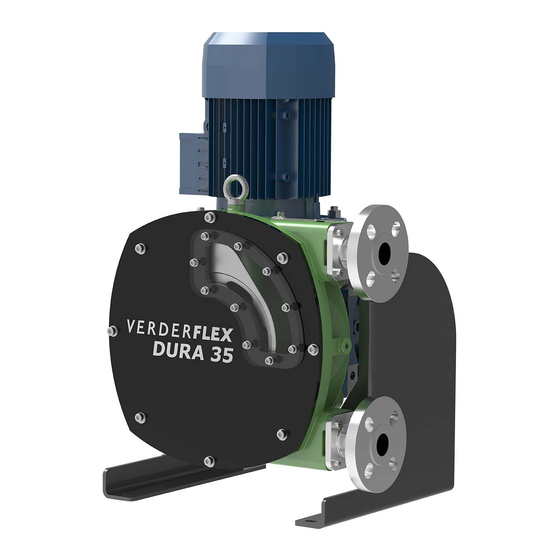
Design details 2.2.3 Obligation of personnel Verderflex Dura is a twin lobe, single rotor, peristaltic It is imperative that the instructions contained in pump with quick-fit tapered port flange design which this manual are complied with by the operating clamps and seals in one easy movement to speed personnel at all times. -
Page 7: Layout
Layout and function Layout Figure 2 Layout (generic view) Inspection window Front Bearing Torque arm Inspection window gasket Pump casing Drive shaft Front cover Lifting eye Frames Hose Port flange Gearbox Rotor Bearings Motor Crescent clip Lip seal Bearings and Lubrication ... -
Page 8: Transport, Storage And Disposal
Transport, storage and disposal Transport Always transport the unit in an upright position and ensure that the unit is securely attached to the pallet. 4.1.1 Unpacking and inspection on delivery Unpack the pump/pump unit upon delivery and inspect it for transport damage. Report any transport damage to the manufacturer/distributor immediately. -
Page 9: Treatment For Storage
Treatment for storage Installation and connection Unpainted steel surfaces should be coated with rust inhibitor and the unit should be stored in a dry, dust free environment not exceeding 60°C NOTE Material damage due to unauthorized modification on NOTE pump unit! ... -
Page 10: Planning The Pipes
Planning the pipes Do’s Don’t 5.3.1 Specifying supports and flange connections 1. Short pipe run to Long pipe run to suction suction side side When planning pipe runs take every possible operating condition into account: – Cold/warm medium – Empty/full –... -
Page 11: Assembling The Pump
Assembling the pump 5.4.1 Assembling pump case Using a bearing press, press the bearings squarely into the front and rear of the pump body until they locate on the shoulders in the pump housing. Figure 6 Fitting the frames 5.3.2 Installing the drive shaft Apply some triple life bearing grease (Roccol Figure 4... -
Page 12: Installing The Rotor
Figure 9 Inserting the crescent ring Figure 11 Inserting the O-ring (front cover assembly) Once the drive shaft is in place the crescent ring When fitting the front cover, the cap head screw nearest to the inspection window, is fitted without a groove should become visible at the rear of the pump. -
Page 13: Assembling Gear Motor Unit
Secure the inspection window to the front cover with Align the drive shaft key and GMU keyway; then slide cap head screws. Care must be taken not to over the GMU over the drive shaft. tighten the screws, as this may damage the inspection window (Refer table 11 Tightening torques ). -
Page 14: Electrical Connection
Add some lubricant to the pump housing. Electrical connection Lubricate the hose generously with Verderlube / Verdersil. DANGER Insert the hose into the lower port. Risk to health due to electric shock! Run the pump forward until the hose is fed through the ... -
Page 15: Fitting The Port Flange (Split Flange Assembly)
Rotate the rotor slowly in a direction to feed the hose Connecting the pipes onto the taper. Tighten all 4 bolts fully to clamp the hose and ensure NOTE the hose can be seen through the aperture in the side Contamination of pumped media due to impurities in the of casing formed between the flange and the casing. -
Page 16: Operation
6.1.3 Switching off Operation NOTE Risk of dead heading and hose burst due to closed Pre-commissioning the pump suction or discharge! Keep the suction and discharge side fittings opened till 6.1.1 Checking the direction of rotation with dry the rotor has come to a complete stop. pump WARNING Ensure the pump has lubricant in it... -
Page 17: Switching Off (Refer To → 6.1.3)
Switching off (Refer to → 6.1.3) 6.2.2 Behavior of Duration of shutdown (depending WARNING the pumped on process) liquid Risk of injury due to hot pump parts! Short Long Use personal protective equipment when carrying out Flush the ... -
Page 18: Start-Up Following A Shutdown
Start-up following a shutdown Maintenance period These pumps are generally maintenance free and any work should normally be limited to inspections After a prolonged shutdown period, re-commission the and pump lubricant changes as required; these may pump as follows: be more frequent in dust and/or hot condition. –... -
Page 19: Maintenance Schedule
Maintenance 7.2.2 Maintenance schedule Task Frequency Action Check pump and gearbox for leaks and – Before pump start up Repair leaks and damage before damage operating the pump – Daily visual inspection Replace components as necessary. – Scheduled intervals during operation ... -
Page 20: Repairs
Repairs 7.3.2 Returning the pump to the manufacturer Pump unpressurized Completely emptied and decontaminated. DANGER Pump cooled down Risk of death due to electric shock! Hose dismounted (→ 7.4.1 Dismounting the hose) Have all electrical work carried out by qualified electrician only Obtain prior authorization before repair or return of the pump. -
Page 21: Rebuild / Repair
Removing the hose 7.3.3 Rebuild / Repair Reinstall the components, in accordance with the CAUTION marks applied. Risk of injury if the hose is expelled too quickly Slowly remove the hose by running the motor at a NOTE reduced speed Material damage due to unsuitable components! ... -
Page 22: Ordering Spare Parts
Lubricants should be stored under normal warehouse Storing pumps and hoses conditions with their caps securely fastened. Verderflex pumps are designed for continuous use, however, there may be instances when pumps are withdrawn from use and stored for extended periods. -
Page 23: Troubleshooting
Troubleshooting Pump malfunctions If malfunctions occur which are not specified in the following table or cannot be traced back to the specified causes, please consult the manufacturer. Possible malfunctions are identified and respective cause and remedy are listed in the table. Dura 5 - 35 4.0v-06.2013 23 | Page... - Page 24 Troubleshooting Possible Cause Remedy Incorrect lubricant Consult the manufacturer to obtain correct lubricant. Low lubricant level Add required amount. Product ambient temperature too high Consult the manufacturer regarding maximum temperature. Over shimming of the pump Check for and remove excess shims. ...
-
Page 25: 10. Appendix
Relative humidity – long—term ≤ 85 % 10.1.7 Rotor options Setup height above sea level ≤ 1000 Verderflex Dura 5-35 range has standard and high pressure rotor options: Storage conditions Rotor option (bars) Ambient temperature +10 °C to +50 °C... -
Page 26: List Of Figures And Tables
List of figures and tables 10.2 List of Figures and Tables 10.2.1 List of figures Figure 1 Name plate 3.2.1 Figure 2 Layout (Generic view) Figure 3 Fastening lifting gear to pump unit 4.1.2 Figure 4 Inserting shaft seal 5.4.1 Figure 5 Fitting the filler tube 5.4.1... -
Page 27: Machine Directive
Appendix 10.3 Declaration of conformity according to EC Machine Directive EC declaration of conformity according to machine directive, appendix II A VERDER Ltd., Unit 3 California Drive, Castleford hereby declare that the following machine adheres to the relevant EC directives detailed below Designation Dura 05 Dura 07... - Page 28 Dura 5 - 35 4.0v-06.2013 28 | Page...
Need help?
Do you have a question about the Dura 7 and is the answer not in the manual?
Questions and answers