Advertisement
Available languages
Available languages
Table of Contents
- 1 Table of Contents
- 2 Version 7.01 January
- 3 Assembly
- 4 Assembling the Pump
- 5 Hose Installation
- 6 Other Information
- 7 Appendix A - VERDERLUBE Safety Data Sheet
- 8 Appendix B - VERDERSIL Safety Data Sheet
- 9 Appendix C - DURA10 Replacement Parts & Kits
- 10 Appendix G - Exploded View and Construction Details
- 11 Verz E 7.01 Leden
- Download this manual
Advertisement
Table of Contents

Subscribe to Our Youtube Channel
Related Manuals for Verderflex DURA Series


Summary of Contents for Verderflex DURA Series
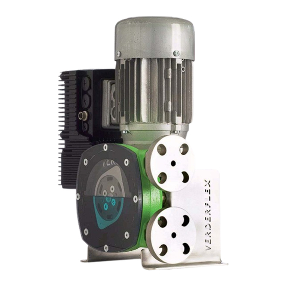
- Page 1 ® ® VERDERFLEX Dura Peristaltic Hose Pump VERDER Ltd, Whitehouse Street, Hunslet, Leeds, LS10 1AD • Tel: (44) 0113 222 02 50 • Fax: (44) 0113 222 02 91 • E-mail: info@verderflex.co.uk...
- Page 2 ® ® Hadicové þerpadlo VERDERFLEX Dura BIA- VERDER s.r.o, Vod anská 651/5 (vchod Chlumecká 15), Praha 9. Tel. 261 225 386-7. Fax. 261 255 121. info@bia-verder.cz, www.bia-verder.cz...
-
Page 3: Table Of Contents
Operation, Maintenance & Safety Manual Version 7.01 January 2006 TABLE OF CONTENTS Introduction Safety Issues Theory of the Pump Safety, Operation and Maintenance Instructions 4.2.1 Assembly 4.2.2 Preparation 4.2.3 Assembling the pump 4.6.1 Hose - Removal and Installation 4.6.2 Hose Removal 4.6.3 Hose Installation 4.6.4... - Page 4 N ávod k obsluze a údržb Verz e 7.01 Leden 2006 O BSAH Ú vod B ezpeþnost T eoretické informace o þerpadle Pokyny k bezpeþné obsluze a údržb 4.2.1 M ontáž 4.2.2 P íprava 4.2.3 M ontáž þerpadla 4.6.1 Ha dice - V yjmutí a instalace 4.6.2 Vyjmutí...
-
Page 5: Version 7.01 January
Operation, Maintenance & Safety Manual Version 7.01 January 2006 Safety Issues 2.1 Safety Alert Symbol The symbol shown above is used to identify topics of primary safety concern and call attention to instructions concerning your personal safety. Watch for this symbol, it involves important safety precautions, and means “ATTENTION! BE ALERT! YOUR PERSONAL SAFETY IS INVOLVED!”... - Page 6 N ávod k obsluze a údržb Verz e 7.01 Leden 2006 Bezpeþnost 2.1 Symbol bezpeþnostního upozorn ní Výše zobrazený symbol vždy p ipomíná dodržování základních pravidel bezpeþnosti a upozor uje na pokyny týkající se bezpeþnosti osob. Všímejte si tohoto symbolu, upozor uje vždy na dodržování...
- Page 7 • ® ® Maintain a clean environment around the pump. The VERDERFLEX Dura pump is manufactured from cast steel, and therefore the flanges and Housings etc may have sharp edges - slipping or falling against the pump may cause serious injury.
- Page 8 þerpadla nedotýkejte, dokud není úpln odpojeno od p ívodu elektrického proudu! • Kolem þerpadla udržujte þistotu. ýerpadlo VERDERFLEX® Dura® je vyrobeno z litinové oceli, a proto mohou mít p íruby a pláš þerpadla ostré hrany - p i p ejížd ní rukou po þerpadle nebo p i jeho pevném uchopení...
-
Page 9: Assembly
Version 7.01 January 2006 3.4 Product Range ® ® The VERDERFLEX Dura range of pumps are sized and named according to the internal bore diameter of the hose. The range starts with the 10mm diameter DURA10 unit, and incorporates a total of 3 models, up to the 25mm diameter DURA25. - Page 10 VERDERFLEX Dura ® ® Hadicová þerpadla výrobní ady VERDERFLEX Dura jsou pojmenována a velikostn odstup ována podle vnit ního pr m ru hadice. Rozsah výrobní ady zahrnuje celkem 3 modely þerpadel, zaþíná þerpadlem DURA 10 s pr m rem hadice 10 mm a konþí þerpadlem DURA 25 s pr m rem hadice 25mm.
-
Page 11: Assembling The Pump
Operation, Maintenance & Safety Manual Version 7.01 January 2006 4.2.3 Assembling the pump Figure 2a Before assembling the pump it is advised to clean down the cavity of the pump body to remove any debris. Figure 2b Using a bearing press, press the bearings into the front and rear of the pump body. - Page 12 N ávod k obsluze a údržb Verz e 7.01 Leden 2006 4.2.3 Montáž þerpadla O br. 2a P ed montáží þerpadla je doporuþeno oþistit vnit ní plochy souþástí t lesa þerpadla od všech úlomk , prachu a špon z výroby. O br.
- Page 13 Operation, Maintenance & Safety Manual Version 7.01 January 2006 Figure 2e Mount the framework to pump body, use 4 of the cap head bolts. Although this will give the assembly a certain amount of rigidity once stood upright the pump could tip forward.
- Page 14 N ávod k obsluze a údržb Verz e 7.01 Leden 2006 O br. 2e K t lesu þerpadla p ipevn te rám , p oužijte 4 šrouby s p lkulatou hlavou . M ontáží tohoto rámu získá konstrukce þásteþnou stabilitu, nicmén p i postavení do provozní polohy m že dojít k p evrácení.
-
Page 15: Hose Installation
Operation, Maintenance & Safety Manual Version 7.01 January 2006 Figure 2i Before inserting the hose the O-ring and front cover needs attaching. The O-ring should sit securely in the groove located around the front of the pump body. Figure 2j The front cover should bolt in place with the use of 8 countersunk hex bolts, observe the relevant torque of 2Nm. - Page 16 N ávod k obsluze a údržb Verz e 7.01 Leden 2006 O br. 2i P ed vložením hadice vložte peþliv do drážky kolem þela t snící O-kroužek a p ipevn te p ední þerný kryt þerpadla . O br. 2j ýelní...
- Page 17 Operation, Maintenance & Safety Manual Version 7.01 January 2006 Figure 2m When sliding the GMU onto the drive shaft it may be advisable to use suitable lifting equipment. To make the process of aligning the GMU easier it may be advisable to remove the motor fan cowel and turn the fan until the key and keyway align with the end of the shaft.
- Page 18 N ávod k obsluze a údržb Verz e 7.01 Leden 2006 O br 2m P i nasazování motoru s p evodovou jednotkou na hnací h ídel je vhodné použít zdvihací za ízení. Pro usnadn ní nasazení m žete sejmout kryt ventilátoru motoru a pomocí...
- Page 19 Operation, Maintenance & Safety Manual Version 7.01 January 2006 • Lift the pump into position and bolt to foundations securely, ensuring that the pump and drive assembly is supported to enable a balanced, vertical lift. • Only a qualified person should carry out electrical installation! •...
- Page 20 N ávod k obsluze a údržb Verz e 7.01 Leden 2006 • ýerpadlo p esu te na místo jeho instalace a bezpeþn p ipevn te kotvícími šrouby k po d ložce, v nujte p itom pozornost správnému vyvážení a vyrovnání þerpadla a motoru . •...
- Page 21 Operation, Maintenance & Safety Manual Version 7.01 January 2006 4.4 Commissioning • Check all nuts and bolts are tightened to the required torque settings. • Before connecting the pump to pipe work, run the pump dry for 10 - 20 revolutions in both directions to ensure that the hose is secured properly.
- Page 22 N ávod k obsluze a údržb Verz e 7.01 Leden 2006 4.4 Uvedení do provozu • Z kontrolujte, zda jsou všechny šrouby a spoje dotaženy p edepsaným momentem . • P ed p ipojením þerpadla na potrubí jej nechte 10 - 20 otáþek b žet nasucho v obou sm rech otáþení, abyste se ujistili, že je hadice v þerpadle správn umíst na a p ipojena .
- Page 23 Operation, Maintenance & Safety Manual Version 7.01 January 2006 4.6.3 Hose Installation • Never install a hose without the front cover in place! • Fully lubricate the outer wall of the hose to aid installation. Insert one end of the hose in the mouth of the inlet port (the hose should be fed into the pump in the direction of normal operation).
- Page 24 N ávod k obsluze a údržb Verz e 7.01 Leden 2006 4.6.3 Instalace hadice • N ikdy hadici neinstalujte, pokud p edtím nebyl p ipevn n þelní kryt þerpadla ! • P ro usnadn ní instalace namažte celý povrch hadice. Jeden konec hadice vložte do ústí sacího otvoru þerpadla (hadice by m la být vložena do þerpadla ve sm ru otáþek b žného provozu.
- Page 25 Operation, Maintenance & Safety Manual Version 7.01 January 2006 Figure 4 • With the hose in position the taper-lock flanges can be fitted. With the four bolts tightened up correctly there should be a gap between the taper-lock flange and the housing of typically 2- 4mm, as shown in Figure 5.
- Page 26 N ávod k obsluze a údržb Verz e 7.01 Leden 2006 O br. 4 • Po správném umíst ní hadice m žou být p ipevn ny p íruby sacího a výtlaþného potrubí. Po dotažení všech þty ech šroub p íruby by m la mezi plochou p íruby a ústím sacího i výtlaþného potrubí...
- Page 27 Operation, Maintenance & Safety Manual Version 7.01 January 2006 • It must be noted that the relationship between correct torque and finish gap can vary due to component tolerances. The effort to reach the torque should not override this, as the torque figure is a maximum figure and not the minimum requirement.
- Page 28 N ávod k obsluze a údržb Verz e 7.01 Leden 2006 • Je pot eba poznamenat, že závislost mezi požadovaným utahovacím momentem a výslednou mezerou m že být ovlivn na výrobními odlišnostmi jednotlivých souþástí. Není úþelné se snažit o dosažení hodnoty utahovacího momentu, protože uvád né jsou jeho maximální hodnoty a nikoliv minimální...
- Page 29 Operation, Maintenance & Safety Manual Version 7.01 January 2006 4.6.4 Front Cover Installation The front cover sits against a rubber O-Ring. Please note the front cover could split if the bolts attaching it to the housing are over tightened. It is therefore important that the instruction below is followed: •...
- Page 30 N ávod k obsluze a údržb Verz e 7.01 Leden 2006 4.6.4 I nstalace þelního krytu þerpadla ýelní kryt þerpadla dosedá a je dotažen p es t snící pryžový O-kroužek. P i dotahování šroub krytu postupujte opatrn , protože p i jejich nadm rném dotažení m že kryt prasknout. Držte se následujících pokyn : •...
- Page 31 Operation, Maintenance & Safety Manual Version 7.01 January 2006 4.9 Fault Finding PROBLEM CAUSE CORRECTIVE ACTION Abnormally high Non-standard lubricant Consult VERDER distributor to obtain correct pump temperature lubricant Low lubricant level See lubrication levels in section 4.8, add required amount Product temperature too Consult VERDER distributor regarding high...
- Page 32 N ávod k obsluze a údržb Verz e 7.01 Leden 2006 4.9 Odstra ování závad PROBLÉM P ÍýINA P OSTUP ODSTRAN NÍ Nezvykle vysoká Nestandardní mazivo U vašeho prodejce þerpadel VERDER si po teplota þerpadla konzultaci objednejte správný typ maziva Nízká...
-
Page 33: Other Information
Customer care is one of VERDER’s top priorities Distributor Contact Details: VERDER Contact Details: VERDER Ltd Whitehouse Street Leeds LS10 1AD ENGLAND, UK Tel: (+44) 113 222 0279 Fax: (+44) 113 222 0291 E-mail: info@verderflex.com Web Site: www.verderflex.com... - Page 34 VERDER. K ontaktní informace prodejce : K ontaktní informace spoleþnosti VERDER : VERDER Ltd Whitehouse Street Leeds LS10 1AD ENGLAND, UK Tel: (+44) 113 222 0279 Fax: (+44) 113 222 0291 E-mail: info@verderflex.com Web: www.verderflex.com...
-
Page 35: Appendix A - Verderlube Safety Data Sheet
Version 7.01 January 2006 Appendix A - VERDERLUBE Safety Data Sheet ® VERDERLUBE is the lubricant / coolant used with the VERDERFLEX range of and other peristaltic or hose pumps Used lubricant may become contaminated with pumped product, also verify precautions and advice... - Page 36 P íloha A - Mazivo VERDERLUBE - bezpeþnostní informace VERDERLUBE j e speciální typ maziva / chladící kapaliny urþené pro þerpadla výrobní ady ® VERDERFLEX i ostatní typy peristaltických a hadicových þerpadel. V pr b hu þinnosti þerpadla m že dojít ke kontaminaci maziva þerpanou látkou. Postupujte vždy podle p íslušných pokyn a zjist te si pot ebné...
-
Page 37: Appendix C - Dura10 Replacement Parts & Kits
Operation, Maintenance & Safety Manual Version 7.01 January 2006 Appendix C - DURA10 Replacement Parts & Kits PART TORQUE QUANTITY Drive Shaft – 139.0554 Drive Shaft Mounted in Housing Crescent Ring Kit – 139.0161 Crescent ring H30 N/A Securing Drive Shaft in Housing Crescent ring H14 N/A Securing GMU to Drive Shaft Universal Flanges (To suit ANSI, JIS &... - Page 38 N ávod k obsluze a údržb Verz e 7.01 Leden 2006 P íloha C DURA10 Náhradní díly – O.þ. SOU ý ÁST T Oý. MOM. P OUŽITÍ P OýET H nací h ídel – 139.0554 Hnací h ídel Uložena v ložisku plášt H ídelové...
-
Page 39: Appendix G - Exploded View And Construction Details
Operation, Maintenance & Safety Manual Version 7.01 January 2006 Appendix G - Exploded View and Construction Details... -
Page 40: Verz E 7.01 Leden
N ávod k obsluze a údržb Verz e 7.01 Leden 2006 P íloha G - Detailní zobrazení konstrukþního uspo ádání... - Page 41 Operation, Maintenance & Safety Manual Version 7.01 January 2006 NUMBER PART DESCRIPTION QUANTITY Casing Cast Steel Rotor Cast Steel Drive Shaft EN24 Universal Flange 316 Stainless Steel LH Frame 3mm Stainless Steel RH Frame 3mm Stainless Steel Front Cover Toughened Polycarbonate Torque Arm 4mm Mild Steel Cap Head Screw...
- Page 42 N ávod k obsluze a údržb Verz e 7.01 Leden 2006 ýÍSLO ý ÁST P OPIS MNOŽSTVÍ P láš L itina Rotor L itina H nací h ídel EN24 U niverzální p íruba 316 N erezová ocel LH R ám Nerezová...
Need help?
Do you have a question about the DURA Series and is the answer not in the manual?
Questions and answers