
Related Manuals for Omron SYSMAC CVM1-PRO01-V1


Summary of Contents for Omron SYSMAC CVM1-PRO01-V1
- Page 1 Cat. No. W320-E1-03 SYSMAC CVM1-PRO01-V1 Teaching Box with CVM1-MP702-V1 ROM Cassette (For Motion Control Units)
- Page 2 SYSMAC CVM1-PRO01-V1 Teaching Box with CVM1-MP702-V1 ROM Cassette (For Motion Control Units) Operation Manual Revised August 2002...
- Page 4 OMRON. No patent liability is assumed with respect to the use of the information contained herein. Moreover, because OMRON is constantly striving to improve its high-quality products, the information contained in this manual is subject to change without notice.
-
Page 6: Table Of Contents
TABLE OF CONTENTS PRECAUTIONS ....... . . 1 Intended Audience . - Page 7 TABLE OF CONTENTS SECTION 7 EXTENSION Mode Operations ....EXTENSION Mode ............Servo-lock/Unlock .
- Page 8 About this Manual: This manual describes the installation and operation of the CVM1-PRO01-V1 Teaching Box and includes the sections described below. In particular it describes the operation of the Teaching Box when it is con- nected to a Motion Control Unit. The CVM1-PRO01-V1 Teaching Box is a Programming Device for CS1-series PCs and C/CV-series PCs and is used with the CV500-MC221, CV500-MC421, C200H- MC221, CS1W-MC221, and CS1W-MC421 Motion Control Units.
- Page 9 Section 1 contains information on the Teaching Box functions and a list of key names and their functions. Section 2 explains the operating principles, ways of delivering instructions, Motion Control Unit modes, and the operations that can be performed using the Teaching Box. Be sure that you understand all of the subjects covered in this section before attempting any actual operations.
-
Page 10: Precautions
PRECAUTIONS This section provides general precautions for using the Programmable Controller (PC) and related devices. The information contained in this section is important for the safe and reliable application of the PC. You must read this section and understand the information contained before attempting to set up or operate a PC system. 1 Intended Audience . -
Page 11: Intended Audience
This manual provides information for programming and operating OMRON PCs. Be sure to read this manual before attempting to use the software and keep this manual close at hand for reference during operation. -
Page 12: Application Precautions
Application Precautions Application Precautions Observe the following precautions when using MC Unit, PCU, Teaching Box, or WARNING Do not attempt to take the Unit apart while the power is being supplied. Doing so may result in electric shock. WARNING Do not touch any of the terminals while the power is being supplied. Doing so may result in electric shock. - Page 13 Application Precautions • Disconnect the functional ground terminal when performing withstand voltage tests. • Be sure to confirm that no adverse effect will occur in the equipment before executing Jog, Origin Search, Error Resetting, or Deceleration Stop. • Be sure to confirm that no adverse effect will occur in the equipment before changing the operation mode of the Teaching Box.
-
Page 14: Introduction
SECTION 1 Introduction This section contains information on the Teaching Box functions and a list of key names and their functions. If using the Teaching Box for the first time, be sure to familiarize yourself with this section before attempting to operate the Teaching Box. -
Page 15: Features And Applications
Features and Applications Section Features and Applications Features The CVM1-PRO01-V1 Teaching Box has the following features. Compatibility The Teaching Box can be used with MC Units, Position Control Units, and Posi- tion Drivers. Either an MC Unit or a Position Control Unit can be connected, de- pending on the type of Position Control Unit that is selected. -
Page 16: System Configuration
System Configuration Section System Configuration Teaching Box Connection Teaching Box CV500-CN22A/42A/62A CV500-CN224/424/624 Connecting Cable Connecting Cable CV500-CN224/424/624 Connecting Cable Position Driver Position MC Unit Control Unit CPU Unit CPU Unit Power Supply Unit CV500-CIF11/CIF21 Power Supply Unit Adapter CPU Unit Servodriver Servodriver Power Supply... - Page 17 Note 1. Dedicated Cables compatible with OMRON H, M, or U-series Servomotors are available. The user can also provide their own cables. 2. A Dedicated Cable for connections to the Dedicated Terminals is available. The user can also provide their own cable.
- Page 18 Note 1. Dedicated Cables compatible with OMRON H, M, or U-series Servomotors are available. The user can also provide their own cables. 2. A Dedicated Cable for connections to the Dedicated Terminals is available. The user can also provide their own cable.
- Page 19 Note 1. Dedicated Cables compatible with OMRON H, M, or U-series Servomotors are available. The user can also provide their own cables. 2. A Dedicated Cable for connections to the Dedicated Terminals is available. The user can also provide their own cable.
-
Page 20: Table Of Operations
Table of Operations Section Table of Operations The following tables list the operations of the Teaching Box. When CS1W-MC221/421 is Used Function Description Page Monitor Current position Monitors the following current positions: Current position in the reference coordinate system (using user-set units such as “mm.”) Current position in the reference coordinate system (in pulses.) Error counter value. - Page 21 Table of Operations Section When CV500-MC221/421 is Used Function Description Page Monitor Current position Monitors the following current positions: Current position in the reference coordinate system (using user-set units such as “mm.”) Current position in the reference coordinate system (in pulses.) Error counter value.
- Page 22 Table of Operations Section When C200H-MC221 is Used Function Description Page Monitor Current position Monitors the following current position: Current position in the reference coordinate system (using user-set unit such as “mm.”) Current position in the reference coordinate system (in pulses.) Error counter value.
-
Page 23: Nomenclature And Functions
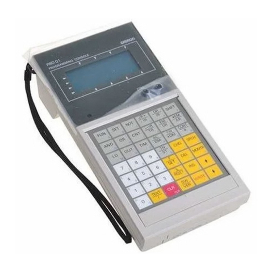
Nomenclature and Functions Section Nomenclature and Functions Shown below are the parts, functions, and key arrangement of the Teaching Box. Cable connector LCD display Contrast control knob LED indicator Volume control knob Direct command keys PAUSE START STOP TEACH Mode keys ORIG PROG TASK... - Page 24 Nomenclature and Functions Section Key Functions Classification Function Mode keys Monitors current position or I/O signals (MONITOR mode). ORIG Moves the selected axis to the origin (ORIGIN SRCH SEARCH mode). Jogs the selected axis (JOG mode). Designates the axis and multiplication factor when using a manual pulse generator (MPG mode).
-
Page 25: Precautions When Using The Cv500-Mc221
Precautions When Using the CV500-MC221 Section Precautions When Using the CV500-MC221 The operating procedures of the Teaching Box using the CS1W-MC421 MC Unit or the CS1W-MC221 MC Unit are respectively the same as those of the Teach- ing Box using the CV500-MC421 MC Unit or the CV500-MC221 MC Unit. Descriptions in this manual are given for the Teaching Box using the CS1W- MC421 or the CV500-MC421. -
Page 26: Operating Procedure
Operating Procedure Section Operating Procedure Follow the procedure outlined below to operate axes using the Teaching Box. Connect MC Unit Refer to Section 3-1 (When using for the first time after purchase, or when changing connected models.) Set connected models. Refer to Section 3-3 (see note 1) (When MC Unit has already... -
Page 27: Mc Unit Operation
SECTION 2 MC Unit Operation This section explains the operating principles, ways of delivering instructions, Motion Control Unit modes, and the operations that can be performed using the Teaching Box. Be sure that you understand all of the subjects covered in this section before attempting any actual operations. -
Page 28: Axes And Tasks
MC Unit Control Modes Section Axes and Tasks The axes for operation and tasks to be performed are described below. Motion Control The basic objects of motion control are the axes. Axes can be controlled either in combination or independently. Tasks A task is an executable unit of programming in MC programs. - Page 29 MC Unit Control Modes Section When the Tasks are controlled through the following three systems: the CX-Motion, lad- CS1W-MC221/421 or der-diagram program, and Teaching Box CV500-MC221/421 is The MC Unit may be processing commands from all the three systems at the Used same time.
-
Page 30: Restricted Functions
Restricted Functions Section Restricted Functions Some Teaching Box functions are restricted depending on the control mode of the MC Unit. The following tables show which functions are valid for each control mode. CS1W-MC221/421 Control mode Function T.BOX T.BOX T.BOX LIMITED ENABLED RESERVED Monitoring... - Page 31 Restricted Functions Section CV500-MC221/421 Function Control mode T.BOX T.BOX T.BOX LIMITED ENABLED RESERVED Monitoring Current position I/O signals See note 2 Error data Position data Z-phase tolerance Origin searches Program execution Jogging MPG (handle feeding) Extension Change mode Servo-lock/ Servo-unlock Memory protection Absolute encoder initial setting...
- Page 32 Restricted Functions Section C200H-MC221 Function Control mode T.BOX T.BOX T.BOX LIMITED ENABLED RESERVED Monitoring Present position I/O signals See note 2 Error data Position data See note 3 Z-phase tolerance Servo-parameters Origin searches Program execution Jogging MPG (handle feeding) Extension Change mode Servo-lock/ Servo-unlock...
-
Page 33: Connecting The Teaching Box
SECTION 3 Connecting the Teaching Box This section describes the procedures for connecting the Teaching Box, installing it on in a control panel, and changing dis- plays. Connecting to the MC Unit ..........Installing in a Panel . -
Page 34: Connecting To The Mc Unit
Connecting to the MC Unit Section Connecting to the MC Unit The procedure for connecting the Teaching Box to the MC Unit is described be- low. Note 1. Be sure that the power supply is turned OFF before mounting or removing the ROM Cassette. - Page 35 Connecting to the MC Unit Section Connecting to the MC Unit 1, 2, 3... 1. Remove the connector cover. Attach the removed cover to the rear surface so as not to lose it. Cover attached Open the cover using a Cover small-size flat-blade screwdriver.
-
Page 36: Installing In A Panel
Installing in a Panel Section Removing the Cable Using your fingers, press in and hold the clamps on both sides of the connector and pull out the connector. Unlocking clamps Adjusting the Buzzer and Turn the volume control knob to adjust the loudness of the buzzer. Display Contrast Turn the contrast control knob to adjust the contrast of the LCD display. - Page 37 Installing in a Panel Section 2. Provide sufficient spaces so that the connector can be easily connected or disconnected to/from the Teaching Box. 80 mm min. Use either one of the connectors. 70 mm min. 3. Mount the Teaching Box, aligning with the mounting holes and tighten the Mounting Bracket from the back side using screws.
-
Page 38: Selecting The Connected Model
Selecting the Connected Model Section Selecting the Connected Model Set the model that the Teaching Box is connected to. Select “MC Series” out of the following: • Servodriver (Position Driver) • MC Series (Motion Control) • 3G2A5-NC111-EV1 Position Control Unit •... -
Page 39: Changing The Display Language (English/Japanese)
Changing the Display Language (English/Japanese) Section Changing the Display Language (English/Japanese) Use this procedure to change the display language for the Teaching Box be- tween English and Japanese. CS1W-MC221/421 Changing of the display language is performed in the EXTENSION mode. When power is supplied the screen will be displayed in English. - Page 40 Changing the Display Language (English/Japanese) Section 5. Press the Up/Down Cursor Key to select English or Japanese as desired. EXT| LANGUAGE | ENGLISH | SWITCH:↑,↓ 6. Press the WRITE Key. From now on, messages will be displayed in the lan- guage selected.
- Page 41 Changing the Display Language (English/Japanese) Section 7. Press either “1” or “2.” Note Once the connections have been completed, setting of the connected device can be performed using the following operations when changing the display lan- guage between English and Japanese: •...
-
Page 42: Basic Operations
SECTION 4 Basic Operations This section contains information on the basic operations necessary for operating the Teaching Box. Be sure to read this sec- tion to fully understand the basic operations before reading detailed descriptions of each function given in subsequent sec- tions. -
Page 43: Initial Operation
Initial Operation Section Initial Operation This section describes the screen following power-up and explains online con- nection with the MC Unit. 1, 2, 3... 1. Turn ON the power to the PC. The following display will appear. TBOX V1.00 Teaching Box model and software version MC SERIES ↑:SET CLR:CONN... -
Page 44: Changing The Mc Unit Control Mode
Changing the MC Unit Control Mode Section Changing the MC Unit Control Mode Control Modes The MC Unit has three control modes; T.BOX LIMITED, T.BOX ENABLED, and T.BOX RESERVED. Note For details on these three modes, refer to 2-2 MC Unit Control Modes. The MC Unit is initially set to the T.BOX LIMITED mode, which allows only moni- toring from the Teaching Box. - Page 45 Changing the MC Unit Control Mode Section 1, 2, 3... 1. In the T.BOX RESERVED state, press “5.” An error message is displayed. CHANGE TO T.BOX A buzzer will sound when this error ENABLED OR T.BOX message appears. RESERVED MODE AND PROCEED.
-
Page 46: Changing The Teaching Box Mode
Direct Functions Section Changing the Teaching Box Mode The Teaching Box is initially set to the MONITOR mode. When operating the Teaching Box in another mode, change the mode using the mode keys. When the control mode of the MC Unit is set to T.BOX LIMITED, only monitoring is possible. -
Page 47: Basic Input Operations
Basic Input Operations Section Procedure The following procedure can be used to change the override value. Press the OVERRIDE Key. Example: CV500-MC421 or CS1W-MC421 The direct function name is represented by the two letters in parentheses. [OV]X 100.0 [OV]: Override 50.0 [TH]: Teaching 100.0... -
Page 48: Axis And Task Displays
Handling Error Messages Section • Press the CLR Key to return to the previous display. If the CLR Key is pressed while inputting numeric values, it will return the display to the previous numeric value. • Press the CLR Key several times to return to the initial display for the current modes. - Page 49 Handling Error Messages Section • Only the first task error detected for each task is displayed and stored in memory. • Only the first axis error detected for each axis is displayed and stored in memory. Error Display Example The buzzer sounds when an error message is displayed. <<<...
-
Page 50: Table Of Operations
Table of Operations Section Table of Operations The following table provides a summary of Teaching Box operations. Operations which appear in parentheses indicate operations which may be nec- essary, depending on the function and Teaching Box model used. Function Description Operation procedure Page Monitoring... - Page 51 Table of Operations Section Function Description Operation procedure Page Extension Changes the MC Unit control 62 to # / " 1 / 6 mode. Locks or unlocks the servomotor. Protects or clears memory protection for MC Unit # / " memory.
-
Page 52: Monitor Mode Operations
SECTION 5 MONITOR Mode Operations This section describes the methods for monitoring the various kinds of data. The procedure described in the first subsection is required for monitoring any type of data. Read the first subsection before reading any other subsection. MONITOR Mode . -
Page 53: Monitor Mode
MONITOR Mode Section MONITOR Mode The kinds of data shown in the following table can be monitored and changed in the MONITOR mode. CV500-MC221/421 Menu item Function Page 1. PRESENT POSITION Monitors the present position. 2. IN/OUT Monitors or changes I/O signals. 3. -
Page 54: Monitoring The Present Position
Monitoring the Present Position Section 3. Press the Down Key to see the remaining portion of the menu. CS1W-MC221/421 C200H-MC221 MON| MON| 4.POSITION DATA 4.POSITION DATA 5.Z PHASE TOLER 5.Z PHASE TOLER 6.SERVO PARAM 6.SERVO PARAM CV500-MC221/421 MON| 4.POSITION DATA 5.Z PHASE TOLER These two displays can be switched with the Up and Down Keys. -
Page 55: Monitoring And Changing I/O Signals
Monitoring and Changing I/O Signals Section For example, at an encoder resolution of 1,000 p/r, with an encoder multi- plication rate of 4, one revolution from the 0-pulse position would be as fol- lows: 1,000 x 4 = 4,000. • Deviation Counter Value (Pulses) CS1W-MC221/421, CV500-MC221/421 C200H-MC221 MON|X... - Page 56 Monitoring and Changing I/O Signals Section 2. Change the display using the Up and Down Keys. CS1W-MC221/421, CV500-MC221/421 C200H-MC221 MON| XYZU MON| IN |DRV ALRM0010 IN |DRV ALRM |STOP 0010 |STOP DRV alarm: Driver alarm input CS1W-MC221/421, CV500-MC221/421 C200H-MC221 MON| 1234 MON| IN |GET IN...
-
Page 57: Error Data Displays
Error Data Displays Section Press the CLR Key to return to the initial display. 2. Follow the steps given below to change the value. Use the Up and Down Keys to move the cursor. The data is input in combinations of 0 and 1, from 0 to 1111 for the CS1W- MC221/421 and CV500-MC221/421. -
Page 58: Monitoring And Changing Position Data
Monitoring and Changing Position Data Section Procedure Use the following procedure to access error data. 1, 2, 3... 1. Select “3. ERROR” from the MONITOR mode menu. CS1W-MC221/421, CV500-MC221/421 C200H-MC221 MON|SYSTEM MON|SYSTEM ERR| 1234 ERR| |TASK |TASK |AXIS |AXIS “E” is displayed where errors have occurred. “–”... -
Page 59: Monitoring The Z-Phase Tolerance
Monitoring the Z-Phase Tolerance Section 2. Input the address number of the first position to be monitored. “100” is input in this example. MON|POSIT A 100 DT | If this step is skipped, the display will start from A0000. 3. Press the Down Key. Four positions starting from the one designated in step 2 will be displayed. -
Page 60: Monitoring And Changing Servo Parameters
Monitoring and Changing Servo Parameters Section With the CV500-MC221/421 or C200H-MC221, the value displayed is 4 times the actual value. Proximity sensor Z phase signal of the Encoder Distance Note This function is normally used during adjustments of the system after the origin search operations are completed. - Page 61 Monitoring and Changing Servo Parameters Section 2. Use the Up and Down Keys to switch between the following data displays. CV500-MC221/421, C200H-MC221 CS1W-MC221/421 MON| MON| SER|IN POSITION SER|IN POSITION X | (0 999) X | (0 10000) MON| MON| SER|POS GAIN SER|POS GAIN X | (5 250) X | (1 250)
- Page 62 Monitoring and Changing Servo Parameters Section Procedure 2 Use the following procedure to change servo parameters. Note Servo parameters can only be changed for the CS1W-MC221/421 and C200H- MC221. 1, 2, 3... 1. With the servo parameters displayed, press the CHG Key. The cursor will be displayed.
-
Page 63: Origin Searches, Program Execution, Jogging, And Mpg
SECTION 6 Origin Searches, Program Execution, Jogging, and MPG This section provides information on procedures for origin searches, program execution, jogging, and handle feeding opera- tions. Execute these operations only after locking the servo for the axis to be moved. Origin Search . -
Page 64: Origin Search
Origin Search Section Origin Search This operation is used to execute origin searches for a specified axis or for all axes. Caution Before executing an origin search, be sure that it will not affect the equipment. • CV500-MC221/421, C200H-MC221 The present position will be force-set to 0 to define the present position as the origin if the origin search operation is entered with the origin search method set to set the origin when power is turned ON. -
Page 65: Program Execution
Program Execution Section 2. Press “0.” When selecting an individual axis, press one of the numeric keys 1 to 4. ORG| | OK? ALL| | YES / NO Indicates that all axes have been selected. Selected axes are indicated as follows: ALL: All axes, X: X axis, Y: Y axis, Z: Z axis and U: U axis For the CS1W-MC221, C200H-MC221: ALL: All axes, X: X axis, Y: Y axis 3. -
Page 66: Program Execution
Program Execution Section Procedure 1 Use the following procedure to execute a cycle run. 1, 2, 3... 1. Press the PROG EXEC Key. RUN|1.CYCLE RUN |2.SINGLE RUN PROG EXEC 2. Select “1. CYCLE RUN” from the RUN mode menu. RUN| CYCLE RUN CYC|PROGRM P000 TK1|BLOCK N000... -
Page 67: Jogging
Jogging Section 2. Select “2. SINGLE RUN” from the RUN mode menu. RUN| SINGLE RUN SIN|PROGRM P000 TK1|BLOCK N000 RUN: START Indicates task 1. Press the TASK CHG Key to change the task. 3. Designate a program number. In this example, “50” is input. 4. -
Page 68: Handle Feeding
Handle Feeding Section Procedure Use the following procedure to jog. 1, 2, 3... 1. Press the JOG Key to enter the JOG mode. The following display will ap- pear. CS1W-MC221/421, CV500-MC221/421 C200H-MC221 JOG|X* 3999.9999 JOG|X* 3999.9999 10.1111 10.1111 1000.0001 050|U 0.0000 050| Indicates the override value (%). - Page 69 Handle Feeding Section CS1W-MC221/421, CV500-MC221/421 MPG|X 3999.9999 10.1111 X |Z 1000.0001 100|U 0.0000 The present position of each axis is displayed in mm. An asterisk (*) indicates that the origin has not been defined. Indicates the axis to be fed. The axis will not be displayed right after the MPG Key is pressed.
- Page 70 Handle Feeding Section Caution In the following cases, turning the MPG by one scale unit may not feed the axis by the amount designated by the multiplication factor. • While the MPG is being turned, the MPG Key is pressed to select an axis. •...
- Page 71 SECTION 7 EXTENSION Mode Operations This section explains how to change operation modes, how to use operations involving servo-lock and servo-unlock, memory protection, and operations for absolute encoders. Before attempting any of these operations, be sure to read the material cov- ered in 7-1 EXTENSION Mode.
-
Page 72: Extension Mode
EXTENSION Mode Section EXTENSION Mode This section provides an overview of EXTENSION mode operations and ex- plains how to access the EXTENSION mode menu. The following operations can be executed in the EXTENSION mode. CV500-MC221/421 Operation Function Page 1. CHANGE MODE Changes the control mode of the MC Unit. -
Page 73: Servo-Lock/Unlock
Servo-lock Section Procedure Use the following procedure to access the EXTENSION mode menu. 1, 2, 3... 1. Press the EXT Key. CV500-MC221/421 CS1W-MC221/421, C200H-MC221 EXT| EXT| 1.CHANGE MODE 1.CHANGE MODE 2.SERVO LOCK 2.SERVO LOCK 3.SERVO FREE 3.SERVO FREE Using the Up or Down Cursor Key, scroll up or down the menu. CV500-MC221/421 C200H-MC221 EXT|... - Page 74 Servo-lock Section 2. Select the axis or axes for which servo-lock is to be executed. In this example, all axes are selected. EXT| SERVO LOCK | OK? ALL| | YES / NO Indicates selected axes as follows: ALL: All axes; X: X axis; Y: Y axis; Z: Z axis; U: U axis 3.
-
Page 75: Memory Protect/Release
Note For details regarding the operations necessary to set multiple rotation data for the absolute encoder to “0,” refer to the relevant Servodriver manual. The initial settings procedure is used at the Servodriver (OMRON U Series), im- mediately after setup. - Page 76 Initial Setting of the Absolute Encoder Section This procedure has the following restriction: Initial setting cannot be performed if the present position registered in the abso- lute encoder has an absolute value exceeding 32,767 pulses. After setup, if the motor is rotated, the value may exceed 32,767 pulses. In this case, perform the initial setting procedure once again after either setting up the Servodriver again, or moving the motor close to the position after setup.
-
Page 77: Software Reset Of The Absolute Encoder
Software Reset of the Absolute Encoder Section Software Reset of the Absolute Encoder This operation is used to set the present position for a specific axis or all axes using an absolute encoder tentatively to “0.” Note This procedure is only supported for the CV500-MC221/421 and C200H- MC221. -
Page 78: Origin Setting Of The Absolute Encoder
Origin Setting of the Absolute Encoder Section 3. Press the YES Key to perform a software reset. The offset values will be read into the system parameters. When the operation has been completed, the following display will appear. EXT| ABS SF RST ALL| COMPLETE! This display will appear even if a software reset is accidentally performed for an axis not using an absolute encoder. -
Page 79: Switching The Message Display (Cs1W-Mc221/421 Only)
Switching the Message Display (CS1W-MC221/421 Only) Section Procedure Use the following procedure to perform origin setting for an absolute encoder. Note After completion of ABS origin setting, as a safety precaution, perform backup for the system parameters using CX-Motion. 1, 2, 3... 1. -
Page 80: Saving Data
Saving Data Section 2. Use the Up/Down Cursor Key to select English or Japanese as desired. EXT| LANGUAGE | ENGLISH | SWITCH:↑,↓ 3. Press the WRITE Key. From now on, messages will be displayed in the lan- guage selected. EXT| LANGUAGE EXT| LANGUAGE | PARAMETER | SAVING... - Page 81 Saving Data Section This message will appear even if the content of the data to be saved is the same as the data already in flash memory (i.e., if the data has not changed). Note If the data fails when writing to flash memory, the following message will appear.
-
Page 82: Direct Functions
SECTION 8 Direct Functions This section describes procedures for changing the override value and for teaching. The functions described in this section can be executed in any control mode. Changing the Override Value ..........Teaching . - Page 83 Changing the Override Value Section Changing the Override Value This operation can be used to change the override value for each axis. The current override value is displayed for each axis in real time. Procedure Use the following procedure to change the override value. 1, 2, 3...
-
Page 84: Teaching
Teaching Section Teaching This operation can be used to teach position data. Positions set by jogging or handle feeding can be written into designated ad- dresses using this operation. Note This operation cannot be executed if the present position has not been defined or if the memory of the MC Unit is protected. - Page 85 Teaching Section 3. Press the YES Key to write the position data. C200H-MC221 CS1W-MC221/421, CV500-MC221/421 [TH]X 100.00 [TH]X 100.00 1000.0 1000.0 TK1 Z 1111.1 0004 1111111 0002 Indicates the address of the next position data. Position data is stored in series for the axes controlled by one task. The following example shows the memory addresses when the X and Y axes are controlled by task 1.
-
Page 86: Other Operations
SECTION 9 Other Operations This section explains how to execute deceleration stops and reset errors. Deceleration Stop ............Error Resetting . -
Page 87: Deceleration Stop
Error Resetting Section Deceleration Stop This operation can be used to decelerate and stop all axes and, at the same time, to stop program execution. Caution Before executing a deceleration stop, be sure that it will not affect the equipment. Note A deceleration stop is treated as a system error. - Page 88 Error Resetting Section Procedure 2 Use the following procedure to reset an error in the Servodriver. 1, 2, 3... 1. Select “2. DRIVER” from the menu shown in step 1. in procedure 1. CS1W-MC221/421, CV500-MC221/421 C200H-MC221 [RT] DRIVER [RT] DRIVER 0.ALL AXES 0.ALL AXES 2.
- Page 89 Appendix A Standard Models The Teaching Box can be connected to and used for a Motion Control Unit, Position Control Unit, or Position Driver. The following table shows the products required for each. Connected unit MC Unit PC Unit Position Driver Teaching Box Any one of the following: CVM1-PRO01-V1 (Without ROM Cassette)
-
Page 90: B Error Displays And Error Processing
Appendix B Error Displays and Error Processing The error messages and probable causes and remedies are shown in the following table. The buzzer will sound when the message is displayed. Messages Causes and Remedy One of the following operations was performed with the memory protected. POSITION DATA IS The TEACH Key was pressed. -
Page 91: C Specifications And External Dimensions
Appendix C Specifications and External Dimensions General specifications and external dimensions are given below. General Specifications Item Specifications Power supply 300 mA max. at 5 VDC , (Supplied from the MC Unit.) –10% Ambient operating temperature 0°C to 55°C Ambient operating humidity 10% to 90% RH (no condensation) Ambient operating atmosphere No corrosive gasses... -
Page 92: Index
Index A–B operations, 7 restricted functions, 18 absolute encoder CV500-MC221 initial setting, 65 changing display language, 28 origin setting, 68 operations, 8 soft reset, 67 precautions, 12 restricted functions, 19 analog outputs changing, 46 CV500-MC421 monitoring, 45 changing display language, 28 applications, 2 operations, 8 restricted functions, 19... - Page 93 Index G–I output signals changing, 45 monitoring, 45 general specifications, 85 override value, changing, 74 handle feeding, 58 I/O signals changing, 44 monitoring, 44 initial operation, 32 parts, 10 position data input signals, monitoring, 44 changing, 47 installing in a panel, 24 monitoring, 47 teaching, 75 precautions...
-
Page 94: Revision History
Revision History A manual revision code appears as a suffix to the catalog number on the front cover of the manual. Cat. No. W320-E1-03 Revision code The following table outlines the changes made to the manual during each revision. Page numbers refer to the previous version. - Page 95 Wegalaan 67-69, NL-2132 JD Hoofddorp The Netherlands Tel: (31)2356-81-300/Fax: (31)2356-81-388 OMRON ELECTRONICS LLC 1 East Commerce Drive, Schaumburg, IL 60173 U.S.A. Tel: (1)847-843-7900/Fax: (1)847-843-8568 OMRON ASIA PACIFIC PTE. LTD. 83 Clemenceau Avenue, #11-01, UE Square, Singapore 239920 Tel: (65)6835-3011/Fax: (65)6835-2711...
- Page 96 Authorized Distributor: Cat. No. W320-E1-03 Note: Specifications subject to change without notice. Printed in Japan...
- Page 98 WHETHER SUCH CLAIM IS BASED ON CONTRACT, WARRANTY, NEGLIGENCE, OR STRICT LIABILITY. In no event shall the responsibility of OMRON for any act exceed the individual price of the product on which liability is asserted. IN NO EVENT SHALL OMRON BE RESPONSIBLE FOR WARRANTY, REPAIR, OR OTHER CLAIMS...
- Page 99 Application Considerations SUITABILITY FOR USE OMRON shall not be responsible for conformity with any standards, codes, or regulations that apply to the combination of products in the customer's application or use of the products. At the customer's request, OMRON will provide applicable third party certification documents identifying ratings and limitations of use that apply to the products.
- Page 100 Performance data given in this manual is provided as a guide for the user in determining suitability and does not constitute a warranty. It may represent the result of OMRON's test conditions, and the users must correlate it to actual application requirements. Actual performance is subject to the OMRON Warranty and Limitations of Liability.
Need help?
Do you have a question about the SYSMAC CVM1-PRO01-V1 and is the answer not in the manual?
Questions and answers