Table of Contents
Advertisement
Quick Links
UM1472
User manual
Discovery kit with STM32F407VG MCU
Introduction
The STM32F4DISCOVERY Discovery kit allows users to easily develop applications with
®
®
the STM32F407VG high-performance microcontroller with the Arm
Cortex
-M4 32-bit
core. It includes everything required either for beginners or experienced users to get started
quickly.
Based on STM32F407VG, it includes an ST-LINK/V2-A embedded debug tool, one ST-
MEMS digital accelerometer, one digital microphone, one audio DAC with integrated class D
speaker driver, LEDs, push-buttons and a USB OTG Micro-AB connector. Specialized add-
on boards can be connected by means of the extension header connectors. The
STM32F4DISCOVERY Discovery kit comes with the STM32 comprehensive free software
libraries and examples available with the STM32CubeF4 MCU Package.
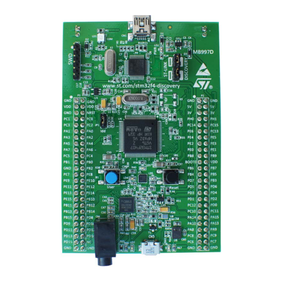
Figure 1. STM32F4DISCOVERY
.
Picture is not contractual
October 2020
UM1472 Rev 7
1/32
www.st.com
1
Advertisement
Table of Contents

Subscribe to Our Youtube Channel
Related Manuals for ST STM32F4DISCOVERY


Summary of Contents for ST STM32F4DISCOVERY
-
Page 1: Stm32F4Discovery
UM1472 User manual Discovery kit with STM32F407VG MCU Introduction The STM32F4DISCOVERY Discovery kit allows users to easily develop applications with ® ® the STM32F407VG high-performance microcontroller with the Arm Cortex -M4 32-bit core. It includes everything required either for beginners or experienced users to get started quickly. -
Page 2: Table Of Contents
Embedded ST-LINK/V2-A ........12... - Page 3 Mechanical drawing ........28 STM32F4DISCOVERY Discovery kit information ....29 Product marking .
- Page 4 List of tables UM1472 List of tables Table 1. Ordering information ............7 Table 2.
- Page 5 Figure 9. STM32F4DISCOVERY mechanical drawing ........28...
-
Page 6: Features
• Comprehensive free software including a variety of examples, part of STM32CubeF4 MCU Package, or STSW-STM32068 for using legacy standard libraries • On-board ST-LINK/V2-A debugger/programmer with USB re-enumeration capability: mass storage, Virtual COM port, and debug port • Support of a wide choice of Integrated Development Environments (IDEs) including IAR ®... -
Page 7: Ordering Information
Table 1. Ordering information Order code Board reference Target STM32 STM32F407G-DISC1 MB997 STM32F407VGT6 1. STM32F407G-DISC1 with ST-LINK/V2-A replaces the obsolete STM32F4DISCOVERY order code with ST-LINK/V2. Codification The meaning of the codification is explained in Table Table 2. Codification explanation STM32F4XXY-DISC1... -
Page 8: Development Environment
STM32 Flash memory for easy demonstration of the device peripherals in standalone mode. The latest versions of the demonstration source code and associated documentation can be downloaded from www.st.com. Conventions Table 3 provides the definition of some conventions used in the present document. -
Page 9: Quick Start
Four LEDs between buttons B1 and B2 are blinking. Press user button B1 to enable the ST MEMS sensor, move the board and observe the four LEDs blinking according to the motion direction and speed. (If a second USB cable ‘Type-A to Micro-B’... -
Page 10: Hardware And Layout
Hardware and layout UM1472 Hardware and layout The STM32F4DISCOVERY is designed around the STM32F407VGT6 microcontroller in a 100-pin LQFP package. Figure 2 illustrates the connections between the STM32F407VGT6 and its peripherals (ST- LINK/V2-A, push buttons, LEDs, audio DAC, USB, ST-MEMS accelerometer and microphone, and connectors). -
Page 11: Figure 3. Stm32F4Discovery Top Layout
UM1472 Hardware and layout Figure 3. STM32F4DISCOVERY top layout ST-LINK/V2 LD1 (red/green LED) STM32F407G-DISC1 LD2 (red LED) SWD connector MB997 ST-LINK/DISCOVERY selector www.st.com/stm32f4-discovery 5V power supply input/output DD measurement NRST 3V power supply output PC14 PC15 PC13 STM32F407VGT6 SB1 (B2-RESET) -
Page 12: Embedded St-Link/V2-A
ST-LINK solutions, refer to the Overview of ST-LINK derivatives technical note (TN1235). a. The features described in this section apply also to ST-LINK/V2, which is the debugger/programmer embedded in the obsolete Discovery kit with order code STM32F4DISCOVERY. Only Section 6.1.3: ST-... -
Page 13: Table 4. Jumper States
Activating the readout protection on an ST-LINK/V2-A target prevents the target application from running afterwards. The target readout protection must be kept disabled on ST-LINK/V2-A boards. There are two different ways to use the embedded ST-LINK/V2-A depending on the jumper states (see Table •... -
Page 14: Drivers
Before connecting the STM32F4DISCOVERY board to a Windows PC (7, 8 and 10) through the USB, a driver for the ST-LINK/V2-A must be installed. It is available at the www.st.com website. In case the STM32 Discovery board is connected to the PC before the driver is installed, some Discovery interfaces may be declared as “Unknown”... -
Page 15: St-Link/V2-A Vcp Configuration
Hardware and layout 6.1.3 ST-LINK/V2-A VCP configuration The ST-LINK/V2-A supports a Virtual COM port (VCP) on U2 pin 12 (ST-LINK_TX) and U2 pin 13 (ST-LINK_RX) but these pins are not connected to the USART of the STM32F407 microcontroller. Two solutions are possible to connect an STM32F407 USART to the VCP on the PC: •... -
Page 16: Using St-Link/V2-A To Program/Debug The Stm32F407Vg On Board
Hardware and layout UM1472 6.1.4 Using ST-LINK/V2-A to program/debug the STM32F407VG on board To program the STM32F407VG on board, simply plug in the two jumpers on CN3, as shown Figure 7 in yellow, but do not use the CN2 connector as that could disturb communication with the STM32F407VG of the STM32F4DISCOVERY. -
Page 17: Using St-Link/V2-A To Program/Debug An External Stm32 Application
Hardware and layout 6.1.5 Using ST-LINK/V2-A to program/debug an external STM32 application It is very easy to use the ST-LINK/V2-A to program the STM32 on an external application. Simply remove the two jumpers from CN3, as shown in Figure 8, and connect the... -
Page 18: Power Supply And Power Selection
5V can also be used as input power supplies, for instance when the USB connector is not connected to the PC. In this case, the STM32F4DISCOVERY board must be powered by a power supply unit or by auxiliary equipment complying with standard EN-60950-1: 2006+A11/2009, and must be Safety Extra Low Voltage (SELV) with limited power capability. -
Page 19: On-Board Audio Capability
S connection or an analog input signal. • The sound can come independently from different inputs: – ST-MEMS microphone: digital using PDM protocol or analog when using the low pass filter – USB connector: from external mass storage such as a USB key, USB HDD and others –... -
Page 20: Osc Clock
If PH0 and PH1 are used as GPIOs instead of being used as a clock, then SB13 and SB14 are closed and R24, R25 and R68 are removed. • MCO from ST-LINK. From MCO of the STM32F103. This frequency cannot be changed, it is fixed at 8 MHz and connected to PH0-OSC_IN of the STM32F407VG. Configuration needed: –... -
Page 21: Solder Bridges
6.11 Extension connectors The male headers P1 and P2 can connect the STM32F4DISCOVERY to a standard prototyping/wrapping board. The STM32F407VG GPIOs are available on these connectors. P1 and P2 can also be probed by an oscilloscope, a logical analyzer or a voltmeter. -
Page 22: Table 7. Stm32 Pin Description Versus Board Functions
Table 7. STM32 pin description versus board functions STM32 pin Board function Main Alternate LQFP Audio Audio Motion Push Free Power function functions sensor sensor button supply BOOT0 NRST RESET NRST USART2_CTS/ USART4_TX/ PA0- ETH_MII_CRS/ TIM2_CH1_ETR/ USER WKUP TIM5_CH1/ TIM8_ETR/ ADC123_IN0/ WKUP USART2_RTS/ USART4_RX/ ETH_RMII_REF_CLK/... - Page 23 Table 7. STM32 pin description versus board functions (continued) STM32 pin Board function Main Alternate LQFP Audio Audio Motion Push Free Power function functions sensor sensor button supply USART1_CTS/ CAN1_RX/ PA11 TIM1_CH4/ OTG_FS_DM USART1_RTS/ CAN1_TX/ PA12 TIM1_ETR/ OTG_FS_DP PA13 JTMS-SWDIO SWDIO PA14 JTCK-SWCLK...
- Page 24 Table 7. STM32 pin description versus board functions (continued) STM32 pin Board function Main Alternate LQFP Audio Audio Motion Push Free Power function functions sensor sensor button supply SPI2_NSS/ I2S2_WS/ TIM4_CH4/ TIM11_CH1/ OTG_FS_SDA/ SDIO_D5/ DCMI_D7/ I2C1_SDA/ CAN1_TX SPI2_SCK/ I2S2_CK/ I2C2_SCL/ USART3_TX/ OTG_HS_ULPI_D3/ PB10 ETH_MII_RX_ER/ OTG_HS_SCL/...
- Page 25 Table 7. STM32 pin description versus board functions (continued) STM32 pin Board function Main Alternate LQFP Audio Audio Motion Push Free Power function functions sensor sensor button supply ETH_RMII_RX_D0/ ETH_MII_RX_D0/ ADC12_IN14 ETH_RMII_RX_D1/ ETH_MII_RX_D1/ ADC12_IN15 I2S2_MCK/ TIM8_CH1/ SDIO_D6/ USART6_TX/ DCMI_D0/ TIM3_CH1 I2S3_MCK/ TIM8_CH2/ SDIO_D7/ MCLK USART6_RX/ DCMI_D1/ TIM3_CH2...
- Page 26 Table 7. STM32 pin description versus board functions (continued) STM32 pin Board function Main Alternate LQFP Audio Audio Motion Push Free Power function functions sensor sensor button supply FSMC_NWAIT/ USART2_RX USART2_CK/ FSMC_NE1/ FSMC_NCE2 FSMC_D13/ USART3_TX FSMC_D14/ USART3_RX PD10 FSMC_D15/ USART3_CK PD10 PD11 FSMC_A16/ USART3_CTS...
- Page 27 Table 7. STM32 pin description versus board functions (continued) STM32 pin Board function Main Alternate LQFP Audio Audio Motion Push Free Power function functions sensor sensor button supply PE14 FSMC_D11/ TIM1_CH4 PE14 PE15 FSMC_D12/ TIM1_BKIN PE15 OSC_ OSC_IN OSC_ OSC_OUT...
-
Page 28: Mechanical Drawing
Mechanical drawing UM1472 Mechanical drawing Figure 9. STM32F4DISCOVERY mechanical drawing 28/32 UM1472 Rev 7... -
Page 29: Stm32F4Discovery Discovery Kit Information
Any consequences deriving from such usage will not be at ST charge. In no event, ST will be liable for any customer usage of these engineering sample tools as reference designs or in production. -
Page 30: (Fcc) Compliance Statements30
Federal Communications Commission (FCC) and ISED Canada Compliance Statements UM1472 Appendix A Federal Communications Commission (FCC) and ISED Canada Compliance Statements FCC Compliance Statement A.1.1 Part 15.19 This device complies with Part 15 of the FCC Rules. Operation is subject to the following two conditions: (1) this device may not cause harmful interference, and (2) this device must accept any interference received, including interference that may cause undesired operation. -
Page 31: Revision History
Section 4.1 STM32F407VG microcontroller. 31-May-2017 Updated Table 6: STM32 pin description versus board functions. Removed all references to the obsolete STM32F4DISCOVERY order code and focused the ST-LINK descriptions on ST-LINK/V2-A accordingly across the document. ® Removed all mentions of Arm Mbed™. - Page 32 ST products and/or to this document at any time without notice. Purchasers should obtain the latest relevant information on ST products before placing orders. ST products are sold pursuant to ST’s terms and conditions of sale in place at the time of order acknowledgement.
Need help?
Do you have a question about the STM32F4DISCOVERY and is the answer not in the manual?
Questions and answers