Sign In
Upload
Manuals
Brands
PoolPak Manuals
Dehumidifier
PoolComPak 800
PoolPak PoolComPak 800 Dehumidifier Manuals
Manuals and User Guides for PoolPak PoolComPak 800 Dehumidifier. We have
1
PoolPak PoolComPak 800 Dehumidifier manual available for free PDF download: Engineering Manual
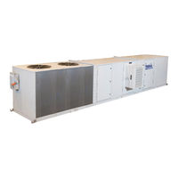
PoolPak PoolComPak 800 Engineering Manual (62 pages)
High Capacity Dehumidifier
Brand:
PoolPak
| Category:
Dehumidifier
| Size: 2 MB
Table of Contents
Table of Contents
3
Section I: Indoor Pool Design
7
Introduction
7
Creating an Ideal Environment for Indoor Pool Facilities
7
Operating Cost
7
Application
7
Moisture Loads
7
Effects of Moisture
7
Indoor Air Quality
7
Occupant Comfort
8
Pool Water Chemistry
8
Table 1-1. Typical Pool Water & Air Temperature Set-Points
8
Equipment Choices
9
Overview
9
Ventilation with Heating
9
Ventilation with Heating and Energy Recovery
9
Mechanical Dehumidification
9
Table 1-2. Recommended Pool Water Chemistry
9
Hybrids
10
Other Technologies
10
Room Air Distribution
10
Airside Design
10
Supply Air
10
Figure 1-1. Perimeter Air Distribution
11
Figure 1-2. Overhead Air Distribution
11
Figure 1-3. below Grade Air Distribution
11
Air Distribution
12
Ductwork Design
12
Figure 1-4. Supply Air Proportions
12
Return Air
12
Other Airside Considerations
13
Section II: Principles, Functions, and Features
14
The Mechanical Dehumidification System
14
Principles of Operation
14
Automatic Control of Air Temperature and Humidity
14
Room Dew Point Control
15
Poolcompak Operation
15
Figure 2-1. Poolcompak™ AW and HCD Typical Refrigerant System Schematic
15
ECC-PCP Control System
16
Overview
16
Humidity Control
16
Cold Surface Temperature Humidity Reset
16
Space Heating
16
Networking Multiple Units
17
Space Cooling (Optional)
17
Water Heating (Models AWV and AWH Only)
17
Features and Options
17
Standard Items Factory Mounted
17
Standard Items Factory Supplied for Field Installation
17
System Options
17
Roofpak System
18
Poolcompak™ Dehumidification Systems Selection
18
Available Configurations
18
Overview
18
Typical AW Series Applications
18
Typical Non-Pool HCD Series Applications
18
Unit Selection Software Program
18
Roofpak Series (HCDH/AWH)
19
Design Features
19
Durable Construction
19
Evaporator Coil Options
19
Heating Packages
19
Microprocessor Controller
19
Rooftop Installation
19
Self-Contained Air-Cooled Condensing Section
19
Cupronickel Water Heat Exchanger
20
Housed Blower
20
Totally Enclosed, Fan Cooled (TEFC) Motors
20
Unique Outside Air System
20
Technical Summary
21
Dimensional Data
21
Roofpak Weights
21
Table 2-1. Roofpak Technical Data
21
Table 2-2. Roofpak Weights
21
Figure 2-2. PCP Roofpak Dimensions
21
Section III: Performance and Sizing
22
Poolcompak™ Performance
22
Poolcompak™ AW (AWV, AWH) Performance
22
Table 3-1. Poolcompak™ AW Performance Summary
22
Poolcompak™ HCD (HCDV, HCDH) Performance
23
Table 3-2. Poolcompak™ HCD Performance Summary
23
Poolcompak Unit Dimensions
24
Figure 3-1 AW/HCD Horizontal Unit Elevation and End Views
24
Poolcompak™ Horizontal Dimensions
24
Table 3-3. AW/HCD Horizontal Unit Overall Dimensions
24
Figure 3-2. AW/HCD Vertical Unit Elevation and Plan Views
25
Poolcompak™ Vertical Dimensions
25
Table 3-4. AW/HCD Vertical Unit Overall Dimensions
25
Hot Water Coil Capacities
26
Table 3-5. Hot Water Coil Capacities
26
Poolcompak Outside Air Damper Size
27
Table 3-6. Poolcompak™ Outside Air Damper Size
27
Refrigerant
28
Table 3-7. Factory Refrigerant R410A Charge
28
Remote Air-Cooled Condenser (ACC)
29
Table 3-8. Remote ACC Performance Chart
29
Figure 3-3. Air-Cooled Condenser (Poolpak) - Isometric Views
30
Figure 3-4. Air-Cooled Condenser (Bohn) - Elevation Views
30
Electric Duct Heater
31
Table 3-9. Duct Sizes
31
Figure 3-5. Duct Heater
31
Section IV: Installation
32
PCP Installation
32
Introduction
32
Unit/Facility Interface
32
Figure 4-1. Typical Poolcompak™ AWH Series System Layout
32
Handling
33
Clearance
33
Mounting of Poolcompak Units
33
Inspection
33
Power Supply
33
Control Wiring
33
Condensate Piping
33
Curb Mounting
34
Figure 4-2. Poolcompak™ Curb Assembly
34
Integral Gas Furnace Option (Roofpak Only)
35
Table 4-1. Horizontal Poolcompak™ Curb Dimensions
35
ECC-PCP Controls Field Wiring
36
Overview
36
Remote Interface Unit (1)
36
Figure 4-3. Remote Interface Mounting Plate
36
Cold Surface Temperature Sensor (2)
37
Economizer System (Optional) (3)
37
Figure 4-4. Economizer Operation
37
Outside Air Temperature Sensor (Economizer Option Only) (4)
38
Air Cooled Condenser (Optional) (5)
38
Figure 4-5. Outside Air Sensor
38
Figure 4-6. PAC Unit Field Wiring
38
Auxiliary Pool Water Heating System (AWH Model Only*) (6)
39
Auxiliary Air Heating System (7)
39
External Alarm System (8)
39
Figure 4-7. Installation of a Hot Water Coil 3-Way Valve
39
Building Fire Control System (9)
40
Return Air Sensor (10)
40
Purge Mode Input (11)
40
AC Proof Input (12)
40
Pool Water Temperature Sensor (13)
40
Pool Water Piping (AWH and AWV Models Only*)
41
Condensate Drains
42
Figure 4-8. Typical Pool Water Piping Diagram (AWH and AWV Model Only)
42
Water Cooled Condenser
43
Remote Air-Cooled Condenser
43
Space and Location Requirements
43
Figure 4-9. AWH and HCDH Condensate Trap
43
Walls or Obstructions
43
Figure 4-10. Remote ACC Installation Around Walls or Obstructions
44
Figure 4-11. Remote ACC Installation When Installing Multiple Units
44
Figure 4-12. Remote ACC Installation When Installing Units in Pits
44
Multiple Units
44
Units in Pits
44
Decorative Fences
45
Field Installed PIPING
45
Figure 4-13. Remote ACC Installation When Installing Units Near Decorative Fences
45
Materials
45
Piping Guidelines
45
Figure 4-14. ACC Refrigerant Piping
46
Sizing
46
Refrigerant and Oil Charging
47
Sample Charging Calculation
47
Table 4-2. R410A Charge for Air Cooled Condensers (Lb.)
47
Section V: Operation
49
ECC-PCP Remote Interface Unit
49
Status Display
49
Figure 5-1. RIU Keypad
49
Figure 5-2. Status Screen 1
49
Set Point Change Menu
50
Air Temperature
50
Pool Temperature
50
Recommendations
50
Relative Humidity
50
Purge Mode Control Menu
51
Detailed Status Menu
51
ECC-PCP Network Operation
52
Network Configuration
52
Dehumidification Stage 2 Offset
52
Enable Network Control
52
Pool Water Temperature Control
52
Staged Dehumidification Control
52
Changing Set Points
53
ECC-PCP Service
53
Service Menu
53
I/O Configuration
53
Digital Inputs
53
Digital Outputs
53
Analog Inputs
54
Unit Configuration
54
Aux Air Heating
54
Aux Water Heating
54
Installed Options
54
Temperature Ctrl
54
Humidity Control
55
BAS Interface
55
Multi-Unit Network
55
Compressor
55
Economizer
55
History
55
Manual Mode
55
Utilities
55
Maintenance
56
Overview
56
Daily Maintenance
56
Monthly Maintenance
56
Annual Maintenance
56
Table 5-1. Pool Water Chemistry
56
Section VI: Wiring
57
Auxiliary Air & Pool Water Heater Connections for Multiple Unit Installation
57
Figure 6-1. Auxiliary Air and Pool Water Heater Connections for Multiple Units
57
Auxiliary Air & Pool Water Heater Connection for a Two Pool Installation
58
Figure 6-2. Auxiliary Air and Pool Water Heater Connections for Two Pool Installations
58
Field Wiring
59
Figure 6-3. Field Wiring Diagram
59
Fire Control System Connection
60
Figure 6-4. Fire Control System Connection
60
Advertisement
Advertisement
Related Products
PoolPak PoolComPak 550
PoolPak PoolComPak 1200
PoolPak PoolComPak 1400
PoolPak PoolComPak 1800
PoolPak PoolComPak 2600
PoolPak PoolComPak 3500
PoolPak PoolComPak 4000
PoolPak AW 0550
PoolPak AW 0800
PoolPak AW 1200
PoolPak Categories
Dehumidifier
Air Conditioner
Accessories
More PoolPak Manuals
Login
Sign In
OR
Sign in with Facebook
Sign in with Google
Upload manual
Upload from disk
Upload from URL