Table of Contents
Advertisement
Quick Links
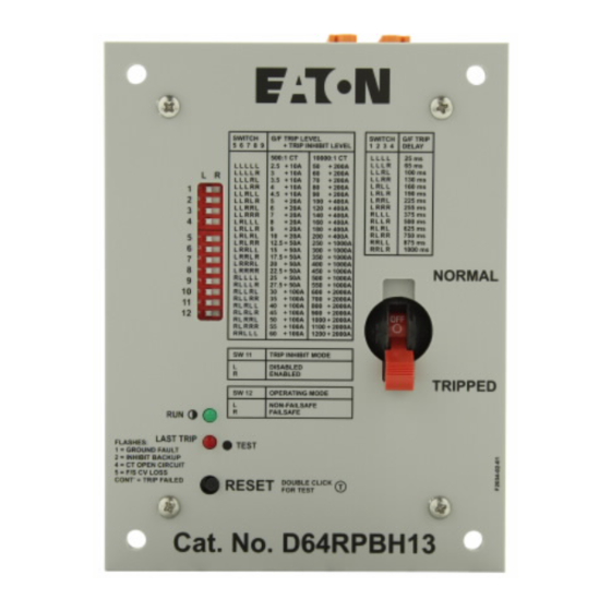
D64RPBH13 SERIES B1 GROUND FAULT RELAY
FLAS HES:
1 = GROUND FAULT
2 = INHIBIT BACKUP
4 = CT OP EN CI RCUIT
5 = F/S CV LO SS
CON T' = TRIP FAILE D
CANADA
Eaton Electrical Canadian Operation
5050 Mainway Drive
Burlington, Ontario,
L7L 5Z1
Revision 2
September, 2009
D64RPBH13 INSTRUCTION MANUAL
SWITCH
G/F TRIP LEVEL
5
6
7 8 9
+ TRIP INHIBIT LEVEL
500:1 CT
L
L
L
L
L
2.5
+
L
L
L
L
R
3
+
L R
L
L
L
R
L
3.5
+
L
L
L
R
R
4
+
1
L
L
R
L
L
4.5
+
2
L
L
R
L
R
5
+
L
L
R
R
L
6
+
3
L
L
R
R
R
7
+
4
L
R
L
L
L
8
+
L
R
L
L
R
9
+
L
R
L
R
L
10
+
5
L
R
L
R
R
12.5
+
6
L
R
R
L
L
15
+
+
L
R
R
L
R
17.5
7
L
R
R
R
L
20
+
8
+
L
R
R
R
R
22.5
R
L
L
L
L
25
+
9
R
L
L
L
R
27.5
+
10
R
L
L
R
L
30
+
R
L
L
R
R
35
+
11
R
L
R
L
L
40
+
RL
R
L
R
45
+
12
R
L
R
R
L
50
+
R
L
R
R
R
55
+
R
R
L
L
L
60
+
SW 11
TRIP INHIBIT MODE
L
DISABLED
R
ENABLED
SW 12
OPERATING MODE
L
NON-FAILSAFE
R
FAILSAFE
RUN
LAST TR IP
RESET
DOU BLE C LICK
FOR TE ST
Cat. No. D64RPBH13
Page 1
SWITCH
G/F TRIP
1 2 3 4
DELAY
10000:1 CT
L
L
L
L
25 ms
L
L
L
R
65 ms
10A
50
+
200A
L
L
R
L
100 ms
10A
60
+
200A
L
L
R
R
130 ms
10A
70
+
200A
L
R
L
L
160 ms
10A
80
+
200A
L
R
L
R
190 ms
10A
90
+
200A
L
R
R
L
225 ms
20A
100
+
400A
L
R
R
R
255 ms
20A
120
+
400A
R
L
L
L
375 ms
20A
140
+
400A
R
L
L
R
500 ms
20A
160
+
400A
R
L
R
L
625 ms
20A
180
+
400A
R
L
R
R
750 ms
20A
200
+
400A
R
R
L
L
875 ms
50A
250
+
1000A
R
R
L
R
1000 ms
50A
300
+
1000A
50A
350
+
1000A
50A
400
+
1000A
50A
NORMAL
450
+
1000A
50A
500
+
1000A
50A
550
+
1000A
100A
600
+
2000A
100A
700
+
2000A
100A
800
+
2000A
100A
900
+
2000A
100A
1000
+
2000A
100A
1100
+
2000A
100A
1200
+
2000A
TRIPPED
T
USA
Eaton Electrical
1000 Cherrington Parkway
Moon Township, PA
15108
PUB 50413
Advertisement
Table of Contents

Related Manuals for Eaton Cutler-Hammer D64 Series


Summary of Contents for Eaton Cutler-Hammer D64 Series
- Page 1 5 = F/S CV LO SS RESET DOU BLE C LICK CON T’ = TRIP FAILE D FOR TE ST Cat. No. D64RPBH13 CANADA Eaton Electrical Canadian Operation Eaton Electrical 5050 Mainway Drive 1000 Cherrington Parkway Burlington, Ontario, Moon Township, PA L7L 5Z1...
-
Page 2: Table Of Contents
PUB 50413 D64RPBH13 SERIES B1 GROUND FAULT RELAY TABLE OF CONTENTS PAGE TABLE OF CONTENTS ......................... LIST OF FIGURES, TABLES & FORMS ....................GENERAL DESCRIPTION ......................OPERATION ......................... GLOSSARY OF TERMS ....................DIPSWITCH SETTINGS ....................2.2.1 GROUND FAULT TRIP DELAY ............... 2.2.2 GROUND FAULT TRIP LEVEL ............... -
Page 3: General Description
DC current sent through the secondary windings of a CT can bias its core enough to shift the trip point outside specification on sensitive settings. For the CT supervision to work, either the special Eaton’s Cutler- Hammer C311CT zero sequence current transformer with a turns ratio of 10000:1, or the standard family of Series A2 C311CT zero sequence current transformers with a turns ratio of 500:1 must be installed, as specified in section 3.2. -
Page 4: Operation
PUB 50413 D64RPBH13 SERIES B1 GROUND FAULT RELAY Pull-apart terminal blocks simplify connection of field wiring. They have two 12 AWG screw clamps per pole with 90° and 180° orientation. Captive screws secure the blocks to the relay, safe from the effects of shock and vibration. -
Page 5: Dipswitch Settings
200 Amps to 2000 amps when using the special Eaton’s Cutler-Hammer C311CT zero sequence current transformer with a turns ratio of 10000:1. With Inhibit Enabled, if the ground fault current exceeds the inhibit level the output circuit breaker will be inhibited until the ground fault current drops below the inhibit level. -
Page 6: Ground Fault Trip Delay
2.2.2 GROUND FAULT TRIP LEVEL The ground fault TRIP LEVEL range is either 50 - 1200 Amps when using the special Eaton’s Cutler- Hammer C311CT zero sequence current transformer with a turns ratio of 10000:1 or 2.5 – 60 Amps when using the standard family of C311CT zero sequence current transformers with a turns ratio of 500:1. -
Page 7: Trip Inhibit Mode
PUB 50413 D64RPBH13 SERIES B1 GROUND FAULT RELAY Table 2: Ground Fault Trip Level DIPSWITCH LEVELS WHEN USING C311CTs LEVELS WHEN USING C311CTs SETTINGS WITH 500:1 TURNS RATIO WITH 10,000:1 TURNS RATIO TRIP LEVEL INHIBIT LEVEL TRIP LEVEL INHIBIT LEVEL IN AMPS IN AMPS IN AMPS... -
Page 8: Output Circuit Breaker Operating Mode
PUB 50413 D64RPBH13 SERIES B1 GROUND FAULT RELAY 2.2.4 OUTPUT CIRCUIT BREAKER OPERATING MODE –CONTACT STATE The two different OPERATING MODES are described under the glossary of terms. The setting of DIPswitch 12 determines the operating mode of the D64RPBH13 output circuit breaker. This is shown in Table 4. -
Page 9: G/F Test - Reset
PUB 50413 D64RPBH13 SERIES B1 GROUND FAULT RELAY Two .25 s flashes every few seconds means that the ground fault current exceeded the Trip Inhibit Level but the upstream device failed to trip during 1.2 s. The D64RPBH13 then tripped as a last resort. The contactor should be replaced since its contacts may well be damaged. -
Page 10: Memory After Loss Of Control Voltage
PUB 50413 D64RPBH13 SERIES B1 GROUND FAULT RELAY MEMORY AFTER LOSS OF CONTROL VOLTAGE When control voltage is removed from the D64RPBH13, the LAST TRIP registration will be memorized (for at least one week). Pressing the Reset pushbutton before restoring control voltage will light either the green LED or the red LED, green indicating no trip was registered and red indicating the opposite. -
Page 11: External C311Ct Current Transformer
D64RPBH13 SERIES B1 GROUND FAULT RELAY EXTERNAL C311CT CURRENT TRANSFORMER The D64RPBH13 is designed to operate with either, a special Eaton’s Cutler-Hammer C311CT zero sequence current transformer with a turns ratio of 10000:1 or, the standard family of C311CT zero sequence current transformers with a turns ratio of 500:1. -
Page 12: Catalog Numbers
For mounting dimensions and additional information on C311CT current transformers refer to the current Eaton’s Cutler-Hammer catalog. The D64RPBH13 is designed to operate with special Eaton’s Cutler-Hammer C311CT current transformers having a turns ratio of 10,000:1. Each C311CT is epoxy molded for exceptional mechanical properties and has a high-grade silicon iron core for excellent coupling characteristics. - Page 13 PUB 50413 D64RPBH13 SERIES B1 GROUND FAULT RELAY Output Circuit breaker: Contacts: Maximum UL rating: ............... 3 A @ 250 V ac, resistive EN 60947-5-1 rating: ......1 A @ 125 Vac, Utilization category AC-12 Maximum fusing under EN 60947-5-1: ............10 A Endurance: ..............Greater than 10,000 operations Dielectric strength ................
- Page 14 PUB 50413 D64RPBH13 SERIES B1 GROUND FAULT RELAY Current Transformer ..........either C311CT current transformer with 500:1 ratio or, special C311CT current transformer 10,000:1 ratio Thermal Characteristics when using C311CT current transformer with 500:1 ratio: Short Time Withstand: 1000A ......................1 second 2000A ......................
- Page 15 PUB 50413 D64RPBH13 SERIES B1 GROUND FAULT RELAY EN 61000-4-11 Electromagnetic compatibility (EMC) for industrial-process measurement and control equipment – Part 4-11: Voltage dips/drops/variations immunity EN 60947-5-1 Low-voltage switchgear and controlgear – Part 5-1: Control circuit devices and switching elements – Electromechanical control circuit devices UL 1053 Ground-Fault Sensing and Relaying Equipment, Class 1 UL File E195341 C22.2 No.
-
Page 16: Typical Field Connections
PUB 50413 D64RPBH13 SERIES B1 GROUND FAULT RELAY FIGURE 1 - TYPICAL FIELD CONNECTION GROUNDED SYSTEMS POWER SOURCE - 1 Phase 2 wire - 1 Phase 3 wire - 3 Phase 3 wire - 3 Phase 4 wire CURRENT CARRYING NEUTRAL, WHEN USED CB COIL... -
Page 17: Dimensions & Weights
PUB 50413 D64RPBH13 SERIES B1 GROUND FAULT RELAY FIGURE 2 - DIMENSIONS AND WEIGHTS 2.36" (60) 0.20" 1.38" 0.65" (35) (16.6) 0.30" (7.5) DIN Rail Release 4.92" 3.35" (125) (85) 3.94" 3.94" (100) (100) Mounting hole Dia 0.22” (5.5) 35 mm DIN RAIL 3.94"... -
Page 18: Circuit Breaker Trip Contact States
PUB 50413 D64RPBH13 SERIES B1 GROUND FAULT RELAY TABLE 1 – CIRCUIT BREAKER TRIP CONTACT STATES STATE OF CIRCUIT BREAKER TRIP CONTACTS UNDER VARIOUS OPERATING CONDITIONS WITH DIPSWITCH 12 IN SELECTED POSITIONS DIPSWITCH 12 IN LEFT POSITION DIPSWITCH 12 IN RIGHT POSITION NON-FAILSAFE MODE FAILSAFE MODE NON-FAILSAFE... -
Page 19: Test Record
PUB 50413 D64RPBH13 SERIES B1 GROUND FAULT RELAY FORM 1 - TEST RECORD GROUND FAULT TEST – D64RPBH13 G/F TEST INTERNAL Double-clicking the built-in RESET – TEST pushbutton invokes a test which switches an AC voltage onto the processor’s CT sensor input. The voltage is scaled to simulate a Ground fault current of 1.5 times the G/F trip level set point.
Need help?
Do you have a question about the Cutler-Hammer D64 Series and is the answer not in the manual?
Questions and answers