Table of Contents
Advertisement
Quick Links
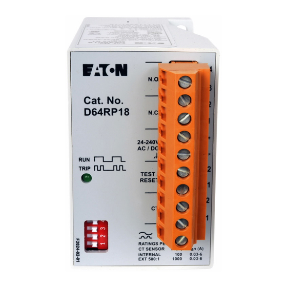
D64RP18 SERIES B1 DIGITAL GROUND FAULT RELAY
CANADA
Eaton Electrical Canadian Operation
3228 South Service Road
Burlington, Ontario,
L7R 3Y8
Revision 2
May, 2005
D64RP18 INSTRUCTION MANUAL
N.O.
N.C.
24-240V
AC/DC
TEST/
RESET
CT
RATINGS PER IEC 60755
CT SENSOR
In (A)
INTERNAL
100
EXT 500:1
1000
Page 1
N.O. CONTROL CIRCUIT
N.C. CONTROL CIRCUIT
L
POWER SUPPLY
N
TEST/RESET PUSHBUTTON
EXTERNAL CORE BALANCE CT
I n (A)
0.03-6.
0.03-6.0
U.S.A
Eaton Electrical
4201 North 27th Street
Milwaukee, WI
53216
PUB 50411
Advertisement
Table of Contents

Related Manuals for Eaton Cutler-Hammer D64RP18


Summary of Contents for Eaton Cutler-Hammer D64RP18
- Page 1 CT SENSOR In (A) I n (A) INTERNAL 0.03-6. EXT 500:1 1000 0.03-6.0 CANADA U.S.A Eaton Electrical Canadian Operation Eaton Electrical 3228 South Service Road 4201 North 27th Street Burlington, Ontario, Milwaukee, WI L7R 3Y8 53216 Revision 2 May, 2005...
-
Page 2: Table Of Contents
PUB 50411 D64RP18 SERIES B1 DIGITAL GROUND FAULT RELAY TABLE OF CONTENTS PAGE TABLE OF CONTENTS ......................... LIST OF TABLES, FIGURES & FORMS....................GENERAL DESCRIPTION......................OPERATION ......................... GLOSSARY OF TERMS....................DIPSWITCH SETTINGS....................2.2.1 GROUND FAULT TRIP CURRENT LEVEL ............. 2.2.2 GROUND FAULT TRIP DELAY TIME ............. -
Page 3: General Description
660 Volts is the maximum system operating voltage for the D64RP18 when passing the system power conductors through the built-in CT. However, by using any Eaton’s Cutler-Hammer C311CT zero sequence current transformers with 500:1 ratio, connecting the secondary to terminals T1 and T2 of the relay, and passing the system insulated power conductors through the window of this CT, the D64RP18 can be applied on any system voltage. - Page 4 PUB 50411 D64RP18 SERIES B1 DIGITAL GROUND FAULT RELAY Pulsed (Trip) Auto Reset: Each time control power is applied, the internal processor of the D64RP18 selects this mode when it sees a closed circuit on terminals R1 & R2 (there is a jumper or a N.C. pushbutton connected to R1 and R2).
-
Page 5: Dipswitch Settings
The system primary phase current on which the D64RP18 is being applied exceeds 100 Amps continuous. Any Eaton’s Cutler-Hammer C311CT with 500:1 ratio may be used when the above requirements dictate the use of an external CT. The ground fault trip current setting range of 30 mA –... -
Page 6: Ground Fault Trip Current Level
PUB 50411 D64RP18 SERIES B1 DIGITAL GROUND FAULT RELAY TABLE 1 – DIPSWITCH SETTINGS In the table below ‘R’ denotes right and ‘L’ denotes left. Switch Function Set to Meaning 1 2 3 Ground fault trip current limit R L L 30 mA R L R 120 mA... -
Page 7: Output Relay Contact State
PUB 50411 D64RP18 SERIES B1 DIGITAL GROUND FAULT RELAY OUTPUT RELAY CONTACT STATE The output relay contact state is determined by the operating mode selected and the sensing condition of the D64RP18 relay. This is shown in Table 2. Use this table when deciding on field connections. Refer to the CONNECTIONS section. -
Page 8: Built-In Current Transformer
Refer to the Glossary of Terms to determine if an external Current Transformer is required for the application. The D64RP18 will work with Eaton’s Cutler-Hammer C311CT current transformers having a turns ratio of 500:1. These are epoxy molded to give exceptional mechanical properties and have high-grade silicon iron cores for excellent coupling characteristics. -
Page 9: Connecting More Than One D64Rp18 To Remote Test/Reset
PUB 50411 D64RP18 SERIES B1 DIGITAL GROUND FAULT RELAY The terminals are pull apart. If an external CT is being used, connect the two secondary terminals of the CT to terminals T1 and T2 of the relay using 14 AWG (minimum). Twist the leads to optimise electromagnetic immunity. Note: The CT’s input terminals T1 and T2 are NOT isolated from the control voltage. -
Page 10: Technical Specifications
C311CT4 Split core zero sequence current transformer, 4" x 13.8" window For mounting dimensions and additional information on C311CT current transformers refer to the current Eaton’s Cutler-Hammer catalog. TECHNICAL SPECIFICATION Control Voltage (non-isolated)................24 – 240 Volts ac or dc Power consumption ............ - Page 11 PUB 50411 D64RP18 SERIES B1 DIGITAL GROUND FAULT RELAY A simulated current equal to 120% of the trip current set on the Trip Level DIPswitches replaces the measured current. This tests all internal electronics and secondary winding of the built-in current transformer. No external power supply or additional wiring is required. Remote Test ............
- Page 12 C22.2 No. 144-M91 Ground Fault Circuit Interrupters CSA File 700103 CE mark – Declaration of Conformity External Current Transformer (when required) Use Eaton’s Cutler-Hammer C311CT series with 500:1 ratio, listed in section 4 – Catalog Numbers. Revision 2 May, 2005...
-
Page 13: Output Relay Contact States
PUB 50411 D64RP18 SERIES B1 DIGITAL GROUND FAULT RELAY TABLE 2 – OUTPUT CONTACT STATES STATE OF OUTPUT RELAY CONTACTS UNDER VARIOUS OPERATING CONDITIONS WITH OPEN OR CLOSED CONTACTS CONNECTED TO TERMINALS R1 AND R2 OPERATING NON-FAILSAFE PULSED AUTO RESET Open Contacts on Terminals Closed Contacts on Terminals CONDITIONS... -
Page 14: Typical Field Connection With Built-In Ct
PUB 50411 D64RP18 SERIES B1 DIGITAL GROUND FAULT RELAY POWER SOURCE GROUNDED SYSTEMS - 1 Phase 2 wire - 1 Phase 3 wire - 3 Phase 3 wire - 3 Phase 4 wire CURRENT CARRYING NEUTRAL, WHEN USED TRIP START STOP N.O. -
Page 15: Typical Field Connection With 500:1 Interposing Ct
PUB 50411 D64RP18 SERIES B1 DIGITAL GROUND FAULT RELAY POWER SOURCE GROUNDED SYSTEMS - 1 Phase 2 wire - 1 Phase 3 wire - 3 Phase 3 wire - 3 Phase 4 wire CURRENT CARRYING NEUTRAL, WHEN USED N.O. N.C. 24-240V AC/DC “DOUBLE CLICK FOR TEST”... -
Page 16: Dimensions And Weights D64Rp18 Relay
PUB 50411 D64RP18 SERIES B1 DIGITAL GROUND FAULT RELAY FIGURE 3 - DIMENSIONS AND WEIGHTS D64RP18 2.76 (70) 1.77 (45) 1.38 (35) Mounting 1.10 (28) hole Dia 0.22“ (5.5) 35 mm DIN RAIL DIN Rail 1.26 (32) Release REAR PANEL MOUNTING RIGHT HAND SIDE VIEW DIN RAIL OR 2 SCREW OPEN WEIGHT: 0.88 LBS. -
Page 17: Test Record
PUB 50411 D64RP18 SERIES B1 DIGITAL GROUND FAULT RELAY FORM 1 - TEST RECORD GROUND FAULT TEST – D64RP18 Double clicking the remote button connected to terminals R1 and R2 invokes a relay test. A simulated current equal to 1.2 times the trip current set on the Trip Level DIPswitches replaces the measured current.
Need help?
Do you have a question about the Cutler-Hammer D64RP18 and is the answer not in the manual?
Questions and answers