Table of Contents
Advertisement
Quick Links
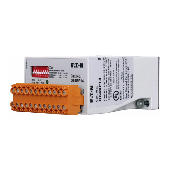
D64RP14 SERIES A2 DIGITAL GROUND FAULT RELAY
REMOTE
VOLTMETER
EXTERNAL CORE
BALANCE CT
CANADA
Eaton Electrical Canadian Operation
3228 South Service Road
Burlington, Ontario,
L7R 3Y8
Revision 1
May, 2005
D64RP14 INSTRUCTION MANUAL
RATINGS PER IEC 60755
CT SENSOR
INTERNAL
EXT 500:1
TEST/
24-240V
METER
CT
RESET
AC/DC
Wires
M+ M-
T1
T2
R1 R2 N- L+
TEST/RESET
PUSHBUTTON
Page 1
In (A)
I n (A)
100
0.5-10
1000
0.5-10
N.C.
N.O.
11 12 13 14
N.O. CONTROL
N.C. CONTROL
CIRCUIT
L
POWER
SUPPLY
N
U.S.A
Eaton Electrical
4201 North 27th Street
Milwaukee, WI
53216
PUB 51079
CIRCUIT
Advertisement
Table of Contents

Related Manuals for Eaton Cutler-Hammer D64RP14 Series


Summary of Contents for Eaton Cutler-Hammer D64RP14 Series
- Page 1 N.C. CONTROL EXTERNAL CORE CIRCUIT BALANCE CT TEST/RESET POWER PUSHBUTTON SUPPLY CANADA U.S.A Eaton Electrical Canadian Operation Eaton Electrical 3228 South Service Road 4201 North 27th Street Burlington, Ontario, Milwaukee, WI L7R 3Y8 53216 Revision 1 May, 2005 Page 1...
-
Page 2: Table Of Contents
PUB 51079 D64RP14 SERIES A2 DIGITAL GROUND FAULT RELAY TABLE OF CONTENTS PAGE TABLE OF CONTENTS ......................... LIST OF TABLES, FIGURES & FORMS....................GENERAL DESCRIPTION......................OPERATION ......................... GLOSSARY OF TERMS....................DIPSWITCH SETTINGS....................2.2.1 GROUND FAULT TRIP CURRENT LEVEL ............. 2.2.2 GROUND FAULT TRIP DELAY TIME ............. -
Page 3: General Description
660 Volts is the maximum system operating voltage for the D64RP14 when passing the system power conductors through the built-in CT. However, by using any Eaton’s Cutler-Hammer C311CT zero sequence current transformers with 500:1 ratio, connecting the secondary to terminals T1 and T2 of the relay, and passing the system insulated power conductors through the window of this CT, the D64RP14 can be applied on any system voltage. -
Page 4: Operation
PUB 51079 D64RP14 SERIES A2 DIGITAL GROUND FAULT RELAY OPERATION GLOSSARY OF TERMS Manual Reset: A N.O. contact remote RESET pushbutton connected to terminals R1 and R2 of the D64RP14 must be pressed once to reset the output relay after a trip, providing the ground fault has been cleared or the measured values are within the preset limits. - Page 5 The system primary phase current on which the D64RP14 is being applied exceeds 100 Amps continuous. Any Eaton’s Cutler-Hammer C311CT with 500:1 ratio may be used when the above requirements dictate the use of an external CT. The ground fault trip current setting range of 1 Amp –...
-
Page 6: Dipswitch Settings
PUB 51079 D64RP14 SERIES A2 DIGITAL GROUND FAULT RELAY The two secondary terminals of the external CT are to be connected to terminals T1 and T2 of the D64RP14. Chassis Ground Chassis ground is the ground to which all of the non-current carrying metal equipment is connected/bonded. -
Page 7: Ground Fault Trip Delay Time
PUB 51079 D64RP14 SERIES A2 DIGITAL GROUND FAULT RELAY As indicated in the General Description, it is recommended that the ground fault TRIP LEVEL setting be kept as close to the charging current as possible. This will provide maximum safety for operating personnel and equipment protection. -
Page 8: Installation Instructions
PUB 51079 D64RP14 SERIES A2 DIGITAL GROUND FAULT RELAY After the trip, if the relay operating mode is Non-Failsafe or Failsafe, the output relay will remain tripped and the green LED will fast blink until the button is pressed (Manual Reset) After the trip, if the relay operating mode is Pulsed Trip Auto Reset, the output relay will reset and the green LED will revert to slow flash 3 second after the test was invoked (Auto Reset) A “Test Record Form”... -
Page 9: Connections
PUB 51079 D64RP14 SERIES A2 DIGITAL GROUND FAULT RELAY The D64RP14 will work with Eaton’s Cutler-Hammer C311CT current transformers having a turns ratio of 500:1. These are epoxy molded to give exceptional mechanical properties and have high-grade silicon iron cores for excellent coupling characteristics. -
Page 10: Connecting More Than One D64Rp14 To Remote Test/Reset
PUB 51079 D64RP14 SERIES A2 DIGITAL GROUND FAULT RELAY Figure 1 shows the D64RP14 using its built-in current transformer in conjunction with a NGR and a typical connection of a circuit breaker with a shunt trip coil (ST). Pulsed Trip Auto Reset operating mode has been selected. - Page 11 PUB 51079 D64RP14 SERIES A2 DIGITAL GROUND FAULT RELAY Output Relay: Contacts: Maximum UL rating: 5 A @ 250 Vac, general use 5 A @ 30 Vdc, resistive 1/8 hp, 250 Vac 2 A, 250 VA, @ 125 Vac, pilot duty 1 A, 250 VA, @ 250 Vac, pilot duty 0.88 A, 26.4 VA, @ 30 Vdc, pilot duty EN 60947-5-1 rating:...
- Page 12 PUB 51079 D64RP14 SERIES A2 DIGITAL GROUND FAULT RELAY Ground Fault Trip Time Delay.................0.5 –10.0 seconds Setting within Range ............DIPswitches 4, 5, & 6 on front of relay Accuracy: Has a current dependent behavior: If set for Delay when current exceeds trip current setting by a factor of ≥6 0.5 sec 546-579 ms...
- Page 13 C22.2 No. 144-M91 Ground Fault Circuit Interrupters CSA File 700103 CE mark – Declaration of Conformity External Current Transformer (when required) Use Eaton’s Cutler-Hammer C311CT series with 500:1 ratio, listed in section 4 – Catalog Numbers. Revision 1 May, 2005...
-
Page 14: Output Relay Contact States
PUB 51079 D64RP14 SERIES A2 DIGITAL GROUND FAULT RELAY TABLE 2 – OUTPUT CONTACT STATES STATE OF OUTPUT RELAY CONTACTS UNDER VARIOUS OPERATING CONDITIONS WITH DIPSWITCHES 7 & 8 IN SELECTED POSITIONS OPERATING NON-FAILSAFE FAILSAFE PULSED AUTO RESET CONDITIONS 7-Down, 8-Down 7-Down, 8-Up 7-Up, 8-Down 1.CONTROL POWER OFF... -
Page 15: Typical Field Connection With Built-In Ct
PUB 51079 D64RP14 SERIES A2 DIGITAL GROUND FAULT RELAY C.B. POWER SOURCE 0-10V VOLTMETER WITH 0-100% SCALE RATINGS PER IEC 60755 CT SENSOR In (A) I n (A) INTERNAL 0.5-10 EXT 500:1 1000 0.5-10 TEST/ 24-240V METER RESET AC/DC N.C. N.O. -
Page 16: Typical Field Connection With 500:1 Interposing Ct
PUB 51079 D64RP14 SERIES A2 DIGITAL GROUND FAULT RELAY POWER SOURCE GROUNDED SYSTEMS - 1 Phase 2 wire - 1 Phase 3 wire - 3 Phase 3 wire - 3 Phase 4 wire CURRENT CARRYING NEUTRAL, WHEN USED START STOP RATINGS PER IEC 60755 TRIP CT S ENSOR... -
Page 17: Dimensions And Weights D64Rp14 Relay
PUB 51079 D64RP14 SERIES A2 DIGITAL GROUND FAULT RELAY FIGURE 3 - DIMENSIONS AND WEIGHTS D64RP14 2.76 (70) 2,76 (70) 2.36 (60) 1.10 (28) Mounting hole Dia 0.22“ (5.5) 35 mm DIN-rail 2 DIN-rail clips 1.26 (32) DIN-rail 2 DIN-rail clips REAR PANEL MOUNTING BOTTOM SIDE VIEW... -
Page 18: Test Record
PUB 51079 D64RP14 SERIES A2 DIGITAL GROUND FAULT RELAY FORM 1 - TEST RECORD GROUND FAULT TEST – D64RP14 Double clicking the remote button connected to terminals R1 and R2 invokes a relay test. A simulated current equal to 1.2 times the trip current set on the Trip Level DIPswitches replaces the measured current.
Need help?
Do you have a question about the Cutler-Hammer D64RP14 Series and is the answer not in the manual?
Questions and answers