Table of Contents
Advertisement
Quick Links
D64RPB100 SERIES B1 DIGITAL GROUND FAULT RELAY
CANADA
Eaton Electrical Canadian Operation
5050 Mainway Drive
Burlington, Ontario,
L7L 5Z1
Revision 3
April, 2008
D64RPB100 INSTRUCTION MANUAL
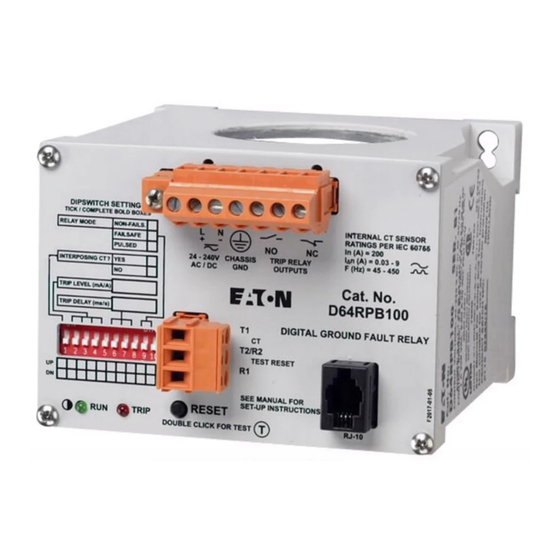
DIPSWITCH SETTINGS
TICK / COMPLETE BOLD BOXES
1
2
3
RELAY MODE
NON-FAILS.
L
N
-
+
FAILSAFE
PULSED
24 - 240V
CHASSIS
AC / DC
GND
INTERPOSING CT?
YES
NO
TRIP LEVEL (mA/A)
TRIP DELAY (ms/s)
T1
T2/R2
UP
R1
DN
SEE MANUAL FOR
SET-UP INSTRUCTIONS
RESET
RUN
TRIP
DOUBLE CLICK FOR TEST
A
kA
G/F
TRIP
RUN
VERIFY
DIGITAL
DISPLAY
D64D1
TEST
RESET
HOLD RESET AND PRESS TEST TO INVOKE TEST
Page 1
14
13
12
11
INTERNAL CT SENSOR
RATINGS PER IEC 60755
NO
NC
In (A)= 200
I n (A)= 0.03-9
TRIP RELAY
∆
OUTPUTS
DIGITAL GROUND FAULT RELAY
D64RPB100
CT
TEST RESET
T
RJ-10
USA
Eaton Electrical
1000 Cherrington Parkway
Moon Township, PA
15108
PUB 50412
Advertisement
Table of Contents

Related Manuals for Eaton Cutler-Hammer D64RPB100 Series


Summary of Contents for Eaton Cutler-Hammer D64RPB100 Series
- Page 1 TRIP VERIFY DIGITAL DISPLAY D64D1 TEST RESET HOLD RESET AND PRESS TEST TO INVOKE TEST CANADA Eaton Electrical Canadian Operation Eaton Electrical 5050 Mainway Drive 1000 Cherrington Parkway Burlington, Ontario, Moon Township, PA L7L 5Z1 15108 Revision 3 April, 2008...
-
Page 2: Table Of Contents
PUB 50412 D64RPB100 SERIES B1 DIGITAL GROUND FAULT RELAY TABLE OF CONTENTS PAGE TABLE OF CONTENTS ......................... LIST OF TABLES, FIGURES & FORMS....................GENERAL DESCRIPTION......................OPERATION ......................... GLOSSARY OF TERMS....................DIPSWITCH SETTINGS....................2.2.1 CT CONFIGURATION..................2.2.2 GROUND FAULT TRIP CURRENT LEVEL ............. 2.2.3 GROUND FAULT TRIP DELAY TIME ............. -
Page 3: General Description
660 Volts is the maximum system operating voltage for the D64RPB100 when passing the system power conductors through the built-in CT. However, by using any Eaton’s Cutler-Hammer C311CT 500:1 ratio CT and connecting the secondary to CT input terminals T1 & T2 or, by using any suitably rated, commercially available, interposing CT with 5 Amp secondary, and passing the secondary lead through the built-in CT, the relay can be used on any system voltage. -
Page 4: Operation
PUB 50412 D64RPB100 SERIES B1 DIGITAL GROUND FAULT RELAY OPERATION GLOSSARY OF TERMS Manual Reset: The RESET pushbutton on the front of the D64RPB100 or, the remote TEST/RESET pushbutton connected to terminals R1 & R2, must be pressed once to reset the output relay after a trip, providing the ground fault has been cleared or the measured values are within the preset limits. - Page 5 The system primary phase current on which the D64RPB100 is being applied exceeds 200 Amps continuous. Any Eaton’s Cutler-Hammer C311CT with 500:1 ratio may be used when the above requirements dictate the use of an external CT. The ground fault trip current setting range of 30 mA –...
-
Page 6: Dipswitch Settings
PUB 50412 D64RPB100 SERIES B1 DIGITAL GROUND FAULT RELAY Interposing Current Transformer A Current Transformer with the 5 Amp secondary of the CT passing through the window of the built-in CT of the D64RPB100. Interposing current transformers (CTs) are required on applications where: The ground fault trip current setting levels are higher than the 30 mA –9 Amp range available with the built-in 1.81”... -
Page 7: Ground Fault Trip Current Level
PUB 50412 D64RPB100 SERIES B1 DIGITAL GROUND FAULT RELAY 3.0 – 900 Amps by passing the 5 Amp secondary of an interposing CT with a windings ratio of 500:5 through the built-in 1.81” CT. 30 – 9000 Amps by passing the 5 Amp secondary of an interposing CT with a windings ratio of 5000:5 through the built-in 1.81”... -
Page 8: Indication
PUB 50412 D64RPB100 SERIES B1 DIGITAL GROUND FAULT RELAY INDICATION There are two LED’s on the front of the D64RPB100. Green RUN LED Flashing: Okay Off: No control voltage or D64RPB100 defective Steady on: Control voltage too low or D64RPB100 defective Red TRIP LED Off: No trip... -
Page 9: Built-In Current Transformer
Refer to the Glossary of Terms to determine if an external Current Transformer is required for the application. The D64RPB100 will work with Eaton’s Cutler-Hammer C311CT current transformers having a turns ratio of 500:1. These are epoxy molded to give exceptional mechanical properties and have high-grade silicon iron cores for excellent coupling characteristics. -
Page 10: Connections
PUB 50412 D64RPB100 SERIES B1 DIGITAL GROUND FAULT RELAY Verify that the polarity of the conductors is correct when they pass through the CT. Verify that ground paths do not exist that would bypass the CT. Position power cables in the center of the current transformer opening. Keep cables and buswork clear of the split on split core current transformers. -
Page 11: Connecting More Than One D64Rpb100 To Remote Test/Reset
PUB 50412 D64RPB100 SERIES B1 DIGITAL GROUND FAULT RELAY Either side of the secondary circuit on the interposing CT may be grounded where required by electrical regulations. This ground connection should be made to the same grounding point as terminal 3 of the D64RPB100. This will avoid ground loops and nuisance tripping. 3.5.1 CONNECTING MORE THAN ONE D64RPB100 TO REMOTE TEST/RESET Up to 25 D64RPB100 relays in the same enclosure may share a common remote Test/Reset... -
Page 12: D64D2 Remote Indicator Unit
PUB 50412 D64RPB100 SERIES B1 DIGITAL GROUND FAULT RELAY 2 blank boxes to the right of the LCD display window are marked “A” and “kA”. Use a permanent marker to check the appropriate box as follows: “A” – when using the built-in CT, a 500:1 ratio C311CT external CT, or a 500:5 ratio interposing “kA”... -
Page 13: Technical Specifications
C311CT28 1.1” (28 mm) inside diameter, Toroidal – with wire leads For mounting dimensions and additional information on C311CT current transformers refer to the current Eaton’s Cutler-Hammer catalog. TECHNICAL SPECIFICATION Control Voltage..................... 24 – 240 Volts ac or dc 0.6 VA @ 24 Vac 0.8 VA @ 120 Vac... - Page 14 PUB 50412 D64RPB100 SERIES B1 DIGITAL GROUND FAULT RELAY Output Relay (cont’d): Contacts: EN 60947-5-1 rating: 5 A @ 30 Vdc, Utilization category DC-12 3 A @ 24 Vdc, Utilization category DC-13 Maximum fusing under EN 60947-5-1: ............13 A Isolation voltage ............
- Page 15 PUB 50412 D64RPB100 SERIES B1 DIGITAL GROUND FAULT RELAY Ground Fault Trip Time Delay Accuracy (cont’d): Trip Current Level set at 4 Amps (400 A, 4 kA) @ ≥ ≥ ≥ ≥ 3.7 x Ground Trip delay @ 1.2 x Ground @ 2 x Ground setpoint Fault setpoint...
- Page 16 PUB 50412 D64RPB100 SERIES B1 DIGITAL GROUND FAULT RELAY Ground Fault Trip Current Level 30 mA - 9000 Amps in three ranges Sensing Ranges Vs Trip Current Level Settings: 10 mA – 10 Amp with built-in CT ............30 mA – 9 Amp 10 mA –...
- Page 17 PUB 50412 D64RPB100 SERIES B1 DIGITAL GROUND FAULT RELAY Applicable Standards: EN 61000-6-3 Electromagnetic compatibility (EMC) - Part 6-3 Generic standards– Emission standard for residential, commercial and light-industrial environments (note: = lowest levels): 30-230 MHz 30 dBµV at 10m distance 230-1000 MHz 37 dBµV at 10m distance EN 61000-6-2...
- Page 18 Open......................0.4 lbs. (0.18 kg) Packaged ....................0.95 lbs. (0.43 kg) External Current Transformer (when required) Use Eaton’s Cutler-Hammer C311CT series with 500:1 ratio, listed in section 5 – Catalog Numbers. Interposing Current Transformer (when required) Ratio for 1 – 1000 Amp sensing range ................500:5 Ratio for 10 –...
-
Page 19: Dipswitch Settings
PUB 50412 D64RPB100 SERIES B1 DIGITAL GROUND FAULT RELAY TABLE 1 – DIPSWITCH SETTINGS In the table below ‘D’ denotes down and ‘U’ denotes up. Switch Function Set to Meaning CT configuration No interposing CT, With 500:1External CT, or With 5000:5 interposing CT With 500:5 interposing CT 2 3 4 5... -
Page 20: Output Relay Contact States
PUB 50412 D64RPB100 SERIES B1 DIGITAL GROUND FAULT RELAY TABLE 2 – OUTPUT CONTACT STATES STATE OF OUTPUT RELAY CONTACTS UNDER VARIOUS OPERATING CONDITIONS WITH DIPSWITCHES 9 & 10 IN SELECTED POSITIONS OPERATING NON-FAILSAFE FAILSAFE PULSED AUTO RESET CONDITIONS 9-Down, 10-Down 9-Down, 10-Up 9-Up, 10-Down 1.CONTROL POWER OFF... -
Page 21: Typical Field Connection With Built-In Ct
PUB 50412 D64RPB100 SERIES B1 DIGITAL GROUND FAULT RELAY POWER SOURCE GROUNDED SYSTEMS - 1 Phase 2 wire - 1 Phase 3 wire - 3 Phase 3 wire - 3 Phase 4 wire CURRENT CARRYING NEUTRAL, WHEN USED TRIP START STOP CHASSIS CLOSE TO... -
Page 22: Typical Field Connection With 500:1 External Ct
PUB 50412 D64RPB100 SERIES B1 DIGITAL GROUND FAULT RELAY GROUNDED SYSTEMS POWER SOURCE - 1 Phase 2 wire - 1 Phase 3 wire - 3 Phase 3 wire - 3 Phase 4 wire CURRENT CARRYING NEUTRAL, WHEN USED CHASSIS DIPSWITCH SETTINGS CLOSE TO TICK / COMPLETE BOLD BOXES RELAY MODE... -
Page 23: Typical Field Connection With 500:5 Interposing Ct
PUB 50412 D64RPB100 SERIES B1 DIGITAL GROUND FAULT RELAY GROUNDED SYSTEMS POWER SOURCE - 1 Phase 2 wire - 1 Phase 3 wire - 3 Phase 3 wire - 3 Phase 4 wire CURRENT CARRYING NEUTRAL, WHEN USED CHASSIS DIPSWITCH SETTINGS CLOSE TO TICK / COMPLETE BOLD BOXES RELAY MODE... -
Page 24: Dimensions And Weights D64Rpb100 Relay
PUB 50412 D64RPB100 SERIES B1 DIGITAL GROUND FAULT RELAY FIGURE 4 - DIMENSIONS AND WEIGHTS D64RPB100 0.83" (21) 3.94" (100) 1.97" (50.8) (50) 2.0" 3.94" Mounting (100) hole Dia 4.02" 2.36" 1.38" 0.22” (5.5) 35 mm 2.76" DIN Rail (102) (60) DIN RAIL Release... -
Page 25: Dimensions And Weights D64D1Display & D64D2 Indicator Units
PUB 50412 D64RPB100 SERIES B1 DIGITAL GROUND FAULT RELAY FIGURE 5- DIMENSIONS AND WEIGHTS D64D1 AND D64D2 1.50" (38) 2.68" 1.38" (68) (35) 1.5” (38) 0.59” (15) 0.94" (24) 3.74" 0.31" 3.27" 3.74" (95) (83) (95) 3.27" Cutler- Hammer (83) D64D1 SER. -
Page 26: Test Record
PUB 50412 D64RPB100 SERIES B1 DIGITAL GROUND FAULT RELAY FORM 1 - TEST RECORD GROUND FAULT TEST – D64RPB100 Double clicking the RESET button on the front of the relay invokes a relay test. A simulated current equal to the trip current set on the Trip Level DIPswitches replaces the measured current.
Need help?
Do you have a question about the Cutler-Hammer D64RPB100 Series and is the answer not in the manual?
Questions and answers