Advertisement
Instructions for D64RPB30 Series C1 Ground Fault Relay
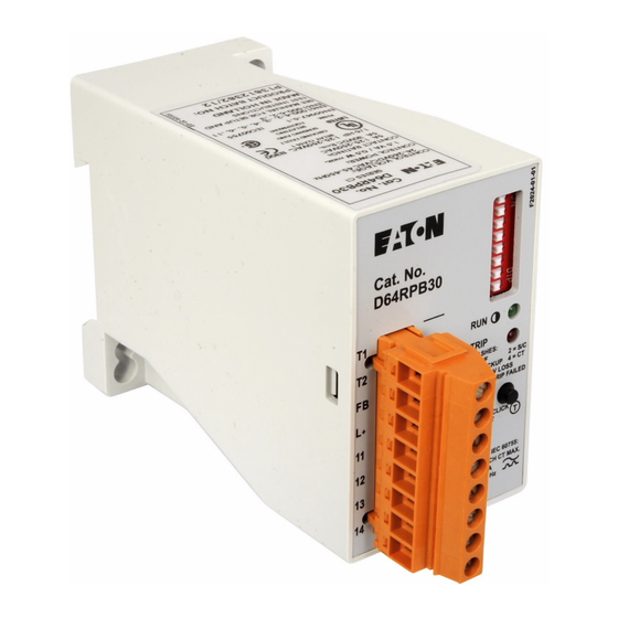
Figure 1. D64RPB30 Ground Fault Relay
1. FUNCTIONALITY
1.1 Ground fault current sensing and fault
reporting
The D64RPB30 is a microprocessor based
ground fault relay for use on solidly grounded or
resistance grounded systems.
The D64RPB30 employs an external 500:1
current transformer (CT) to measure ground
fault current flowing to ground in electrical power
distribution systems. The measured value is
compared against two setpoints. The lower one,
the Ground fault (G/F) setpoint, is settable from
30 mA to 9 A in 8 steps and has an associated
delay settable from 20 ms to 10 s in 6 steps. The
higher one, the Short Circuit (S/C) setpoint is
fixed at 125 A. When the current exceeds the
G/F setpoint for the set delay, but does not
reach the S/C level, a 'G/F' is diagnosed and the
unit trips by operating its internal relay. Should a
fault occur causing a ground fault current
exceeding the S/C setpoint, the D64RPB30
operates its relay without any delay diagnosing
an 'S/C'.
Effective 7/09
Cat. No.
D64RPB30
FLASHES:
1 = E/F
2 = S/C
2 = S/C
3 = BACKUP
4 = CT
4 = CT
5 = F/S CV LOSS
CONT' = TRIP FAILED
& OTHER
S1
DOUBLE CLICK
T
FOR TEST
RATINGS PER IEC 60755:
In
= SEE EACH CT MAX.
I n
= 0.03 - 9 A
= 45 - 450 Hz
F
Optionally, the user can select the operation of
the relay to be Type 2 Coordinated with an
upstream tripping device (fuse or breaker) to
protect any local contactor contacts in the case
of S/C faults. In this case the unit does not trip
initially when the measured current exceeds the
S/C setpoint, but waits for the upstream device
to take care of current interruption and then
trips. The latter trip flags the location of the fault
to the user and also allows him to instantly re-
close the upstream tripping device. Should the
upstream device fail to perform, then automatic
backup protection makes the D64RPB30 trip -as
a last resort- 20 ms or 300 ms, selected by
dipswitch, after the S/C occurred.
The relay contacts can be used in a trip or alarm
circuit. Form "Z", normally open and normally
closed contacts is provided.
The D64RPB30 is a Class A device as defined
in the IEC 60755 standard; therefore it is
designed for operation with sinusoidal AC and
pulsating DC currents.
1.2 External CT supervision
With any G/F protection scheme using an
external CT, there is an inherent risk that ground
faults will not be detected because of a bad or
deteriorated connection to the CT. Both open
circuits and shorts on the CT connection will
prevent detection. Therefore, the conventional
practice is to prove correct tripping regularly by
means of current injection. This is an annoying
procedure disrupting normal plant operation.
The D64RPB30 solves this problem by
constantly supervising the connection to the
external CT. Open circuits as well as shorts are
detected and will cause a trip.
Please note that the D64RPB30 does not
employ any DC injection to implement this
feature. Even small DC currents sent through
the secondary of a CT can bias its core enough
to shift the trip point outside specification on
sensitive settings.
IL04915001E
1
Advertisement
Table of Contents

Related Manuals for Eaton Cutler-Hammer D64RPB30 Series


Summary of Contents for Eaton Cutler-Hammer D64RPB30 Series
- Page 1 IL04915001E Instructions for D64RPB30 Series C1 Ground Fault Relay Optionally, the user can select the operation of the relay to be Type 2 Coordinated with an upstream tripping device (fuse or breaker) to protect any local contactor contacts in the case of S/C faults.
- Page 2 IL04915001E 1.4 Reset / Test pushbutton For the CT supervision feature to work a 500:1 ratio Series A2 C311CT must be installed, as The built-in momentary pushbutton is used to specified in section 5. verify the condition of the D64RPB30 if control voltage has been removed from the relay (see 1.3 LED indicators section 1.5) and to reset the internal relay and/or...
- Page 3 IL04915001E If the D64RPB30 is to be used for alarm only 1.6 Operating Modes purposes (rather than to interrupt ongoing processes), and the alarm has to have an auto- The D64RPB30 has four distinct Operating resetting operating mode, select one of the Modes.
-
Page 4: Dip Switch Settings
IL04915001E 2. DIPSWITCH SETTINGS Table 1. Dipswitch Settings In this table ‘R’ denotes right and ‘L’ denotes left. Parameter Set to Meaning Switch Refer to nos. section 1 2 3 Ground fault Trip Level L L L 30 mA L L R 100 mA L R L 500 mA... - Page 5 IL04915001E 2. Place the D64RPB30 in a clean dry 8. Integrate the relay contacts into the control enclosure. Locate the relay close to the circuit. Apply appropriate fusing to protect isolating device (circuit breaker or contactor) the contacts (13 A maximum). that is protecting the circuit being monitored.
- Page 6 IL04915001E 5. TECHNICAL SPECIFICATION Terminals Type Pull-apart UL/CSA rating 300 V AC, 10 A VDE rating 250 V AC, 12 A, pollution degree 3, over-voltage category III Insulation stripping length 7 mm (0.27 “) Torque 0.4 - 0.6 Nm (0.295 - 0.443 Ft. lb) Field wiring 0.5 - 2.5 mm (VDE), 20 - 14 AWG (UL/CSA), Cu, solid or...
- Page 7 Maximum fusing under EN 60947-5-1 13 A Future production of all Eaton C311CT Series 500:1 ratio CTs will be supplied with internal electronics to provide short circuit/open circuit detection by the D64RPB30 relay. These are designated Series A2, as shown above.
- Page 8 IL04915001E Environment Operating temperature -35 °C to +60 °C Storage temperature -40 °C to +80 °C Humidity 85% max (no condensation) Ingress protection IP20 Shock resistance (no malfunction) 10 G Vibration resistance (no malfunction) 10 G, 10 – 55 Hz at 1.5 mm double amplitude Mechanical Properties Width 45 mm...
-
Page 9: Power Source
IL04915001E POWER SOURCE GROUNDED SYSTEMS - 1 Phase 2 wire - 1 Phase 3 wire - 3 Phase 3 wire - 3 Phase 4 wire CURR ENT CARRYING NEUTRAL WHEN USED LOAD FIGURE 2 - D64RPB30 TYPICAL FIELD CONNECTION WITH EXTERNAL 500:1 CURRENT TRANSFORMER AND PULSED TRIP-AUTO RESET Effective 7/09... -
Page 10: Rear Panel Mounting
IL04915001E Dimensions 2.76 (70) 1.77 (45) 1.38 (35) Mounting hole Dia 0.22“ ( 5.5) 35 mm DIN RAIL DIN Rail Release REAR PANEL MOUNTING LEFT HAND SIDE VIEW D IN RAIL OR 2 SCREW Figure 3. Dimensions Drawing – Approximate Dimensions in Inches (mm) Table 2.
Need help?
Do you have a question about the Cutler-Hammer D64RPB30 Series and is the answer not in the manual?
Questions and answers