Table of Contents
Advertisement
Quick Links
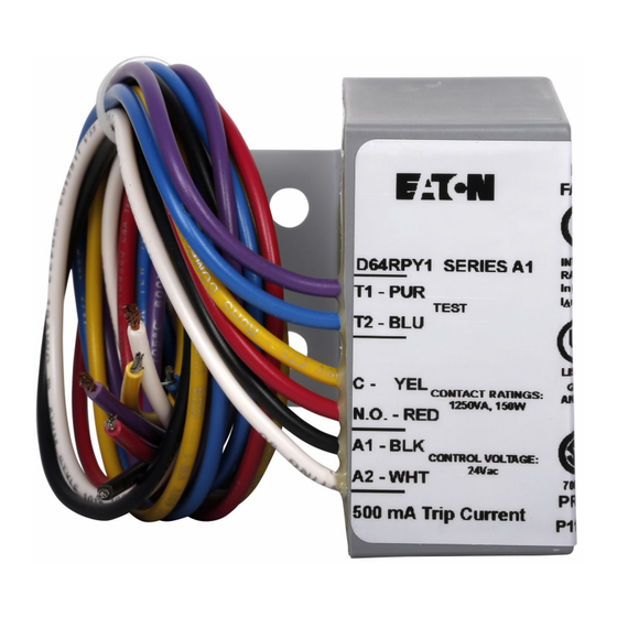
D64RPY2 SERIES A1 DIGITAL GROUND FAULT RELAY
N.O. TEST
PUSHBUTTON
N.C. CONTROL
CIRCUIT
N.O. CONTROL
CIRCUIT
24 VOLT AC
POWER SUPPLY
CANADA
Cutler-Hammer Canada
Eaton Yale Ltd.
3228 South Service Road
Burlington, Ontario,
L7R 3Y8
D64RPY2
Pub. No. IM-
Ser. A1, August, 2002
D64RPY2 INSTRUCTION MANUAL
PUBLICATION NO. IM-D64RPY2 SERIES A1
AUGUST, 2002
L
N
Page 1
INSTRUCTION
MANUAL
D64RPY2
U.S.A
Cutler-Hammer
4201 North 27th Street
Milwaukee, WI
53216
Advertisement
Table of Contents

Related Manuals for Eaton Cutler-Hammer D64RPY2 A1 Series


Summary of Contents for Eaton Cutler-Hammer D64RPY2 A1 Series
- Page 1 N.C. CONTROL CIRCUIT N.O. CONTROL CIRCUIT 24 VOLT AC POWER SUPPLY CANADA U.S.A Cutler-Hammer Canada Cutler-Hammer Eaton Yale Ltd. 4201 North 27th Street 3228 South Service Road Milwaukee, WI Burlington, Ontario, 53216 L7R 3Y8 Page 1 D64RPY2 Pub. No. IM-...
-
Page 2: Table Of Contents
INSTRUCTION MANUAL D64RPY2 D64RPY2 SERIES A1 DIGITAL GROUND FAULT RELAY TABLE OF CONTENTS PAGE TABLE OF CONTENTS ......................... LIST OF TABLES, FIGURES & FORMS ....................GENERAL DESCRIPTION ......................OPERATION ......................... GLOSSARY OF TERMS ....................RESET ......................... GROUND FAULT TEST ....................INSTALLATION INSTRUCTIONS .................... -
Page 3: General Description
INSTRUCTION MANUAL D64RPY2 D64RPY2 SERIES A1 DIGITAL GROUND FAULT RELAY GENERAL DESCRIPTION D64RPY2 is a microprocessor based ground fault relay for use on solidly grounded or resistance grounded systems. This innovative digital electronic relay measures ground fault current using a built-in 1.1” zero sequence current transformer (CT). -
Page 4: Reset
INSTRUCTION MANUAL D64RPY2 D64RPY2 SERIES A1 DIGITAL GROUND FAULT RELAY The Pulsed Trip Auto Reset mode is designed for applications where the output relay is operating a shunt trip device. The D64RPY2 resets automatically in approximately 20 milliseconds after the ground fault current is interrupted by the tripping action of the circuit breaker. -
Page 5: Connections
INSTRUCTION MANUAL D64RPY2 D64RPY2 SERIES A1 DIGITAL GROUND FAULT RELAY Refer to Figure 1. Pass the phase conductors through the CT window. If the neutral conductor is carrying single phase current, it is to be passed through the window. Do not pass ground conductors through the CT window. - Page 6 INSTRUCTION MANUAL D64RPY2 D64RPY2 SERIES A1 DIGITAL GROUND FAULT RELAY Output Relay: Contacts: Maximum UL rating: 8 A @ 250 V ac, general use 8 A @ 30 V dc, resistive TV-5 1/4 hp, 250 V ac (motor load) 600 W, 120 V ac (tungsten) 2 A, 530 VA, @ 265 V ac, pilot duty 43.2 VA, @ 30 V dc, pilot duty 22 LRA, 3.6 FLA, 30 V dc...
- Page 7 INSTRUCTION MANUAL D64RPY2 D64RPY2 SERIES A1 DIGITAL GROUND FAULT RELAY Mounting (refer to Figure 2): Two Screw ....................#8 x 1/2" (M4 x 12 mm) Weight: Open ....................... 0.82 lbs. (0.37 kg) Packaged ......................0.99 lbs. (0.45 kg) Applicable Standards: EN 50081-1 Electromagnetic compatibility (radiated emission), ‘household’...
-
Page 8: Output Relay Contact States
INSTRUCTION MANUAL D64RPY2 D64RPY2 SERIES A1 DIGITAL GROUND FAULT RELAY OPERATING PULSED AUTO RESET CONDITIONS 1.CONTROL POWER OFF CONTROL POWER ON 3.CONTROL POWER ON, FAULT CURRENT ABOVE TRIP + 3 Sec Pulse + 3 Sec Pulse SETTING & TRIP TIME 4.CONTROL NO RESET POWER ON,... -
Page 9: Typical Field Connection With Built-In Ct
INSTRUCTION MANUAL D64RPY2 D64RPY2 SERIES A1 DIGITAL GROUND FAULT RELAY POWER SOURCE GROUNDED SYSTEMS - 1 Phase 2 wire CURRENT CARRYING - 1 Phase 3 wire NEUTRAL, WHEN USED - 3 Phase 3 wire - 3 Phase 4 wire PUSH TO INVOKE TEST LOAD FIGURE 1 - TYPICAL FIELD CONNECTION USING BUILT IN CURRENT TRANSFORMER... -
Page 10: Dimensions And Weights D64Rpy2 Relay
INSTRUCTION MANUAL D64RPY2 D64RPY2 SERIES A1 DIGITAL GROUND FAULT RELAY 1.38 (35) PANEL BOTTOM .67 (17) 3.23 (82) LABEL FOLDS AROUND SIDE OF RELAY 1.26 (32) .35 (9) EN 50081-1 EN 50082-1 EN 61000-4-11 INTERNAL CT SENSOR RATINGS PER IEC 60755 In (A)= T1 - PUR 2.68... -
Page 11: Test Record
INSTRUCTION MANUAL D64RPY2 D64RPY2 SERIES A1 DIGITAL GROUND FAULT RELAY FORM 1 - TEST RECORD GROUND FAULT TEST – D64RPY2 The D64RPY2 has Blue and Purple wire leads for connection to a remote N.O. Test button. Pressing this button invokes a relay test. A simulated current of 600 milliamps (1.2 times the trip current) replaces the measured current.
Need help?
Do you have a question about the Cutler-Hammer D64RPY2 A1 Series and is the answer not in the manual?
Questions and answers