Table of Contents
Advertisement
CD H D Se r vo D r ive
Use r M a nua l
1 2 0 / 2 4 0 VAC a nd 4 0 0 / 4 8 0 VAC
Re vision : 8 .6
Fir m w a r e Ve rsion 1 .4 1 .x
Soft w a r e Ve r sion : 1 .4 1 .x .x
D OC- CD HD - UM - EN
I n t r oduct ion
Sa fe t y a n d
St a n da r ds
Spe cifica t ion s
W ir in g
D r ive Se tu p
Applica t ion Se t u p
M ot or Se t u p
Ope r a t ion
Tu n in g
D ia gn ost ics a n d
Tr ou ble shoot in g
Acce ssor ies
1
2
3
4
5
6
7
8
9
1 0
1 1
Advertisement
Table of Contents

Related Manuals for Servotronix CDHD Series


Summary of Contents for Servotronix CDHD Series
-
Page 1: Applica T Ion Se T U P
CD H D Se r vo D r ive Use r M a nua l 1 2 0 / 2 4 0 VAC a nd 4 0 0 / 4 8 0 VAC Re vision : 8 .6 Fir m w a r e Ve rsion 1 .4 1 .x Soft w a r e Ve r sion : 1 .4 1 .x .x D OC- CD HD - UM - EN I n t r oduct ion... - Page 3 CDHD Re vision H ist or y D ocu m e n t D a t e Re m a r k s Re vision Feb. 2017 Firm ware 1. 41.10. Min or cont ent updat e. Jan.2017 Firm ware 1. 41.10. Updat ed fault s/ warnings/ err ors. Updat ed m ult i- t urn encoder.
- Page 4 CDHD Con t a ct I n form at ion Servot ronix Mot ion Cont rol Lt d. 21C Yagia Kapayim St reet Pet ach Tikva 49130 I srael Tel: + 972 (3) 927 3800 Fax: + 972 ( 3) 922 8075 Websit e: www.servot ronix.com Te ch n ica l Su ppor t...
-
Page 5: Table Of Contents
CDHD Con t e n t s I n t r oduct ion _ _ _ _ _ _ _ _ _ _ _ _ _ _ _ _ _ _ _ _ _ _ _ _ _ _ _ _ _ _ _ _ _ _ _ _ _ _ _ _ _ _ _ _ _ _ _ _ 9 CDHD Product Overview ................ - Page 6 CDHD Cont rol Board Connect ions ................. 78 5.6.1 Cont roller I nt erface – C2 ..............78 5.6.2 Machine I nt erface – C3 ..............83 5.6.3 Mot or Feedback – C4..............85 5.6.4 Mot or Feedback Wiring Tables ............87 5.6.5 Mot or Brake on Power Block ............
- Page 7 CDHD 6.6.5 Sine Encoder and Resolver Diagnost ics ........... 146 Mot ion Unit s ................... 148 Current Foldback ..................149 Digit al I nput s ..................150 6.10 Digit al Out put s ..................150 6.11 Analog I nput s ..................151 6.11.1 Analog I nput 1 ................
- Page 8 CDHD Recording and Evaluat ing Perform ance ............206 9.6.1 Diagnost ics ................. 206 9.6.2 Recording Dat a in ServoSt udio ............207 9.6.3 Recording Dat a in Term inal ............209 9.6.4 Evaluat ing PTPVCMD ..............210 9.6.5 Evaluat ing I CMD and/ or PE Oscillat ions .......... 210 Low Pass Filt er on Current Com m and ............
-
Page 9: 1 I N T R Odu Ct Ion
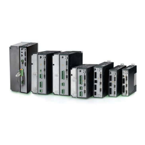
CDHD I nt roduct ion 1 I n t r odu ct ion 1 .1 CD H D Pr oduct Ove r vie w The CDHD is a full- feat ured, high- perform ance servo drive feat uring innovat ive t echnologies and indust ry-leading power densit y. -
Page 10: Cdhd Models
I nt roduct ion CDHD 1 .2 CD H D M ode ls The various m odels in t he CDHD servo drive series are different iat ed by m eans of t he com m unicat ion m et hods and prot ocols t hey use. The following t able present s t he different m odels and t heir dist inguishing charact erist ics. -
Page 11: Ordering I Nform At Ion
CDHD I nt roduct ion 1 .3 Or de r ing I nfor m a t ion The following diagram shows t he ordering opt ions t hat com prise t he various m odel num bers of t he drives in t he CDHD product line. These are t he current ly available ordering opt ions. -
Page 12: Docum Ent At Ion Set For Cdhd
I nt roduct ion CDHD 1 .4 D ocu m e n t a t ion Se t for CD H D The docum ent at ion set for t he CD HD servo drive consist s of t he following m anuals: ... -
Page 13: 2 Sa Fe T Y A Nd St A Nd A R Ds
CDHD Safet y and St andards 2 Sa fe t y a nd St a nd a r ds 2 .1 Sa fe t y Ove r vie w Only qualified persons m ay perform t he inst allat ion procedures. You do not need t o be an expert in m ot ion cont rol t o inst all and operat e t he drive syst em . - Page 14 Safet y and St andards CDHD All syst em com ponent s m ust be connect ed t o ground. Elect rical safet y is provided t hrough a low- resist ance eart h ground connect ion. ( Prot ect ive Class 1 according st andard EN/ I EC 618005- 1.) Mot or should be connect ed t o prot ect ive eart h by independent eart hing conduct or rat ed not less t han t he m ot or wire.
-
Page 15: St Andards Com Pliance
CDHD Safet y and St andards 2 .4 St a nda r ds Com plia nce The CDHD has been t est ed and according t o t he following st andards. Ta ble 2 - 1 . St a n da r ds Com plia nce St a n da r d D ir e ct ive/ D escr ipt ion Ce r t if. -
Page 16: Sto Cert Ificat Ion And Reliabilit Y Dat A
Safet y and St andards CDHD 2 .5 STO Ce r t ifica t ion a nd Re lia bilit y D a t a For com plet e det ails, refer t o CDHD Funct ional Safet y Reference Manual. 2 .6 M a t e r ia l Sa fe t y D a t a The CDHD is m arked is in accordance wit h SJ/ T 11364, which applies t o... -
Page 17: 3 Spe Cif Ica T Ion S
CDHD Specificat ions 3 Spe cif ica t ion s 3 .1 D im e n sion s A num ber of different fram es house t he various m odels of CDHD drives and power blocks. The ext erior dim ensions of t he fram es are shown in Figure 3- 1 t hrough Figure 3- 7. - Page 18 Specificat ions CDHD Figu r e 3 - 3 . CD H D - 0 0 8 / CD H D - 0 1 0 / CD H D - 0 1 3 ( 1 2 0 / 2 4 0 VAC) – D im e n sion s ( m m ) Figu r e 3 - 4 .
- Page 19 CDHD Specificat ions Figu r e 3 - 5 . CD H D - 0 0 3 / CD H D - 0 0 6 ( 4 0 0 / 4 8 0 VAC) – D im e n sions ( m m ) Figu r e 3 - 6 .
- Page 20 Specificat ions CDHD Figu r e 3 - 7 . CD H D - 0 2 4 / CD H D - 0 3 0 ( 4 0 0 / 4 8 0 VAC) – D im e n sions ( m m ) User Manual...
-
Page 21: Mechanical And Elect Rical Specificat Ions
CDHD Specificat ions 3 .2 M e cha nica l a nd Ele ct r ica l Spe cifica t ion s Ta ble 3 - 1 . M e ch a n ica l & Ele ct r ica l Spe cifica t ions – CD H D - 1 D 5 / CD H D - 0 0 3 ( 1 2 0 / 2 4 0 VAC) Sin g le Ph a se Spe cif ica t ion... - Page 22 Specificat ions CDHD Sin g le Ph a se Spe cif ica t ion CDH D- 1 D5 CDH D- 0 0 3 1 2 0 / 2 4 0 VAC Pow e r Te m p e ra t u re Norm ally operat es at quart er power;...
- Page 23 CDHD Specificat ions Sin g le a n d Th re e - Spe cif ica t ion CDH D- 4 D5 CDH D- 0 0 6 Ph a se 1 2 0 / 2 4 0 VAC Mot or Out put ( U, V, W) Cont inuou s Out put Current ( A rm s) Cont inuou s Out put Current ( A peak ) 6.63...
- Page 24 Specificat ions CDHD Ta ble 3 - 3 . M e ch a n ica l & Ele ct r ica l Spe cifica t ions – CD H D - 0 0 8 / CD HD - 0 1 0 / CD HD - 0 1 3 ( 1 2 0 / 2 4 0 VAC) Sin g le a n d Th re e Spe cif ica t ion CDH D- 0 0 8...
- Page 25 CDHD Specificat ions Sin g le a n d Th re e Spe cif ica t ion CDH D- 0 0 8 CDH D- 0 1 0 CDH D- Ph a se 1 2 0 / 2 4 0 VAC 0 1 3 * * Pow e r Te m p e ra t u re Norm ally operat es at quart er power;...
- Page 26 Specificat ions CDHD Th re e - Ph a se Spe cif ica t ion CDH D- 0 2 0 CDH D- 0 2 4 1 2 0 - 2 4 0 VAC Mot or Out put ( U, V, W) Cont inuou s Out put Current ( A rm s) Cont inuou s Out put Current ( A peak ) 28.28...
- Page 27 CDHD Specificat ions Ta ble 3 - 5 . M e ch a n ica l & Ele ct r ica l Spe cifica t ions – CD H D - 0 0 3 / CD H D - 0 0 6 / CD H D - 0 1 2 ( 4 0 0 / 4 8 0 VAC) Th re e Ph a se Spe cif ica t ion CDH D- 0 0 3 *...
- Page 28 Specificat ions CDHD Th re e Ph a se Spe cif ica t ion CDH D- 0 0 3 * CDH D- 0 0 6 * CDH D- 0 1 2 4 0 0 / 4 8 0 VAC Pow e r Te m p e ra t u re Norm ally operat es at quart er power;...
- Page 29 CDHD Specificat ions Ta ble 3 - 6 . M e ch a n ica l & Ele ct r ica l Spe cifica t ions – CD H D - 0 2 4 / CD H D - 0 3 0 ( 4 0 0 / 4 8 0 VAC) Th re e - Ph a se Spe cif ica t ion CDH D- 0 2 4...
-
Page 30: Cont Rol Specificat Ions
Specificat ions CDHD Th re e - Ph a se Spe cif ica t ion CDH D- 0 2 4 CDH D- 0 3 0 4 0 0 / 4 8 0 VAC Pow e r Te m p e ra t u re Fans Operat es at full power 80 ±... - Page 31 CDHD Specificat ions Fe a t u r e Spe cifica t ion Velocit y I nput / Out put Velocit y com m and / Current com m and Cont rol Update rate 125 μs (8 kHz) Perform ance Select able Velocit y Cont rol PI , PDFF, St andard pole placem ent , Adv ance pole placem ent , Loops...
-
Page 32: Prot Ect Ive Funct Ions And Environm Ent Al Specificat Ions
Specificat ions CDHD 3 .4 Pr ot e ct ive Fu nct ion s a nd Envir onm e nt a l Spe cifica t ion s Ta ble 3 - 8 . Pr ote ct ive Fu nct ions a n d En viron m en t a l Spe cs – All CD H D M ode ls Fe a t u r e Spe cifica t ion Prot ect iv e Funct ions... -
Page 33: I / O Specificat Ions
CDHD Specificat ions 3 .6 I / O Spe cifica t ions Ta ble 3 - 1 0 I / O Specifica t ion s Fe a t u r e Spe cifica t ion First Analog I nput Volt age Range Analog ±... - Page 34 Specificat ions CDHD Fe a t u r e Spe cifica t ion CDH D M o de l AP/ AF Quant it y Dig it a l Ou t pu t s Signal Configurable. Configurable. Configurable. Opt o- isolat ed. Opt o- isolat ed.
-
Page 35: Mot Or Feedback Specificat Ions
CDHD Specificat ions 3 .7 M ot or Fe e dba ck Spe cifica t ion s Ta ble 3 - 1 1 . M ot or Fe e dba ck Spe cifica t ions – All CD H D M ode ls Spe cifica t ion M ot or Fe e d ba ck... - Page 36 Specificat ions CDHD User Manual...
-
Page 37: 4 W Ir In G
CDHD Wiring 4 W ir in g 4 .1 CD H D - 1 D 5 / CD H D - 0 0 3 ( 1 2 0 / 2 4 0 V AC) W ir ing a nd Pin Assign m e n t s Daisy Chain Mains Single-Phase... - Page 38 PN 10126-3000PE (STX PN CONr00000026-31) or equiv. *** EC models only J-FAT-OT Key for spring 3M Solder Plug Junction Shell STX Servotronix connector PN 10326-52F0-008 (STX PN HODr00000026-00) or equiv. Mating Cable (STX PN CBL-MDRFL-26-0x, x=1|2|3 meter) 4/40 insert threads on C2, C3, C4 Highlighted PN Supplied with CDHD Figu r e 4 - 2 .
- Page 39 Crimping tool EJ-JFAJ3 (P2, P3) Extraction tool J-FAT-OT Key for spring STX Servotronix connector Highlighted PN Supplied with CDHD 4/40 insert threads on C2, C4 Figu r e 4 - 3 . Pin Assign m e n t s on CD H D - 1 D5 / CD HD - 0 0 3 –...
- Page 40 M4 ring or spade terminal or equivalent YRF-1070 (P2, P3, P4) Crimping tool EJ-JFAJ3 Extraction tool STX Servotronix J-FAT-OT Key for spring Highlighted PN Supplied with CDHD connector Figu r e 4 - 4 . Pin Assign m e n t s on CD H D - 1 D5 / CD HD - 0 0 3 –...
-
Page 41: Cdhd- 4D5/ Cdhd-006 ( 120/ 240 Vac) Wiring And Pin Assignm Ent S
CDHD Wiring 4 .2 CD H D - 4 D 5 / CD H D - 0 0 6 ( 1 2 0 / 2 4 0 V AC) W ir ing a nd Pin Assign m e n t s Daisy Chain Mains Single-Phase... - Page 42 PN 10126-3000PE (STX PN CONr00000026-31) or equiv. *** EC models only J-FAT-OT Key for spring 3M Solder Plug Junction Shell STX Servotronix connector PN 10326-52F0-008 (STX PN HODr00000026-00) or equiv. Highlighted PN Supplied with CDHD Mating Cable (STX PN CBL-MDRFL-26-0x, x=1|2|3 meter) 4/40 insert threads on C2, C3, C4 Figu r e 4 - 6 .
- Page 43 Crimping tool EJ-JFAJ3 Extraction tool J-FAT-OT Key for spring STX Servotronix connector 4/40 insert threads on C2, C4 Highlighted PN Supplied with CDHD Figu r e 4 - 7 . Pin Assign m e n t s on CD H D - 4 D5 / CD HD - 0 0 6 –...
- Page 44 PE: Terminal M4 YRF-1070 (P2, P3, P4) Crimping tool M4 ring or spade terminal EJ-JFAJ3 Extraction tool STX Servotronix J-FAT-OT Key for spring Highlighted PN Supplied with CDHD connector Figu r e 4 - 8 . Pin Assign m e n t s on CD H D - 4 D5 / CD HD - 0 0 6 –...
-
Page 45: Cdhd- 008/ Cdhd- 010/ Cdhd- 013 ( 120/ 240 Vac) Wiring And Pin Assignm Ent S
CDHD Wiring 4 .3 CD H D - 0 0 8 / CD H D - 0 1 0 / CD H D - 0 1 3 ( 1 2 0 / 2 4 0 VAC) W ir ing a nd Pin Assign m e n t s Daisy Chain Mains Three-Phase... - Page 46 PN 10126-3000PE (STX PN CONr00000026-31) or equiv. *** EC models only EJ-JFAJ4 (P2, P3, P4) Extraction tool 3M Solder Plug Junction Shell STX Servotronix EJ-JFAJ3 (P5) PN 10326-52F0-008 (STX PN HODr00000026-00) or equiv. Highlighted PN Supplied with CDHD Mating Cable (STX PN CBL-MDRFL-26-0x, x=1|2|3 meter) 4/40 insert threads on C2, C3, C4 Figu r e 4 - 1 0 .
- Page 47 Crimping tool YRF-1070 (P5) EJ-JFAJ4 (P2, P3, P4) Extraction tool STX Servotronix EJ-JFAJ3 (P5) Highlighted PN Supplied with CDHD 4/40 insert threads on C2, C4 Figu r e 4 - 1 1 . Pin Assign m e n t s on CD H D - 0 0 8 / CD HD - 0 1 0 / CD H D - 0 1 3 –...
- Page 48 Crimping tool or equivalent YRF-1130 (P2, P3, P4) Crimping tool YRF-1070 (P5) STX Servotronix EJ-JFAJ4 (P2, P3, P4) Extraction tool Highlighted PN Supplied with CDHD-PB EJ-JFAJ3 (P5) Figu r e 4 - 1 2 . Pin Assign m e n t s on CD H D - 0 0 8 / CD HD - 0 1 0 / CD H D - 0 1 3 –...
-
Page 49: Cdhd- 020/ Cdhd- 024 ( 120/ 240 Vac) Wiring And Pin Assignm Ent S
CDHD Wiring 4 .4 CD H D - 0 2 0 / CD H D - 0 2 4 ( 1 2 0 / 2 4 0 VAC) W ir ing a nd Pin Assign m e n t s Mains Three-Phase 120/240 VAC L-L... - Page 50 Molex 0638190000 (P1) Crimping tool 3M Solder Plug Junction Shell or equivalent STX Servotronix PN 10326-52F0-008 (STX PN HODr00000026-00) or equiv. Mating Cable (STX PN CBL-MDRFL-26-0x, x=1|2|3 meter) 4/40 insert threads on C2, C3, C4 Highlighted PN Supplied with CDHD Figu r e 4 - 1 4 .
- Page 51 PN 10326-52F0-008 (STX PN HODr00000026-00) or equiv. Mating Cable (STX PN CBL-MDRFL-26-0x, x=1|2|3 meter) Molex 0638190000 (P1) Crimping tool STX Servotronix or equivalent Highlighted PN Supplied with CDHD 4/40 insert threads on C2, C4 Figu r e 4 - 1 5 . Pin Assign m e n t s on CD H D - 0 2 0 / CD HD - 0 2 4 –...
- Page 52 Regen Bus - DC Bus + Mating Connector: PN SPC 5/2-STCL-7,62 (1718481) (STX PN CONr10000002-16) STX Servotronix Molex 0638190000 (P1, C3, C4) Crimping tool Highlighted PN Supplied with CDHD-PB or equivalent Figu r e 4 - 1 6 . Pin Assign m e n t s on CD H D - 0 2 0 / CD HD - 0 2 4 –...
-
Page 53: Cdhd- 003/ Cdhd- 006 ( 400/ 480 Vac) Wiring And Pin Assignm Ent S
CDHD Wiring 4 .5 CD H D - 0 0 3 / CD H D - 0 0 6 ( 4 0 0 / 4 8 0 VAC) W ir ing a nd Pin Assign m e n t s Mains Three-Phase Max. - Page 54 Molex 0638190000 (P1, P2) 3M Solder Plug Junction Shell Crimping tool or equivalent STX Servotronix PN 10326-52F0-008 (STX PN HODr00000026-00) or equiv. Mating Cable (STX PN CBL-MDRFL-26-0x, x=1|2|3 meter) 4/40 insert threads on C2, C3, C4 Highlighted PN Supplied with CDHD Figu r e 4 - 1 8 .
- Page 55 PN SPC 5/3-STCL-7,62 (1718494) (STX PN CONr10000003-21) Molex 0638190000 (P1, P2) Crimping tool STX Servotronix or equivalent Highlighted PN Supplied with CDHD 4/40 insert threads on C2, C4 Figu r e 4 - 1 9 . Pin Assign m e n t s on CD H D - 0 0 3 / CD HD - 0 0 6 –...
- Page 56 Contacts – PN 0430300001 or equivalent (STX PN PINr43030000-00) Functional Ground PE: Terminal M4 M4 ring or spade terminal STX Servotronix Molex 0638190000 (P1, P2, C3, Crimping tool Highlighted PN Supplied with CDHD-PB C4) or equivalent Figu r e 4 - 2 0 . Pin Assign m e n t s on CD H D - 0 0 3 / CD HD - 0 0 6 –...
-
Page 57: Cdhd- 012 (400/ 480 Vac) Wiring And Pin Assignm Ent S
CDHD Wiring 4 .6 CD H D - 0 1 2 ( 4 0 0 / 4 8 0 V AC) W ir ing a nd Pin Assign m e n t s Mains Three-Phase Daisy Chain Max. 528 VAC L-L RS232 EtherCAT Rotary Switches... - Page 58 3M Solder Plug Junction Shell Molex 0638190000 (P1, P2) Crimping tool PN 10326-52F0-008 (STX PN HODr00000026-00) or equiv. STX Servotronix or equivalent Mating Cable (STX PN CBL-MDRFL-26-0x, x=1|2|3 meter) Highlighted PN Supplied with CDHD 4/40 insert threads on C2, C3, C4 Figu r e 4 - 2 2 .
- Page 59 PN SPC 5/3-STCL-7,62 (1718494) (STX PN CONr10000003-21) Molex 0638190000 (P1, P2) Crimping tool STX Servotronix or equivalent Highlighted PN Supplied with CDHD 4/40 insert threads on C2, C4 Figu r e 4 - 2 3 . Pin Assign m e n t s on CD H D - 0 1 2 –...
- Page 60 Motor Phase V Motor Phase W Mating Connector PN SPC 5/3-STCL-7,62 (1718494) (STX PN CONr10000003-21) STX Servotronix Molex 0638190000 (P1, P2, C3, Crimping tool C4) or equivalent Highlighted PN Supplied with CDHD Figu r e 4 - 2 4 . Pin Assign m e n t s on CD H D - 0 1 2 –...
-
Page 61: Cdhd- 024/ Cdhd- 030 ( 400/ 480 Vac) Wiring And Pin Assignm Ent S
CDHD Wiring 4 .7 CD H D - 0 2 4 / CD H D - 0 3 0 ( 4 0 0 / 4 8 0 VAC) W ir ing a nd Pin Assign m e n t s Daisy Chain RS232 Rotary Switches... - Page 62 PN SPC 5/3-STCL-7,62 (1718494) (STX PN CONr10000003-21) Molex 0638190000 (P1, P2, P3) Crimping tool STX Servotronix or equivalent Highlighted PN Supplied with CDHD 4/40 insert threads on C2, C4 Figu r e 4 - 2 6 . Pin Assign m e n t s on CD H D - 0 2 4 / CD HD - 0 3 0 –...
- Page 63 PN SPC 5/3-STCL-7,62 (1718494) (STX PN CONr10000003-21) Molex 0638190000 (P1, P2, P3) Crimping tool STX Servotronix or equivalent Highlighted PN Supplied with CDHD 4/40 insert threads on C2, C4 Figu r e 4 - 2 7 . Pin Assign m e n t s on CD H D - 0 2 4 / CD HD - 0 3 0 –...
-
Page 64: Cont Roller I Nt Erface Wiring
Wiring CDHD 4 .8 Cont r olle r I n t e r fa ce W ir ing Figu r e 4 - 2 8 . Con t r olle r I n t e rfa ce W ir in g – AP/ AF M ode ls User Manual... - Page 65 CDHD Wiring Figu r e 4 - 2 9 . Con t r olle r I n t e rfa ce W ir in g – EC Mode ls Figu r e 4 - 3 0 . Con t r olle r I n t e rfa ce W ir in g – EB M ode ls User Manual...
-
Page 66: Machine I Nt Erface Wiring
Wiring CDHD 4 .9 M a chine I nt e r fa ce W ir ing Figu r e 4 - 3 1 . M a ch in e I n te r face W ir in g D ia gra m – AP/ AF M ode ls User Manual... - Page 67 CDHD Wiring Figu r e 4 - 3 2 . M a ch in e I n te r face W ir in g D ia gra m – EC M ode ls User Manual...
- Page 68 Wiring CDHD User Manual...
-
Page 69: 5 D R Iv E Se T U P
CDHD Drive Setup 5 D r iv e Se t u p 5 .1 Se t up Ove r vie w Perform t he following st eps t o inst all and set up a CDHD syst em . Mount t he CDHD. Make all elect rical connect ions: Cont roller I / Os and/ or Machine I / Os ... - Page 70 Drive Setup CDHD CD H D - 4 D 5 I t e m CD H D - 0 0 6 Crim ping t ool Molex 0638190000 ( P1) Crim ping t ool YRF- 1070 ( P2, P3, P4) Ext ract ion t ool EJ- JFAJ3 Key for spring connect or J- FAT- OT (supplied)
-
Page 71: Host Com Put Er Syst Em
CDHD Drive Setup To connect t he CDHD t o t he host com put er via serial com m unicat ion, you will need one of t he following: USB 2.0 A t o Mini-B cable ( USB int erface) ... -
Page 72: Emi Suppression
Drive Setup CDHD 5 .3 EM I Suppr e ssion 5 .3 .1 CE Filt e r in g Te ch n iqu e s The CDHD drive com plies wit h t he CE st andards specified in t he sect ion St andards Com pliance. -
Page 73: Shielding And Bonding
CDHD Drive Setup ground. Provide an elect rical connect ion across t he ent ire back surface of t he drive panel. Elect rically-conduct ive panels such as alum inum or galvanized st eel are recom m ended. For paint ed and ot her coat ed m et al panels, rem ove all coat ing behind t he drive. -
Page 74: I Nput Power Filt Ering
Drive Setup CDHD Mot or and feedback cables m ust be shielded in order t o m inim ize noise em issions and increase t he im m unit y levels of t he drive syst em . The shield should be connect ed t o ground at bot h ends. -
Page 75: I / O Signal Filt Ering
CDHD Drive Setup ( line-t o- line) . Filt ering t he lines feeding t he m ot or provides addit ional reduct ion of noise current s t hat ent er surrounding cables and equipm ent I / O port s in close proxim it y. -
Page 76: Leakage Current Considerat Ions
Drive Setup CDHD Fu se h older s: St andard fuse blocks, or finger-safe fuse holders according t o I EC 60529. For exam ple: Bussm ann: CH Series m odular fuse holders, fuse size 0 t o 30A, class J, ... -
Page 77: Mechanical I Nst Allat Ion
CDHD Drive Setup 5 .5 M e cha nica l I nst a lla t ion 5 .5 .1 M ou n t in g t h e CD HD Using t he bracket on t he back of t he CDHD, m ount t he CDHD on a grounded conduct ive m et al panel. -
Page 78: Cont Rol Board Connect Ions
Drive Setup CDHD 5 .6 Cont r ol Boa r d Con ne ct ions The cont rol board int erfaces vary depending on t he specific CDHD m odel, as det ailed in t he following t able. The connect ors for int erfaces C2, C3 and C4 can be fast ened by eit her lat ch or screw. - Page 79 CDHD Drive Setup AP/ AF M ode ls – Con t rolle r To preserve isolat ion of t he digit al I / Os, connect a 24 VDC source t o pin 19. Connect t he ret urn of t he 24 VDC supply t o pin 1, which funct ions as t he ground pat h for t he out put s.
- Page 80 Drive Setup CDHD Ta ble 5 - 3 . Con t r olle r I n t e rfa ce – AP/ AF M ode ls Pin Fu n ct ion De scrip t ion Fu n ct ion De scrip t ion 24 VDC ret urn 24 VDC Ret urn of t he user- supplied...
- Page 81 CDHD Drive Setup Pin Fu n ct ion De scrip t ion Fu n ct ion De scrip t ion Analog input 2- Low side of t he second different ial analog input ( ± 10 VDC) 18* Analog input 2+ High side of t he second Analog out put Analog out put , referenced t o different ial analog input...
- Page 82 Drive Setup CDHD Pin Fu n ct ion De scrip t ion Pin Fu n ct ion De scrip t ion Digit al input 6 Digit al out put 2 Fast opt o- isolat ed Opt o- isolat ed program m able program m able digit al input .
-
Page 83: Machine I Nt Erface - C3
CDHD Drive Setup 5 .6 .2 M a ch in e I n t e r fa ce – C3 M a ch in e I / Os are connect ed t hrough int erface C3 . Wire t he m achine input s and out put s according t o t he requirem ent s of your applicat ion. - Page 84 Drive Setup CDHD M a chine I / Os – I n t er fa ce a n d Pin Assign m en t s Ta ble 5 - 6 . M a ch in e I / O I n t er face Fu n ct ion De scrip t ion Fu n ct ion...
-
Page 85: Mot Or Feedback - C4
CDHD Drive Setup 5 .6 .3 M ot or Fe e dba ck – C4 M ot or Fe e dba ck uses int erface C4 . Wire t he m ot or feedback int erface according t o t he t ype of feedback device t o be used in your applicat ion. - Page 86 Drive Setup CDHD AP M ode ls – M ot or Fee dba ck Ta ble 5 - 7 . M ot or Fe e dba ck I n t e rfa ce – AP Mode ls Fu n ct ion Fu n ct ion I ncrem ent al encoder A + I ncrem ent al encoder A -...
-
Page 87: Mot Or Feedback Wiring Tables
CDHD Drive Setup EB M ode ls – M ot or Fee dba ck Ta ble 5 - 9 . M ot or Fe e dba ck I n t e rfa ce – EB M ode ls Fu n ct ion Fu n ct ion I ncrem ent al encoder A + I ncrem ent al encoder A -... - Page 88 Drive Setup CDHD W ir in g – BiSS- C En code r Ta ble 5 - 1 1 . BiSS- C Encoder Pin # Tw ist e d Pa ir Use r Mot or Pin # Sign a l D e scr ipt ion Serial Dat a + ( SLO+ ) Twist ed Pair Serial Dat a - (SLO- )
- Page 89 CDHD Drive Setup W ir in g – Sin gle - En de d H alls Ta ble 5 - 1 3 . Fe e dba ck W ir in g – Sin gle - En de d H a lls Pin # Tw ist e d Pa ir Use r Mot or Pin # Sign a l D e scr ipt ion...
- Page 90 Drive Setup CDHD To use different ial Halls wit h A quad B and index, connect t he Halls t o t he Machine int erface as follows: Hall U+ t o Machine I / F pin 1, Hall U- t o Machine I / F pin 11. Hall V+ t o Machine I / F pin 2, Hall V- t o Machine I / F pin 12.
- Page 91 CDHD Drive Setup W ir in g – Ta m a ga w a I n crem e nt a l Ta ble 5 - 1 6 . Fe e dba ck W ir in g – Ta m a ga w a I ncr e m e n t a l Pin # Tw ist e d Pa ir Use r Mot or Pin # Sign a l D e scr ipt ion...
- Page 92 Drive Setup CDHD W ir in g – Sin e En code r Ta ble 5 - 1 7 . Fe e dba ck W ir in g – Sine Encoder Pin # Tw ist e d Pa ir Use r Mot or Pin # Sign a l D e scr ipt ion Sine Encoder Sine+ Twist ed Pair...
- Page 93 CDHD Drive Setup W ir in g – Sin e En code r w it h I n dex Ta ble 5 - 1 9 . Fe e dba ck W ir in g – Sine Encoder w it h I n de x Pin # Tw ist e d Pa ir Use r Mot or Pin # Sign a l D e scr ipt ion...
- Page 94 Drive Setup CDHD W ir in g – Sick 5 V ( H I PERFACE Pr ot ocol a n d Sine Signa l) Ta ble 5 - 2 1 . Fe e dba ck W ir in g – Sick 5 V ( H I PERFACE Prot ocol a n d Sine Sign a l) Pin # Tw ist e d Pa ir Use r Mot or Pin #...
- Page 95 CDHD Drive Setup W ir in g – H EI D EN H AI N ( En Da t 2 .x Com m u nica t ion On ly) Ta ble 5 - 2 3 . Fe e dba ck W ir in g – H EI DEN HAI N ( En Da t 2 .x Com m u n ica t ion On ly) Pin # Tw ist e d Pa ir Use r Mot or Pin #...
- Page 96 Drive Setup CDHD W ir in g – N ikon / Ta m a ga w a | I n cr em en t a l 1 7 - bit | Sin gle Tu rn Ta ble 5 - 2 5 . Fe e dba ck W ir in g –...
-
Page 97: Mot Or Brake On Power Block
CDHD Drive Setup W ir in g – Re solve r Ta ble 5 - 2 7 . Fe e dba ck W ir in g – Resolve r Pin # Tw ist e d Pa ir Use r Mot or Pin # Sign a l D e scr ipt ion Resolver Sine + Twist ed Pair... -
Page 98: Fieldbus Devices - C5 And C6
Drive Setup CDHD Ta ble 5 - 2 9 . M ot or Br a ke Con t rol M a t in g Con ne ctor I t e m All M ode ls Manufact urer Molex* Housing and 436450300* and 4- pin crim p 0430300001*... -
Page 99: Host Com Put Er - C1 And/ Or C7
CDHD Drive Setup 5 .6 .7 H ost Com pu t e r – C1 a n d/ or C7 The drive can be connect ed t o t he host com put er t hrough eit her one of t he following int erfaces: USB por t . -
Page 100: Daisy Chain - C8
Drive Setup CDHD 5 .6 .8 D a isy Ch a in – C8 N ot e: EB m odels do not have Daisy Chain port . The CDHD can be addressed and cont rolled on a daisy- chained RS232 line. I n a daisy- chain RS232 configurat ion, all drives m ust be daisy-chained t hrough t he C8 connect or. -
Page 101: Power Board Connect Ions - 120/ 240 Vac
CDHD Drive Setup Figu r e 5 - 1 4 . D r ive Addre ss Rot a r y Sw itch es 5 .7 Pow e r Boa r d Conne ct ion s – 1 2 0 / 2 4 0 VAC On m ost CDHD 120/ 240 VAC m odels, t he power board has t he following int erfaces: ... -
Page 102: Mot Or
Drive Setup CDHD Ta ble 5 - 3 4 . STO I n t er face Pin La be l Fu n ct ion STO Enable 2 4 V STO Ret urn GN D 24V Ret urn, provided by t he drive for use wit h em ergency st op circuit 24V Supply, provided by t he drive for use wit h em ergency st op circuit... -
Page 103: Regenerat Ion Resist Or
CDHD Drive Setup Ta ble 5 - 3 7 . M ot or I n t er face M a t in g Con n ect or s I t e m CD H D - 1 D 5 , CD HD - 0 0 3 Manufact urer JST J300 Housing and... - Page 104 Drive Setup CDHD Figu r e 5 - 1 7 . Re ge n I n t e rfa ce ( show n he r e: CD H D - 0 0 6 ) Ta ble 5 - 3 8 . Re ge n I n t e rfa ce CD H D - 1 D 5 , CD HD - 0 0 3 CD H D - 4 D 5 , CD HD - 0 0 6...
-
Page 105: Ac I Nput Volt Age
CDHD Drive Setup Ta ble 5 - 4 0 . AC I n pu t Volt a ge / Re ge n I n te rfa ce M a t in g Con n ect or I t e m CD H D - 1 D 5 , CD HD - 0 0 3 Manufact urer JST J300... - Page 106 Drive Setup CDHD Connect L1, L2 and L3 (for bus power) . I f t he m ain volt age is from a single- phase source, connect line and neut ral t o L1 and L2. I f t he m ain volt age is from a t hree- phase source, connect t he phases t o ...
- Page 107 CDHD Drive Setup CD H D - 0 0 8 CD H D - 0 1 0 CD H D - 0 1 3 Pin La be l Fu n ct ion AC Phase 1 AC Phase 2 AC Phase 3 Logic AC Phase 1 L1 C Logic AC Neut ral...
-
Page 108: Mot Or Brake ( Opt Ional)
Drive Setup CDHD 5 .7 .5 M ot or Br a k e ( Opt ion a l) The CDHD 120/ 240 VAC m odels do not have sufficient am perage t o act ivat e a m ot or brake. The CDHD can be connect ed t o a m ot or brake via a relay, as shown in t he exam ple below. -
Page 109: Power Board Connect Ions - 400/ 480 Vac
CDHD Drive Setup 5 .8 Pow e r Boa r d Conne ct ion s – 4 0 0 / 4 8 0 VAC On all CDHD 400/ 480 VAC m odels, t he power board has t he following int erfaces: STO –... -
Page 110: Logic Power 24V I Nput
Drive Setup CDHD Ta ble 5 - 4 3 . STO I n t er face Pin La be l Fu n ct ion STO Enable 24 VDC Ret urn Ta ble 5 - 4 4 . STO I n t er face M a t in g Con n ect or I t e m All M ode ls Manufact urer... -
Page 111: Ac I Nput And Regenerat Ion Resist Or
CDHD Drive Setup Ta ble 5 - 4 6 . Logic Pow e r 2 4 V I n pu t I n t er face Ma t in g Con n e ctor I t e m All M ode ls Manufact urer Molex Housing and... -
Page 112: Mot Or Brake
Drive Setup CDHD Ta ble 5 - 4 7 . AC I n pu t a n d Re ge ne r a t ion Re sistor I n te r face Pin La be l Fu n ct ion AC Phase 1 AC Phase 2 AC Phase 3... - Page 113 CDHD Drive Setup Ta ble 5 - 4 9 . Br a k e I n te rfa ce Pin La be l Fu n ct ion Mot or Brake + Mot or Brake - Ta ble 5 - 5 0 . Br a k e I n te rfa ce M a t in g Conn e ctor I t e m All M ode ls...
- Page 114 Drive Setup CDHD The following t able and diagram show t he condit ions which m ay result in t he det ect ion and declarat ion of a fault . Ta ble 5 - 5 1 . Br a k e Fa u lt Con dit ion s M ode l CD H D - 0 0 3 CD H D - 0 1 2...
-
Page 115: Mot Or
CDHD Drive Setup 5 .8 .5 M ot or M ot or uses int erface P5 on all 400/ 480 VAC m odels: Figu r e 5 - 2 8 . M ot or I n t er face Ta ble 5 - 5 2 . M ot or I n t er face Pin La be l Fu n ct ion... -
Page 116: Regenerat Ion Resist Ence Calculat Ions
Drive Setup CDHD To det erm ine whet her a syst em requires a regenerat ion resist or, and if so, t he level of capacit y, refer t o t he sect ion Regenerat ion Resist ance Calcuat ions t o calculat e syst em propert ies. - Page 117 CDHD Drive Setup Ta ble 5 - 5 6 . Bu s Specifica t ion s - Th r ee Ph ase 4 0 0 / 4 8 0 L- L VAC D r ive Ca pa cit a n ce I n t e rn a l r e ge n N OM H igh...
- Page 118 Drive Setup CDHD Energy dissipat ed by frict ion ( J or ft ·lb) frict ion Frict ion t orque ( N·m or lb·ft ) ω Speed at t he st art of decelerat ion ( rad/ s) ω Speed at t he end of decelerat ion ( rad/ s) Tim e of decelerat ion ( s) D e t e r m in in g t he Ene r gy t o be D issipa te d by t h e Am plifie r m ot or...
- Page 119 CDHD Drive Setup Current during decelerat ion ( ARMS/ phase) Motor resistance (Ω L- L) D e t e r m in in g t he Aver a ge D issipa t e d Pow e r C( V High cycle Where: Tot al energy needs t o be dissipat ed by t he am plifier ( J)
- Page 120 Drive Setup CDHD Tim e of De ce le r a t ion Ca lcu la t ion �J �∙ ( ω = (0.000484+0.001)∙(261)/(19.8+1.5) = 0.0181 s Mot or Load Cu r r e n t D u r in g De ce le r a t ion Ca lcu la t ion �J �...
-
Page 121: Regenerat Ion Resist Or Prot Ect Ion
CDHD Drive Setup = 220 Vrm s = 340 VDC Tim e bet ween decelerat ion = 5 s Tim e of De ce le r a t ion Ca lcu la t ion �J �∙ ( ω (0. 0006562+ 0. 0015) ( 261) Mot or Load = 0.03 s... - Page 122 Drive Setup CDHD Re gen e ra t ion Re sist or Pa ra m e t e r s The regenerat ion resist or capacit y is defined by t hree param et ers. To act ivat e t he regenerat ion resist or prot ect ion funct ion in t he CDHD, param et er REGENRES and/ or param et er REGENPOW m ust be set t o a value ot her t han - 1 , which is t he default value.
-
Page 123: 5 .1 0 Fir M W A R E Upda T E
CDHD Drive Setup Ex a m ple : D e t e rm inin g t h e M a x im um On Tim e The regenerat ion resist or has t he following propert ies: REGENRES = 100 [Ω] REGENPOW = 60 [ W] CDHD V = 400 [ V]... - Page 124 Drive Setup CDHD The pat h and nam e of t he file cont aining t he firm ware Fir m w a r e Pa th updat e. The file nam e indicat es t he firm ware version; for exam ple: 1_41_4* .sfw represent s firm ware version 1.41.4.
-
Page 125: Firm Ware Updat E Over Serial Connect Ion
CDHD Drive Setup 5 .1 0 .3 Fir m w a r e Upda t e ov e r Se r ia l Con n e ct ion Pr oce du re – Upda t in g D r ive Fir m w ar e ove r Se r ia l Con n ect ion Download t he drive’s firm ware file ( * .sfw) from t he product web page t o a host com put er. - Page 126 Drive Setup CDHD Figu r e 5 - 3 1 . I n TwinCAT connect t o CDHD drive. For inst ruct ions, refer t o t he Et herCAT and CANopen Reference Manual for CDHD Servo Drive ( CDHD_Et herCAT_CANopen_fw1.41.2_Rev.6.3.pdf) I n t he TwinCAT navigat ion m enu, select I / O >...
- Page 127 CDHD Drive Setup Go t o t he On lin e t ab. Click Boot str a p. Wait unt il Current St at es becom es BOOT. Figu r e 5 - 3 3 . Click Dow n loa d. The File Manager dialog box opens.
- Page 128 Drive Setup CDHD The Edit FoE Nam e dialog box opens. Do not change anyt hing in t his dialog box. Sim ply click OK. Figu r e 5 - 3 5 . The firm ware updat e process begins. E is displayed on t he CDHD 7-segm ent display panel.
-
Page 129: Resum Ing Operat Ion Aft Er Firm Ware Updat E
CDHD Drive Setup When t he firm ware updat ed is com plet ed, t he Current St at e swit ches from BOOT t o PREOP. Figu r e 5 - 3 7 . 5 .1 0 .5 Re su m in g Ope r a t ion Aft e r Fir m w a r e Upda t e Pr oce du re –... -
Page 130: 5 .1 1 Pow E R Up
Drive Setup CDHD To act ivat e t he Hardware Em ber m ode, use a sm all screwdriver or sim ilar t ool t o press t he Hardware Em ber swit ch. This swit ch is locat ed on t he t op of t he drive next t o t he daisy chain connect or ( C8) . -
Page 131: Param Et Ers
CDHD Applicat ion Set up 6 App lica t ion Se t u p 6 .1 Pa r a m e t e r s 6 .1 .1 Con figu r a t ion Pa r a m e t e r s Va r Com is a propriet ary set of com m ands and variables, or param et ers, used t o configure drive funct ionalit y when t he host and drive are com m unicat ing over a serial connect ion. -
Page 132: Configurat Ion Sequence
Applicat ion Set up CDHD Figu r e 6 - 1 . M e m or y an d Com m a n ds for M an a gin g Pa r am e t e r s I n ServoSt udio, drive param et ers can be saved t o non- volat ile m em ory at any t im e by clicking t he Sa ve but t on on t he t oolbar. - Page 133 CDHD Applicat ion Set up Optional: Power Rating Application Setup (in any order) Motor Feedback Motion Units Current Foldback Digital I nputs/ Outputs Analog I nputs/ Outputs Homing Disable Mode Motor Setup Communication (using Wizard) Drive I D Motor I D Motor Phasing Current Limits Velocity Limits...
-
Page 134: Com M Unicat Ion
Applicat ion Set up CDHD 6 .3 Com m u nica t ion Com m issioning t he drive t hrough ServoSt udio requires a serial RS232 or USB connect ion. Once t he drive is configured, you can t hen connect it t o a PLC or cont roller over an Et herCAT, CANopen or ot her fieldbus net work. -
Page 135: Canopen Bit Rat E
CDHD Applicat ion Set up Type a com m and t o change t he baud rat e; for exam ple: BAUD RATE 1 9 2 0 0 Press En t er . Com m unicat ion is lost as soon as En t er is pressed, and ServoSt udio goes offline. -
Page 136: Feedback
Applicat ion Set up CDHD Va r Com D e scr ipt ion DI CONT Drive cont inuous current . Defined in hardware. Read only. DI PEAK Drive peak current . Defined in hardware. Read only. OVTHRESH The level for det ect ion of bus over- volt age. Defined in hardware. - Page 137 CDHD Applicat ion Set up Va r Com D e scr ipt ion MENCTYPE The t ype of encoder being used on t he m ot or. MENCRES The resolut ion of t he encoder, in num ber of lines per revolut ion of t he m ot or.
-
Page 138: Sine Encoder
Applicat ion Set up CDHD Ph a se Fin din g The Phase Finding procedure is used t o init ialize com m ut at ion for increm ent al encoder syst em s. You can also use t he com m and Fin d Ph a se in t he ServoSt udio M ot or Fe e dba ck screen t o det erm ine t he correct com m ut at ion. -
Page 139: Biss- C I Nt Erface
CDHD Applicat ion Set up Va r Com D e scr ipt ion MTTURNRESET Reset s t he posit ion count er of an absolut e m ult i- t urn encoder, and clears bat t ery no volt age fault . I GNOREBATTFLT Prevent s a m ult i-t urn absolut e encoder from issuing a fault due t o a dead, disconnect ed or m issing backup bat t ery,... -
Page 140: Encoder Sim Ulat Ion Out Put
Applicat ion Set up CDHD CDHD support s t he EnDat 2.1 com m unicat ion prot ocol, which is a subset of t he EnDat 2.2 prot ocol. All EnDat 2.2 capable devices support t he 2.1 prot ocol, including t he com m ands and queries t hat are relevant t o CDHD;... -
Page 141: Resolver
CDHD Applicat ion Set up These parameters are defined by user ENCOUTMODE 0 – OFF 1 – ON 2 – ON, Index pulse goes directly from motor via FPGA to C2 ENCOUTRES ±10,000,000 (no 0) ENCOUTZPOS 0 to 40000000 Notes and Limitations: Index location is relative to the real index MENCTYPE 0,1, 2 or at zero electrical degree MENCTYPE 3, 4, 6 ENCOUTZPOS is not applicable in ENCOUTMODE 0 and 2... -
Page 142: Resolver And Sine Encoder Calibrat Ion
Applicat ion Set up CDHD Va r Com D e scr ipt ion RESBW The resolver conversion bandwidt h. High bandwidt h produces bet t er dynam ic t racking and less phase lag in high frequencies. Lower bandwidt h result s in bet t er noise reduct ion. -
Page 143: Mot Or Speed Lim It At Ions During Calibrat Ion
CDHD Applicat ion Set up cycles. I f running t he m ot or in one direct ion, t he num ber of revolut ions required for t he calibrat ion is calculat ed as follows: MRESPOLES Re solver : 128 ÷ Where MENRESPOLES is t he num ber of individual poles in t he resolver feedback device. - Page 144 Applicat ion Set up CDHD Pr oce du re - Re solve r Ca libr a t ion Usin g Se rvoSt u dio I n t he Fee dba ck screen, select Feedback > Resolve r . Figu r e 6 - 6 . I n t he M ot ion screen, set t he param et ers, for exam ple: Select Operat ion Mode>...
- Page 145 CDHD Applicat ion Set up I n t he Fee dba ck screen, set t he following: Figu r e 6 - 8 . Not e t hat Sine/ Cosine Calibrat ion St at us is 0 . Figu r e 6 - 9 . Press t he Sta r t but t on t o begin t he calibrat ion procedure.
-
Page 146: Sine Encoder And Resolver Diagnost Ics
Applicat ion Set up CDHD Ex a m ple : The m ot or runs in a velocit y cont rol loop at 6 rpm , and t he calibrat ion procedure is execut ed. Figu r e 6 - 1 1 . Pr oce du re - Sin e En code r Ca libr a t ion Usin g Se r voSt u dio ServoSt udio does not current ly support sine encoder calibrat ion. - Page 147 CDHD Applicat ion Set up Figu r e 6 - 1 2 . Ex a m ple of Sin e Encode r Recor din g A t ypical recording of resolver m ight look as shown in Figure 6- 13: Figu r e 6 - 1 3 .
-
Page 148: Mot Ion Unit S
Applicat ion Set up CDHD The result ing plot in t he Scope screen will look sim ilar t o one shown in Figure 6- 14. This plot shows t he signal levels of t he act ual input signal ( in volt s) . As expect ed, t he sine encoder signals are close t o 1V peak -t o- peak. -
Page 149: Current Foldback
CDHD Applicat ion Set up Va r Com D e scr ipt ion UNI TSROTVEL The unit s of velocit y variables in a rot ary syst em . UNI TSROTACC The unit s of accelerat ion and decelerat ion variables in a rot ary syst em . -
Page 150: Digit Al I Nput S
Applicat ion Set up CDHD Va r Com D e scr ipt ion MFOLDD Mot or foldback delay t im e MFOLDT Mot or foldback t im e const ant MFOLDR Mot or foldback recovery t im e MFOLDDI S Mot or foldback 6 .9 D igit a l I npu t s... -
Page 151: 6 .1 1 Ana Log I Npu T S
CDHD Applicat ion Set up Va r Com D e scr ipt ion OUTMODE Defines t he funct ionalit y of t he digit al out put 6 .1 1 Ana log I npu t s The CDHD support s eit her one 16- bit analog input or t wo 14- bit analog input s. Bot h t ypes of input s are different ial. -
Page 152: Using Analog I Nput S For Velocit Y Com M And And Current Lim It
Applicat ion Set up CDHD Va r Com D e scr ipt ion ANI N2DB The deadband range of analog input 2. This is useful for prevent ing t he drive from responding t o volt age noise near t he zero point of t he analog input . ANI N2 The volt age at t he analog input . -
Page 153: 6 .1 2 Ana Log Out P Ut
CDHD Applicat ion Set up Figu r e 6 - 1 7 . An a log I n pu t 2 a s Cu rr e n t Lim it e r Define t he scaling of t he Analog Current com m and. Open Ter m in a l. -
Page 154: Hom Ing
Applicat ion Set up CDHD Va r Com D e scr ipt ion ANOUTMODE Defines t he funct ion of t he analog out put . ANOUT Displays t he analog out put value (in volt s) , as set by ANOUTMODE. -
Page 155: Hom E At I Ndex Wit H Mot Or Resolver
CDHD Applicat ion Set up 6 .1 3 .1 H om e a t I n de x w it h M ot or Re solv e r Hom ing on index m ark can be used wit h resolver m ot or feedback. Hom ing m et hods: 1-14, 33, 34, -8, -12, -33, - 34, - 40, -44, -65, - 66, -97, -98) . -
Page 156: Act Ive Disable
Applicat ion Set up CDHD Va r Com D e scr ipt ion DI SMODE 1 No act ive disabling; dynam ic braking on fault only. DI SMODE 2 No act ive disabling; dynam ic braking on any disable. DI SMODE 3 Act ive disabling on fault * ;... - Page 157 CDHD Applicat ion Set up Figu r e 6 - 1 9 . D isa blin g W it h ou t Act ive D isa ble Figure 6- 20 illust rat es what happens when Act ive Disable is engaged. As soon as t he drive receives t he disable com m and, t he velocit y com m and is ram ped down t o zero, and only t hen is t he drive disabled.
- Page 158 Applicat ion Set up CDHD Figu r e 6 - 2 1 . Effe ct of D I SSPEED a n d DI STI ME on Act ive D isa ble During t he Act ive Disable ram p down, t he drive ignores any new m ot ion com m ands.
-
Page 159: Dynam Ic Brake
CDHD Applicat ion Set up Figu r e 6 - 2 3 . D isa ble St op Not es: I f one of t he digit al out put s is configured for brake cont rol, t hen t he brake will be engaged as soon as t he DI STI ME t im er begins count ing. -
Page 160: Mot Or Brake Cont Rol Via Relay
Applicat ion Set up CDHD Figure 6- 25 shows what happens when Dynam ic Braking is engaged. As in t he figure above, t he velocit y com m and is set t o 0 as soon as t he drive is disabled. However, t he act ual velocit y ram ps down as t he braking is applied. - Page 161 CDHD Applicat ion Set up CDHD 400/ 480 VAC m odels can also be connect ed t o a m ot or brake via N ot e: a relay, and configured in t he sam e m anner as 120/ 240 VAC m odels. However, direct m ot or brake cont rol on 400/ 480 VAC m odels can be m ore easily im plem ent ed t hrough t he dedicat ed connect or ( P4) .
-
Page 162: Mot Or Tem Perat Ure Sensor
Applicat ion Set up CDHD Figu r e 6 - 2 8 . Act ive D isa ble Tim e ( DI STI M E) Whenever a Disable com m and is execut ed, t he CDHD im m ediat ely changes t he brake out put value, and wait s t he Act ive Disable Tim e ( DI STI ME) before disabling CDHD cont rol. - Page 163 CDHD Applicat ion Set up Va r Com D e scr ipt ion THERMTRI PLEVEL The m ot or over-t em perat ure fault det ect ion and clear m echanism is subj ect t o a hyst eresis m echanism . The THERMCLEARLEVEL fault will t rip when t he resist ance passes a cert ain value, and can be cleared only when t he resist ance drops below...
- Page 164 Applicat ion Set up CDHD User Manual...
-
Page 165: 7 M Ot Or Se T U P
CDHD Mot or Set up 7 M ot or Se t u p As of firm ware version 1.40.0, t he drive at t em pt s t o det ect a m ot or feedback device and an elect ronic m ot or nam eplat e at power - up. I f det ect ed, cert ain m ot or and feedback param et ers are t ransferred direct ly t o t he drive, and cannot be m anipulat ed by t he user. - Page 166 Mot or Set up CDHD St e p 1 – D r ive I de n t ifica t ion Figu r e 7 - 1 . Se r voSt u dio – M ot or Se tu p W iza r d – D r ive I n for m a t ion Review t he drive inform at ion.
- Page 167 CDHD Mot or Set up St e p 2 – Mot or I de n t ifica t ion a n d I n it ia liza tion I f t he drive det ect s an elect ronic m ot or nam eplat e, t he param et ers in t his screen are set aut om at ically and cannot be m anipulat ed.
- Page 168 Mot or Set up CDHD St e p 3 – Cu r re n t , Ve locit y a n d Posit ion Lim it s Mot or Set up Wizard suggest s values for Low, Medium or High current and velocit y lim it s, which are rounded t o 25% , 50% and 75% , respect ively, of t he m axim um range.
-
Page 169: Drive I Dent Ificat Ion
CDHD Mot or Set up N e ga t ive and Posit ive enable t he drive and m ove t he m ot or! To reverse t he direct ion t o m at ch your syst em , click I n ver se D ire ct ion . To cont inue, click Appr ove D ir ect ion . -
Page 170: Mot Or I Dent Ificat Ion
Mot or Set up CDHD Va r Com D e scr ipt ion DRI VENAME Opt ional, user- defined param et er. I t is useful when an applicat ion has m ore t han one drive. I t is recom m ended t hat you provide a nam e for t he drive t hat reflect s t he funct ion it perform s, such as Axis-1. -
Page 171: Current Lim It S
CDHD Mot or Set up Pr oce du re - M OTORSETUP To execut e t he Mot or I nit ializat ion procedure, do t he following: Disable t he drive. Clear any fault s in t he drive. Ent er t he com m and M OTORSETUP. -
Page 172: Posit Ion Lim It S
Mot or Set up CDHD Va r Com D e scr ipt ion MSPEED The m axim um m ot or speed, as defined in t he m ot or dat asheet . VMAX This value is t he m axim um velocit y for a drive and m ot or com binat ion. -
Page 173: New Mot Or Wizard
CDHD Mot or Set up Va r Com D e scr ipt ion MPHASE The resolver/ encoder phase relat ive t o t he st andard com m ut at ion t able. To reverse t he direct ion of rot at ion, 180 degrees is added t o t he value of MPHASE. - Page 174 Mot or Set up CDHD St e p 1 – Mot or Spe cifica t ion Figu r e 7 - 7 . Se r voSt u dio – N e w M ot or D efin it ion D e scr ipt ion Va r Com MOTORTYPE Rot ary Mot or / Linear Mot or MI PEAK...
- Page 175 CDHD Mot or Set up St e p 2 – Mot or Fee dba ck Se le ct ion Figu r e 7 - 8 . Se r voSt u dio – N e w M ot or - Fe e dba ck D e scr ipt ion Va r Com FEEDBACKTYPE...
- Page 176 Mot or Set up CDHD I f t he New Mot or wizard was act ivat ed from t he M ot or screen, press t hese but t ons in t he following order: Sa ve Libr a r y t o save t he set of param et ers t o t he dat abase. W r it e t o D r ive t o send t he param et ers t o t he drive.
-
Page 177: Drive Enable
CDHD Operat ion 8 Ope r a t ion 8 .1 D r ive Ena ble Ca u t ion ! Enabling t he drive m ight cause t he m ot or t o m ove. The following elem ent s provide visual indicat ions of t he drive’s enabled or disabled st at us: The Ena ble | D isa ble but t on in t he ServoSt udio t oolbar indicat es t he st at e of t he drive. - Page 178 Operat ion CDHD Ta ble 8 - 1 . Se r ia l Com m u n ica t ion – Ope r a t ion M ode D ispla y Va r Com D e scr ipt ion D r ive D r ive En a ble d D isa ble d...
-
Page 179: Current Operat Ion
CDHD Operat ion 8 .3 Cur r e n t Ope r a t ion 8 .3 .1 Se r ia l Cu r r e n t Ope r a t ion M ode I n Serial Current m ode (OPMODE 2) , only t he current loop is act ive, and t he drive responds t o inst ruct ions received via t he USB or RS232 port s. - Page 180 Operat ion CDHD PDFF cont roller(uses KVP, KVI , KVFR) St andard pole placem ent cont roller ( uses MJ, MKT, BW, LMJR, TF ) HD velocit y loop wit h int egrat or ( uses KNLD, KNLP) H D Velocit y Con t rol w it h I n t e gra t or ( Recom m en de d) Refer t o VarCom VELCONTROLMODE...
- Page 181 CDHD Operat ion Pr opor t iona l a n d I n t e gr a l ( PI ) Con t r olle r Refer t o VarCom VELCONTROLMODE The following figure shows a PI cont roller. Figu r e 8 - 2 . Ve locit y Con t rol –...
- Page 182 Operat ion CDHD When an applicat ion requires m axim um responsiveness, less int egral gain is required, and KVFR can be set t o a higher value. When an applicat ion requires m axim um low- frequency st iffness, KVFR is set t o a lower value, which allows m uch higher int egral gain wit hout inducing overshoot .
-
Page 183: Posit Ion Operat Ion
CDHD Operat ion Set t he desired bandwidt h. I t is recom m ended t o begin wit h a low value ( 1 0 H z) , and gradually increase it . Set t he load inert ia rat io t o zero: LM JR 0 . The load inert ia value LMJR is expressed as a percent age of t he rot or inert ia. - Page 184 Operat ion CDHD Va r Com D e scr ipt ion Defines t he accelerat ion. Defines t he decelerat ion. Posit ion error ( also called following error) . PE is t he absolut e calculat ed difference bet ween t he values of PCMD and PFB. Read only.
-
Page 185: Posit Ion Cont Rol Loop
CDHD Operat ion En d of M ot ion The following param et ers are used t o define and indicat e t he st at e of t he m ot or at t he end of m ot ion. Va r Com D e scr ipt ion PEMAX... - Page 186 Operat ion CDHD Va r Com D e scr ipt ion GEARMODE En code r Follow e r . Signals are received on t he Cont roller int erface at pins 28 and 11 ( Quadrat ure A) , and pins 9 and 27 ( Quadrat ure B) .
-
Page 187: Pulse And Direct Ion Mode
CDHD Operat ion 8 .6 .1 Pu lse a n d D ir e ct ion M ode I n Pulse and Direct ion posit ion cont rol, t he drive is synchronized t o a m ast er input com m and signal in t he form of a pulse t rain. Servo Drive Pulse and Direction... - Page 188 Operat ion CDHD GEARMODE 1 if connect ed t hrough t he Cont roller I / F connect or ( C2) GEARMODE 4 if connect ed t hrough t he Machine I / F connect or ( C3) . Pu lse an d D ire ct ion Com m an ds Usin g a Sin gle - En de d Sign al The CDHD enables t he connect ion of PLCs wit h a 24 VDC single- end signal t o t he drive.
- Page 189 CDHD Operat ion Using ServoSt udio, t he Pulse signal can be defined on digit al input 5 ( I NMODE 5 17) and t he Direct ion signal can be defined on digit al input 6 ( I NMODE 6 18) . Select ing t he opt ion Pu lse &...
-
Page 190: Mast Er/ Slave - Encoder Follower
Operat ion CDHD Make sure digit al input 6 is set t o 1 8 - D ire ct ion sign a l. Figu r e 8 - 8 . D igit a l I n pu t s for Pu lse an d D ir ect ion Sign als St e p 4 –... -
Page 191: Up/ Down Count Ing
CDHD Operat ion Set GEARMODE t o 3 t o indicat e t o t he drive t hat t he signals are received on t he Secondary Encoder input s on t he Machine I / F connect or ( C3) at pins 1 and 11 (Quadrat ure A) and pins 2 an 12 ( Quadrat ure B) . - Page 192 Operat ion CDHD User Manual...
-
Page 193: Tu N In G
CDHD Tuning 9 Tu n in g 9 .1 CD H D H D Cont r olle r The CDHD has t wo user- select able posit ion cont rol loops – linear and HD (nonlinear) . The HD cont rol loop is a propriet ary algorit hm t hat is designed t o m inim ize posit ion error during m ot ion and t o m inim ize set t ling t im e at t he end of m ot ion. -
Page 194: Cdhd Hd Cont Roller Aut Ot Uning
Tuning CDHD Figu r e 9 - 2 . CD H D H D Con tr ol Loop 9 .2 CD H D H D Cont r olle r Aut ot u nin g Ca u t ion ! Tuning is pot ent ially dangerous. Before st art ing any t uning rout ines, m ake sure no one is wit hin t he m ot ion envelope, and t he em ergency but t on is wit hin your reach. -
Page 195: Pc- Based Aut Ot Uning
CDHD Tuning 9 .3 PC- Ba se d Au t ot uning As of firm ware version 1.40.0, aut ot uning m ay be eit her drive- based or PC- based. ServoSt udio will act ivat e t he wizard for PC- based aut ot uning if an elect ronic m ot or nam eplat e is not det ect ed at power-up. - Page 196 Tuning CDHD ServoSt udio est im at es t he load current ly on t he m ot or, and displays t he result s. Click OK t o send t he calculat ed param et ers t o t he drive. Click N e x t t o cont inue.
- Page 197 CDHD Tuning St e p 3 – Te st Qu a lit y of M ot ion Figu r e 9 - 5 . Au t otu n in g W iza r d – Te st Qu a lit y of Mot ion Click M ove a n d Plot t o send a Move com m and t o t he drive and plot t he st ep response.
-
Page 198: Drive-Based Aut Ot Uning
Tuning CDHD St e p 4 – Sa ve Do all of t he following: Sa ve t o n on - vola t ile dr ive m em ory t o save t he param et ers from t he drive’s RAM t o t he drive’s perm anent m em ory. -
Page 199: Drive-Based Aut Ot Uning - Express
CDHD Tuning 9 .4 .2 D r iv e - Ba se d Au t ot u n in g – Ex pr e ss The Ex pre ss aut ot uning procedure requires no user input except t o act ivat e each st ep. - Page 200 Tuning CDHD St e p 1 – Tu n in g Mode Figu r e 9 - 7 . Au t otu n in g – Tu n in g Mode Select t he Tuning Mode: Advanced ( or Express) . Set t he m ot ion generat or: D r ive Mot ion t est ing norm ally st art s at t he m idpoint of t he m ovem ent st roke.
- Page 201 CDHD Tuning St e p 3 – Move m e n t Movem ent st ep is available only when t he drive is t he m ot ion generat or. N ot e: Figu r e 9 - 9 . Au t otu n in g –...
- Page 202 Tuning CDHD Clear t his opt ion if overshoot is t oo large. Click N e x t t o cont inue. St e p 4 – Opt ion s: Sm oot h in g Not yet support ed. St e p 4 – Opt ion s: LM JR Va lue s Figu r e 9 - 1 1 .
- Page 203 CDHD Tuning Figu r e 9 - 1 3 . Au t otu n in g – Modifie d Par a m e t er s Click N e x t t o cont inue. St e p 6 – Te st Figu r e 9 - 1 4 .
-
Page 204: Aut Ot Uning Param Et Ers Sum M Ary
Tuning CDHD A lower value result s in a sm oot her response Click N e x t t o cont inue. St e p 7 – Sa ve Figu r e 9 - 1 5 . Au t otu n in g – Sa ve When Aut ot uning is com plet ed, do a ll of t he following: ... - Page 205 CDHD Tuning Fu n ct ion De scrip t ion Pa r a m e t e r Ex pre ss Adva n ce d applicat ion is m ult i- ax is and √ MOVESMOOTHAVG Y/ N sm oot h ing m ust be t he sam e for all ax es.
-
Page 206: Recording And Evaluat Ing Perform Ance
Tuning CDHD 9 .6 Re cor ding a nd Eva lua t ing Pe r for m a n ce 9 .6 .1 D ia gn ost ics Aft er aut ot uning has been com plet ed, t he syst em m ay display behavior t hat is less t han opt im al, such as: Servo m ot or is audibly noisy. -
Page 207: Recording Dat A In Servost Udio
CDHD Tuning To im prove or change perform ance of t he CDHD syst em , refer t o t he Perform ance Diagnost ics diagram , and m anually m odify and evaluat e t he param et ers. Pr oce du re –... - Page 208 Tuning CDHD Figu r e 9 - 1 7 . M ot ion Obt a in e d w it h De fau lt Pa r a m et e r Valu e s Select t he Pa ra m e t e r Ta ble t ab. Figu r e 9 - 1 8 .
-
Page 209: Recording Dat A In Term Inal
CDHD Tuning The accept able range of t he response ( posit ion error) is t he m ovem ent ( in count s) at t he endpoint . 2 × π × length Accept able range: resolution × gear Ex a m ple : Mechanical dim ension ( j oint lengt h) = 0.5 m Mot or resolut ion: 1 rev = 17 bit = 131072 count s... -
Page 210: Evaluat Ing Ptpvcmd
Tuning CDHD Fu n ct ion Va r Com D e scr ipt ion RECOFF Turns act ive recording off. RECLI ST List s all t he variables t hat can be recorded by Re cor din g t he record funct ion. Ut ilit y I n for m a t ion RECTRI GLI ST... -
Page 211: Low Pass Filt Er On Current Com M And
CDHD Tuning Figu r e 9 - 2 1 . I CM D a n d PE Poor Re su lt To det erm ine whet her t he oscillat ions are great er t han 300 Hz, use t he ServoSt udio FFT funct ion on t he PE or I CMD recording: Figu r e 9 - 2 2 . - Page 212 Tuning CDHD To achieve t he fast est response t im e of t he HD cont rol loop, t he low pass filt er can be adj ust ed m anually. The goal is t o use t he m axim um value for NLFI LTDAMPI NG and t he m inim um value for NLFI LTT1.
-
Page 213: Gearing Filt Ers
CDHD Tuning 9 .8 Ge a r ing Filt e r s Gearing filt ers m ay be useful if t he syst em displays charact erist ics such as: Pulse and direct ion com m and has a low resolut ion ... -
Page 214: Move Sm Oot Hing Filt Er
Tuning CDHD Ge a r in g Filt e r – Exa m ple 1 I ncreasing GEARFI LTT1 sm oot hes t he input com m and PTPVCMD, but adds a delay. Recom m ended values: GEARFI LTT1 = ~ 2 × input st ep widt h GEARFI LTT2 = 2 ×... -
Page 215: Not Ch Filt Ers
CDHD Tuning 9 .1 0 N ot ch Filt e r s Not ch filt ers can be used t o elim inat e high frequency oscillat ions t hat m ay occur in syst em s having a flexible link bet ween m ot or and load, such as: ... - Page 216 Tuning CDHD The following diagram shows t he four phases of t he vibrat ion suppression process. Position Current Command Command HD Control Σ Loop Anti-Vibration Algorithms Corrected Control Control Variables Variables Detect Narrow Band Corrective Perturbations Perturbation Pass Filter Outputs Damping Gain Center Frequency - NLANTIVIBHZn...
- Page 217 CDHD Tuning St e p 1 – Se t t in g t h e N a r r ow Ba n d Filt e r ( N BF) Se t t h e n ar r ow ba n d cen t e r fr e qu en cy. Execut e a m ovem ent and m easure t he resonance ( oscillat ion frequency) ...
- Page 218 Tuning CDHD Figu r e 9 - 2 9 . Fr e qu e ncy r e spon se a s a fun ct ion of N LAN TI VI BSHARPn for 2 0 H z cen t e r fr e que n cy St e p 2 –...
- Page 219 CDHD Tuning Figu r e 9 - 3 1 . W it h ou t vibr a t ion su ppr e ssion , lon g se t t ling t im e Figu r e 9 - 3 2 . Se t t lin g t im e – n o a n t i- vibr a t ion tu n in g To dam p t he oscillat ions and reduce set t ling t im e, t he following param et ers are set : NLANTI VI BHZ2 = 14 Hz, frequency of t he m easured resonance.
-
Page 220: 9 .1 2 Ga Ins - M A N Ua L Tu Ning
Tuning CDHD Figu r e 9 - 3 4 . Tu n in g for vibr a t ion su ppr e ssion , fast e r se tt lin g t im e Figu r e 9 - 3 5 . Se t t lin g t im e – w it h a n t i- vibr a t ion t u n in g 9 .1 2 Ga ins –... - Page 221 CDHD Tuning KNLD select ed v alue Figu r e 9 - 3 6 . D e r iva t ive Ga in Tu n in g KN LI V - D e r iva t ive - I n t e gr a l Ga in I ncrease KNLI V unt il posit ion error ( PE) begins t o oscillat e.
- Page 222 Tuning CDHD KN LP - Pr opor t ion a l Ga in I ncrease KNLP unt il posit ion error ( PE) begins t o oscillat e. As t he value of KNLP increases, t he shape of t he posit ion error becom e square, reflect ing t he const ant values during accelerat ion and decelerat ion.
-
Page 223: 9 .1 3 Fle X Ibilit Y Com Pe Nsa T Ion Tunin G
CDHD Tuning Re su lt : Posit ion error is slight ly reduced; oscillat ions at st op are accept able ( ± 1 encoder count ) ; no overshoot of posit ion error at end of decelerat ion phase ( st opping point ) . -
Page 224: 9 .1 4 Tuning I Ssue S - Q& A
Tuning CDHD Figu r e 9 - 4 0 . Pla n t Fle x ibilit y Pr oce du re – Fle x ibilit y Com pe n sa t ion Tu n ing Set N LAFFLPFH Z = 3× KNLD St art wit h highest value of N LPEAFF, and reduce unt il t he best result for t he applicat ion is achieved. -
Page 225: 1 0 D Ia Gn Ost Ics A Nd Tr Ou Ble Sh Oot In G
CDHD Diagnost ics and Troubleshoot ing 1 0 D ia gn ost ics a nd Tr ou ble sh oot in g 1 0 .1 Re por t Ge ne r a t or Before cont act ing Technical Support , creat e a report of applicat ion set t ings by m eans of t he Report Generat or in ServoSt udio. -
Page 226: Fault , Warning And Error Codes And Messages
Diagnost ics and Troubleshoot ing CDHD Va r Com D e scr ipt ion CLEARFAULTS Clears all lat ched fault s. Ret urns a list of fault s lat ched by t he drive. FLTHI ST Ret urns t he cont ent s of t he fault buffer. K | EN Disable drive | Enable drive READY... - Page 227 CDHD Diagnost ics and Troubleshoot ing W a r n in g M essa ge ( click descript ion for m ore info) W RN # 24 EnDat Encoder Resolut ion Mism at ch Mism at ch bet ween MENCRES and encoder resolut ion as read during init ializat ion process.
-
Page 228: Fault S
Diagnost ics and Troubleshoot ing CDHD 1 0 .3 .2 Fa u lt s Fa u lt M e ssa ge ( click descript ion for m ore info) FLT # Drive Locked Param et er Mem ory Checksum Failure Over- Current STO Fault FPGA Config Failed... - Page 229 CDHD Diagnost ics and Troubleshoot ing Fa u lt M e ssa ge ( click descript ion for m ore info) FLT # Nikon Encoder Operat ional Fault Plus 15V Out of Range Minus 15V Out of Range Wat chdog Fault I nt egrat ed Power Module Over- Tem perat ure Cont rol Board Over-Tem perat ure Phase Find Failed...
- Page 230 Diagnost ics and Troubleshoot ing CDHD Fa u lt M e ssa ge ( click descript ion for m ore info) FLT # Bus AC Supply Line Disconnect AqB Com m ut at ion Fault SensAR Encoder Fault Regen Resist or Overload Mot or Plat e Read Failed SAVE and Power Cycle Required Excessive PE Value...
-
Page 231: Errors
CDHD Diagnost ics and Troubleshoot ing 1 0 .3 .3 Er r or s ERR # Er ror M essa ge ERR 0 No error ERR 20 Unknown com m and ERR 21 Unknown variable ERR 22 Checksum error ERR 23 Drive act ive ERR 24 Drive inact ive... - Page 232 Diagnost ics and Troubleshoot ing CDHD ERR # Er ror M essa ge ERR 73 Hom ing t rigger input not set ERR 74 Hom ing already in progress ERR 75 Hom ing direct ion input not set ERR 82 Funct ionalit y already defined ERR 94 Com m and exceeds soft ware lim it s...
- Page 233 CDHD Diagnost ics and Troubleshoot ing ERR # Er ror M essa ge ERR 219 ML out of range ERR 220 MPOLES out of range ERR 221 Velocit y loop design failed ERR 222 I nt ernal dual gain present ERR 223 PHASEFI ND required ERR 224 Value is not allowed ERR 225 I nt ernal dual gain not present...
- Page 234 Diagnost ics and Troubleshoot ing CDHD ERR # Er ror M essa ge ERR 278 HDTUNEAVMODE invalid ERR 279 SensAR: I nt ernal request error ERR 280 SensAR driver is occupied ERR 281 SensAR driver failed ERR 282 SensAR driver acquire t im eout ERR 283 Drive is not hom ed ERR 284 SensAR address is out of range ERR 285 SensAR CRC error occurred...
-
Page 235: Fieldbus St At Us - Leds
CDHD Diagnost ics and Troubleshoot ing ERR # Er ror M essa ge ERR 314 BiSS- C: I llegal request ERR 315 BiSS- C: EEPROM save failed ERR 316 BiSS- C: busy t im eout ERR 317 BiSS- C: int ernal error ERR 318 BiSS- C: prot ocol error ERR 319 BiSS- C: driver error ERR 320 BiSS- C: driver acquisit ion t im eout... -
Page 236: Drive St At Us - 7-Segm Ent Display
Diagnost ics and Troubleshoot ing CDHD 1 0 .5 D r ive St a t u s – 7 - Se gm e n t D isp la y The 7- segm ent display provides various indicat ions of drive st at us, such as operat ion m odes, drive enable st at us, and fault condit ions. -
Page 237: 7- Segm Ent Code Descript Ions
CDHD Diagnost ics and Troubleshoot ing 1 0 .6 7 - Se gm e n t Code D e scr ipt ion s The 7- segm ent code descript ions are present ed here in alphanum erical order, in t he following form at : code in pict ure How displayed ( e.g., flashing) - Page 238 Diagnost ics and Troubleshoot ing CDHD N ot Con figu re d Displayed in sequence Not Configured D e fin it ion Fault Type Not applicable Act ive disa ble FLT 12 M e ssa ge # Drive configurat ion required. D e scr ipt ion CONFI G is required aft er t he value of any of cert ain param et ers is m odified.
- Page 239 CDHD Diagnost ics and Troubleshoot ing ≡ W a t ch dog Fa u lt [ 3 bars] ≡ [ 3 bars] Flashing Wat chdog Fault D e fin it ion Fault Type Act ive disa ble FLT 38 M e ssa ge # Generally occurs due t o an unforeseen circum st ance.
- Page 240 Diagnost ics and Troubleshoot ing CDHD Se ria l Cu r re n t M ode Lit st eadily Serial Current Mode D e fin it ion 2 = drive disabled; 2. = drive enabled Mode Type Not applicable Act ive disa ble Not applicable M e ssa ge # Not applicable...
- Page 241 CDHD Diagnost ics and Troubleshoot ing Pr ofile Posit ion M ode Lit st eadily Profile Posit ion Mode D e fin it ion 8 = drive disabled; 8. = drive enabled Mode Type Not applicable Act ive disa ble Not applicable M e ssa ge # Not applicable...
- Page 242 Diagnost ics and Troubleshoot ing CDHD At 1 M ot or Se t u p in Pr ogre ss At 1 Displayed in sequence Mot or Set up in Progress D e fin it ion Mode Type Not applicable Act ive disa ble Not Applicable M e ssa ge # The Mot or I nit ializat ion procedure is in progress.
- Page 243 CDHD Diagnost ics and Troubleshoot ing PLL Syn ch r on iza t ion Faile d Displayed in sequence PLL ( Phase- Locked Loop) Synchronizat ion Failed D e fin it ion Fault Type Act ive disa ble FLT 48 M e ssa ge # Cont roller synchronizat ion signal is m issing or not st able.
- Page 244 Diagnost ics and Troubleshoot ing CDHD Pa r am et e r M e m or y Ch e ck su m Failur e Flashing Param et er Mem ory Checksum Failure D e fin it ion Fault Type Not applicable Act ive disa ble FLT 2 M e ssa ge #...
- Page 245 CDHD Diagnost ics and Troubleshoot ing e 1 0 1 FPGA Con fig Fa ile d e101 Displayed in sequence FPGA Config Failed D e fin it ion Fat al fault Type Not applicable Act ive disa ble FLT 5 M e ssa ge # The code for t he FPGA did not load.
- Page 246 Diagnost ics and Troubleshoot ing CDHD e 1 0 7 Pow e r EEPROM Fa u lt e107 Displayed in sequence Power EEPROM Fault D e fin it ion Fat al fault Type Not applicable Act ive disa ble FLT 7 M e ssa ge # A problem accessing t he EEPROM on t he power board.
- Page 247 CDHD Diagnost ics and Troubleshoot ing e 1 2 0 FPGA Ve r sion M ism a t ch e120 Displayed in sequence FPGA Version Mism at ch D e fin it ion Fault Type Act ive disa ble FLT 47 M e ssa ge # FPGA version does not m at ch t he firm ware version.
- Page 248 Diagnost ics and Troubleshoot ing CDHD e 1 2 4 SAVE an d Pow e r Cycle Re quire d e124 Displayed in sequence SAVE and Power Cycle Required D e fin it ion Fault Type Act ive disa ble FLT 86 M e ssa ge # Param et er was changed, and requires SAVE and power...
- Page 249 CDHD Diagnost ics and Troubleshoot ing e 1 2 7 D igit a l Ou t pu t Ove r - Cur r en t Fa u lt e127 Displayed in sequence Digit al Out put Over- Current Det ect ed D e fin it ion Fault Type...
- Page 250 Diagnost ics and Troubleshoot ing CDHD e 1 3 0 En D a t Ex ce ssive Re solu t ion Fa u lt e130 Displayed in sequence The EnDat encoder in- t urn resolut ion det ect ed during D e fin it ion init ializat ion exceeds 32 bit s.
- Page 251 CDHD Diagnost ics and Troubleshoot ing e 1 3 4 ESI Ve n dor M ism a t ch e134 Displayed in sequence On Et herCAT. The ESI vendor dat a does not m at ch t he D e fin it ion dat a specified by t he drive.
- Page 252 Diagnost ics and Troubleshoot ing CDHD D r ive Foldba ck Displayed in sequence Drive Foldback D e fin it ion Fault Type Act ive disa ble FLT 16 M e ssa ge # Drive average current exceeds rat ed drive cont inuous D e scr ipt ion current .
- Page 253 CDHD Diagnost ics and Troubleshoot ing F2 H Pu lse Tr ain Fr e qu e n cy Too H igh Displayed in sequence Pulse Train Frequency Too High D e fin it ion Fault Type Act ive disa ble FLT 76 M e ssa ge # The ext ernal pulse t rain frequency has exceeded t he...
- Page 254 Diagnost ics and Troubleshoot ing CDHD Fie ldbu s Velocit y Lim it Ex cee de d Displayed in sequence Fieldbus Velocit y Lim it Exceeded D e fin it ion Fault Type Act ive disa ble FLT 30 M e ssa ge # A t arget posit ion com m and from cont roller was rej ect ed D e scr ipt ion because it would cause m ot or t o exceed t he velocit y...
- Page 255 CDHD Diagnost ics and Troubleshoot ing Fie ldbu s Ca ble Disconn e ct e d Displayed in sequence Fieldbus Cable Disconnect ed D e fin it ion Fault Type Act ive disa ble FLT 65 M e ssa ge # The connect ion bet ween cont roller and drive was D e scr ipt ion rem oved.
- Page 256 Diagnost ics and Troubleshoot ing CDHD CAN is in Bu s- Off St a t e Displayed in sequence CAN is in Bus- Off St at e D e fin it ion Fault Type Act ive disa ble FLT 88 M e ssa ge # The drive has disconnect ed from t he CAN bus due t o D e scr ipt ion...
- Page 257 CDHD Diagnost ics and Troubleshoot ing CAN / Et he r CAT St a t e N ot Ope ra t ion al Displayed in sequence CAN/ Et herCAT St at e Not Operat ional D e fin it ion Fault Type Act ive disa ble...
- Page 258 Diagnost ics and Troubleshoot ing CDHD M ot or Ove r - Te m pe r a t u re Flashing Mot or Over- Tem perat ure D e fin it ion Fault Type Act ive disa ble FLT 23 M e ssa ge # Eit her t he m ot or has overheat ed, or t he drive is not set D e scr ipt ion...
- Page 259 CDHD Diagnost ics and Troubleshoot ing Ex ce e de d M a xim u m Posit ion Er ror Displayed in sequence Exceeded Maxim um Posit ion Error D e fin it ion Fault Type Act ive disa ble FLT 45 M e ssa ge # The posit ion error ( PE) has exceeded t he posit ion error...
- Page 260 Diagnost ics and Troubleshoot ing CDHD Com m u t a t ion Er ror ( M ot or Ru na w ay) Con dit ion D et e ct e d Displayed in sequence Com m ut at ion Error ( Mot or Runaway) Condit ion Det ect ed D e fin it ion Fault Type...
- Page 261 CDHD Diagnost ics and Troubleshoot ing H a r dw a r e N e ga t ive Lim it Sw it ch is Open Displayed in sequence Hardware Negat ive Lim it Swit ch is Open D e fin it ion Warning Type Not Applicable...
- Page 262 Diagnost ics and Troubleshoot ing CDHD Soft w a re N e gat ive Lim it Sw it ch is Tr ippe d Displayed in sequence Soft ware Negat ive Lim it Swit ch is Tripped D e fin it ion Warning Type Not Applicable...
- Page 263 CDHD Diagnost ics and Troubleshoot ing STO Fau lt Flashing STO Fault D e fin it ion Fault Type Act ive disa ble FLT 4 M e ssa ge # The STO signal is not connect ed when drive enabled. D e scr ipt ion This fault disables t he drive.
- Page 264 Diagnost ics and Troubleshoot ing CDHD n 4 5 Pow e r Br a ke Fa u lt Displayed in sequence Power Brake Fault D e fin it ion Fault Type Act ive disa ble FLT 98 M e ssa ge # A fault occurred on t he power brake.
- Page 265 CDHD Diagnost ics and Troubleshoot ing o1 5 Plu s 1 5 V Ou t of Ran ge Displayed in sequence Plus 15V Out of Range D e fin it ion Fault Type Act ive disa ble FLT 36 M e ssa ge # The int ernal + 15 V supply is out of range.
- Page 266 Diagnost ics and Troubleshoot ing CDHD Logic AC Pow e r Failur e Displayed in sequence Logic AC Power Failure D e fin it ion Fault Type Act ive disa ble FLT 72 M e ssa ge # The m ain power for t he logic supply is off. D e scr ipt ion This fault disables t he drive.
- Page 267 CDHD Diagnost ics and Troubleshoot ing D igit a l Ou t pu t Ove r - Cur r en t Fa u lt Displayed in sequence Digit al out put over- current fault . D e fin it ion Fault Type Act ive disa ble...
- Page 268 Diagnost ics and Troubleshoot ing CDHD Un st a ble Cu r re n t Loop Displayed in sequence Unst able Current Loop D e fin it ion Fault Type Act ive disa ble FLT 100 M e ssa ge # An unexpect ed high current overshoot has been det ect ed.
- Page 269 CDHD Diagnost ics and Troubleshoot ing Offse t a n d/ or Ga in Adj u st m e n t Va lu e s D e t e ct e d Aft e r SI N I N I T Lit st eadily Offset and/ or Gain Adj ust m ent Values Det ect ed Aft er D e fin it ion...
- Page 270 Diagnost ics and Troubleshoot ing CDHD r 1 4 Sine En code r Qua dr a t u r e Fau lt Displayed in sequence Sine Encoder Quadrat ure Fault D e fin it ion Fault Type Act ive disa ble FLT 24 M e ssa ge # Mism at ch bet ween calculat ed and act ual encoder...
- Page 271 CDHD Diagnost ics and Troubleshoot ing r 1 6 Fe e dba ck 5 V Ove r - Cu rr en t Displayed in sequence Feedback 5V Over- Current D e fin it ion Fault Type Act ive disa ble FLT 26 M e ssa ge # The current supplied by t he drive on t he 5V prim ary...
- Page 272 Diagnost ics and Troubleshoot ing CDHD r 1 8 Se con dar y Fe e dba ck A/ B Line Bre a k Displayed in sequence Secondary Feedback A/ B Line Break D e fin it ion Fault Type Act ive disa ble FLT 28 M e ssa ge # One of t he secondary feedback signals is not connect ed.
- Page 273 CDHD Diagnost ics and Troubleshoot ing r 2 0 Fe e dba ck Com m u nica t ion Er ror Displayed in sequence Feedback Com m unicat ion Error D e fin it ion Fault Type Act ive disa ble FLT 34 M e ssa ge # Com m unicat ion wit h t he feedback device did not init ialize...
- Page 274 Diagnost ics and Troubleshoot ing CDHD r 2 3 Ph a se Fin d Fa ile d Displayed in sequence Phase Find Failed D e fin it ion Fault Type Act ive disa ble FLT 41 M e ssa ge # Com m ut at ion init ializat ion has failed.
- Page 275 CDHD Diagnost ics and Troubleshoot ing r 2 6 Ta m a gaw a Abs Oper a t iona l Fa ult Displayed in sequence Tam agawa Abs Operat ional Fault D e fin it ion Fault Type Act ive disa ble FLT49 M e ssa ge # Several fault s are indicat ed by t he feedback device and...
- Page 276 Diagnost ics and Troubleshoot ing CDHD r 2 8 Re solve r I n it ializa t ion Faile d Displayed in sequence Resolver I nit ializat ion Failed D e fin it ion Fault Type Act ive disa ble FLT 55 M e ssa ge # The drive could not det ect t he proper gain set t ing or...
- Page 277 CDHD Diagnost ics and Troubleshoot ing r 3 2 En da t 2 X Fee dba ck Fa ult Displayed in sequence Endat 2X Feedback Fault D e fin it ion Fault Type Act ive disa ble FLT 58 M e ssa ge # CRC error occurred while drive was com m unicat ing wit h D e scr ipt ion EnDat encoder.
- Page 278 Diagnost ics and Troubleshoot ing CDHD r 3 4 PFB Off Ch eck su m I n va lid Displayed in sequence PFB Off Checksum I nvalid D e fin it ion Fault Type Act ive disa ble FLT 60 M e ssa ge # The calculat ed checksum of t he PFB backup dat a does D e scr ipt ion...
- Page 279 CDHD Diagnost ics and Troubleshoot ing r 3 7 En code r Pha se Er r or Displayed in sequence Encoder Phase Error D e fin it ion Fault Type Act ive disa ble FLT 68 M e ssa ge # I n norm al increm ent al encoder operat ion, quadrat ure D e scr ipt ion input s A and B are 90 degrees out of phase.
- Page 280 Diagnost ics and Troubleshoot ing CDHD r 3 9 AqB Com m u t a t ion Fau lt Displayed in sequence AqB Com m ut at ion Fault D e fin it ion Fault Type Act ive disa ble FLT 80 M e ssa ge # Loss of com m ut at ion/ encoder count s for AqB encoder.
- Page 281 CDHD Diagnost ics and Troubleshoot ing r 4 0 Se n sAR En code r Fau lt Displayed in sequence SensAR Encoder Fault D e fin it ion Fault Type Act ive disa ble FLT 82 M e ssa ge # The drive has det ect ed an int ernal fault on t he sensAR D e scr ipt ion encoder t hrough com m unicat ion.
- Page 282 Diagnost ics and Troubleshoot ing CDHD r 4 3 H I PERFACE Da t a Er r or Displayed in sequence HI PERFACE encoder dat a error. D e fin it ion Fault Type Act ive disa ble FLT 103 M e ssa ge # This fault disables t he drive.
- Page 283 CDHD Diagnost ics and Troubleshoot ing I n de x Line Bre a k Displayed in sequence I ndex Line Break D e fin it ion Fault Type Act ive disa ble FLT 20 M e ssa ge # Encoder index line is not connect ed. D e scr ipt ion This fault disables t he drive.
- Page 284 Diagnost ics and Troubleshoot ing CDHD A/ B Ou t of Ran ge Displayed in sequence A/ B Out of Range D e fin it ion Fault Type Act ive disa ble FLT 22 M e ssa ge # Feedback analog signal is out of range. This fault is D e scr ipt ion relat ed t o resolver and sine encoder feedback.
- Page 285 CDHD Diagnost ics and Troubleshoot ing Ca n n ot Use SFBTYPE 1 w it h Ana log OPM OD E Displayed in sequence Cannot Use SFBTYPE 1 wit h Analog OPMODE D e fin it ion Warning Type Not Applicable Act ive disa ble WRN 37 M e ssa ge #...
- Page 286 Diagnost ics and Troubleshoot ing CDHD Pow e r St a ge Ove r - Tem per a t u r e Displayed in sequence Power St age Over- Tem perat ure D e fin it ion Fault Type Act ive disa ble FLT 10 M e ssa ge # The t em perat ure on t he power board has exceeded t he...
- Page 287 CDHD Diagnost ics and Troubleshoot ing Con t rol Boar d Ove r - Tem pe ra t ur e Displayed in sequence Cont rol Board Over-Tem perat ure D e fin it ion Fault Type Act ive disa ble FLT 40 M e ssa ge # The t em perat ure on t he cont rol board has exceeded t he...
- Page 288 Diagnost ics and Troubleshoot ing CDHD Un de r - Volt a ge Lit st eadily Under- Volt age D e fin it ion Warning Type Not Applicable Act ive disa ble WRN 4 M e ssa ge # The bus volt age is below t he m inim um value. D e scr ipt ion I f t he value of variable UVMODE is 1 or 2, and t he drive is enabled, an under- volt age warning is issued.
-
Page 289: Line Filt Ers
CDHD CDHD Accessories 1 1 CD H D Acce ssor ie s 1 1 .1 Line Filt e r s The m anufact urers and part num bers of line filt ers recom m ended for t he CDHD are list ed in t he following t ables. Ta ble 1 1 - 1 . -
Page 290: Regenerat Ion Resist Ors
CDHD Accessories CDHD 1 1 .2 Re ge ne r a t ion Re sist or s Resist ance values ( Ohm s, Ω) are defined by t he CDHD servo drive. Required power is defined by t he applicat ion. Therefore, each drive has several regenerat ion resist or opt ions. -
Page 291: D9- Rj45 Adapt Er
CDHD CDHD Accessories 1 1 .3 D 9 - RJ4 5 Ada pt e r Many PLC devices use D9 t ype int erfaces for CAN connect ions. To enable t he connect ion of t he CDHD RJ45 port t o a D9 int erface, Servot ronix offers an adapt er, as shown below. - Page 292 CD H D Ser vo D r ive Use r Ma n u a l...
Need help?
Do you have a question about the CDHD Series and is the answer not in the manual?
Questions and answers